Can bus JAGUAR XFR 2010 1.G Workshop Manual
[x] Cancel search | Manufacturer: JAGUAR, Model Year: 2010, Model line: XFR, Model: JAGUAR XFR 2010 1.GPages: 3039, PDF Size: 58.49 MB
Page 2028 of 3039
resistors. The returned signal voltage is detected by the instrument cluster which outputs a message on the medium speed
CAN bus to the CJB to activate the headlamps. The reference voltage to the auto headlamp exit delay switch is routed through 4 resistors which is detected by the instrument cluster which outputs a message on the medium speed CAN bus to the CJB that auto headlamp or exit delay has not been selected.
AUTOLAMPS - When the lighting control switch is in the auto headlamp position, the reference voltage flows through 4 of the
resistors. The returned signal voltage is detected by the instrument cluster which outputs a message on the medium speed
CAN bus to the CJB to activate the autolamp function. The reference voltage to the autolamp exit delay switch is routed through 4 resistors which is detected by the instrument cluster which outputs a message on the medium speed CAN bus to the CJB that auto headlamp has been selected.
AUXILIARY LIGHTING SWITCH
Headlamp Leveling Rotary Thumbwheel (Halogen headlamps only)
A power supply is passed to the headlamp leveling thumbwheel from the ignition relay in the EJB. Depending on the position of the thumbwheel, the voltage passes through 1, 2 or 3 resistors connected in series. The voltage through the resistors is
passed to the headlamp leveling motor controller in each headlamp. The received voltage is determined as a request for the
appropriate level position and the controller powers the headlamp level motors to the applicable position for each headlamp.
Rear Fog Lamp Switch
The instrument cluster supplies a reference voltage and return to the rear fog lamp switch. The fog lamp switch is a
non-latching, momentary switch.
When the fog lamp switch is off the reference voltage is passed through a 1Kohm resistor. The voltage through the resistor is
returned to the instrument cluster that determines that no request for fog lamp operation has been made.
When the driver presses the fog lamp switch, the reference voltage is passed through a 330 ohm resistor. The change is return
voltage is sensed by the instrument cluster which determines fog lamp operation has been requested. The instrument cluster
transmits a medium speed CAN bus signal to the RJB providing the lighting control switch is in the correct position. The RJB reacts to the message and provides a power supply to the 3 LED (light emitting diode)'s in each rear fog lamp. A fog lamp
warning lamp in the instrument cluster will also be illuminated when the fog lamps are operating.
The RJB will only activate the rear fog lamps if the headlamps are selected on or are active with auto headlamp activation. When the headlamps are turned off the fog lamps are also turned off. When the headlamps are next switched on, the fog
lamps will not be activated until the driver requests fog lamp operation.
NOTE: The fog lamps do operate when DRL (daytime running lamps) are active.
HEADLAMP LEVELING
Manual Headlamp Leveling - Halogen headlamps only
A power supply is passed to the headlamp leveling motor in each headlamp from the ignition relay in the EJB. When a signal voltage is received from the headlamp leveling rotary thumbwheel, the headlamp leveling motor controller in each headlamp
uses the power supply to operate the motors and move the headlamp to the requested position.
Static Dynamic Headlamp Leveling - Xenon headlamps only
The headlamp leveling module receives a power supply from the ignition relay in the EJB. The same power supply is also supplied to the headlamp leveling motor in each headlamp assembly. The front and rear height sensors are connected to the
headlamp leveling module and receive a power and ground from the module. Each sensor has a signal line to the headlamp
leveling module to return height information to the module. The module uses the height signals from the sensors to calculate
the vehicle attitude and supplies a signal to each motor to power the headlamp to the required position.
EXTERIOR BULB TYPE/RATING Component Description
The following table shows the bulbs used for the exterior lighting system and their type and specification.
NOTE: The tail lamps, side marker lamps, stop lamps, high mounted stop lamp and rear fog lamps are illuminated by
LED's and are non-serviceable components.
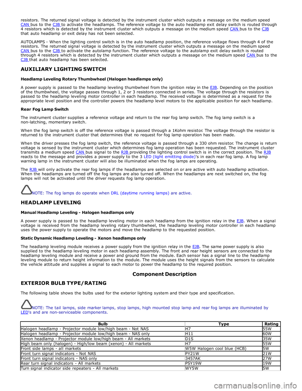
Bulb Type Rating Halogen headlamp - Projector module low/high beam - Not NAS H7 55W Halogen headlamp - Projector module low/high beam - NAS only H11 60W Xenon headlamp - Projector module low/high beam - All markets D1S 35W High beam only (halogen) - High/low beam (xenon) - All markets H7 55W Front side lamps - all markets W5W Halogen cool blue (HCB) 5W Front turn signal indicators - Not NAS PY21W 21W Front turn signal indicators - NAS only 3457AK 27W Rear turn signal indicators - All markets PSY19W 19W Turn signal indicator side repeaters - All markets WY5W 5W
Page 2033 of 3039
Halogen Low/high Beam Headlamp
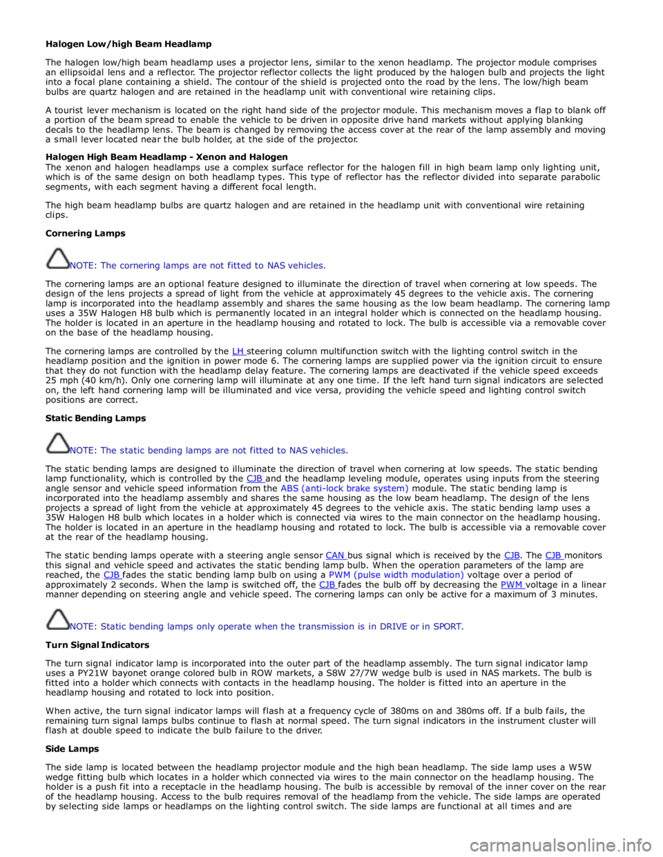
The halogen low/high beam headlamp uses a projector lens, similar to the xenon headlamp. The projector module comprises
an ellipsoidal lens and a reflector. The projector reflector collects the light produced by the halogen bulb and projects the light
into a focal plane containing a shield. The contour of the shield is projected onto the road by the lens. The low/high beam
bulbs are quartz halogen and are retained in the headlamp unit with conventional wire retaining clips.
A tourist lever mechanism is located on the right hand side of the projector module. This mechanism moves a flap to blank off
a portion of the beam spread to enable the vehicle to be driven in opposite drive hand markets without applying blanking
decals to the headlamp lens. The beam is changed by removing the access cover at the rear of the lamp assembly and moving
a small lever located near the bulb holder, at the side of the projector.
Halogen High Beam Headlamp - Xenon and Halogen
The xenon and halogen headlamps use a complex surface reflector for the halogen fill in high beam lamp only lighting unit,
which is of the same design on both headlamp types. This type of reflector has the reflector divided into separate parabolic
segments, with each segment having a different focal length.
The high beam headlamp bulbs are quartz halogen and are retained in the headlamp unit with conventional wire retaining
clips.
Cornering Lamps
NOTE: The cornering lamps are not fitted to NAS vehicles.
The cornering lamps are an optional feature designed to illuminate the direction of travel when cornering at low speeds. The
design of the lens projects a spread of light from the vehicle at approximately 45 degrees to the vehicle axis. The cornering
lamp is incorporated into the headlamp assembly and shares the same housing as the low beam headlamp. The cornering lamp
uses a 35W Halogen H8 bulb which is permanently located in an integral holder which is connected on the headlamp housing.
The holder is located in an aperture in the headlamp housing and rotated to lock. The bulb is accessible via a removable cover
on the base of the headlamp housing.
The cornering lamps are controlled by the LH steering column multifunction switch with the lighting control switch in the headlamp position and the ignition in power mode 6. The cornering lamps are supplied power via the ignition circuit to ensure
that they do not function with the headlamp delay feature. The cornering lamps are deactivated if the vehicle speed exceeds
25 mph (40 km/h). Only one cornering lamp will illuminate at any one time. If the left hand turn signal indicators are selected
on, the left hand cornering lamp will be illuminated and vice versa, providing the vehicle speed and lighting control switch
positions are correct.
Static Bending Lamps
NOTE: The static bending lamps are not fitted to NAS vehicles.
The static bending lamps are designed to illuminate the direction of travel when cornering at low speeds. The static bending
lamp functionality, which is controlled by the CJB and the headlamp leveling module, operates using inputs from the steering angle sensor and vehicle speed information from the ABS (anti-lock brake system) module. The static bending lamp is
incorporated into the headlamp assembly and shares the same housing as the low beam headlamp. The design of the lens
projects a spread of light from the vehicle at approximately 45 degrees to the vehicle axis. The static bending lamp uses a
35W Halogen H8 bulb which locates in a holder which is connected via wires to the main connector on the headlamp housing.
The holder is located in an aperture in the headlamp housing and rotated to lock. The bulb is accessible via a removable cover
at the rear of the headlamp housing.
The static bending lamps operate with a steering angle sensor CAN bus signal which is received by the CJB. The CJB monitors this signal and vehicle speed and activates the static bending lamp bulb. When the operation parameters of the lamp are
reached, the CJB fades the static bending lamp bulb on using a PWM (pulse width modulation) voltage over a period of approximately 2 seconds. When the lamp is switched off, the CJB fades the bulb off by decreasing the PWM voltage in a linear manner depending on steering angle and vehicle speed. The cornering lamps can only be active for a maximum of 3 minutes.
NOTE: Static bending lamps only operate when the transmission is in DRIVE or in SPORT.
Turn Signal Indicators
The turn signal indicator lamp is incorporated into the outer part of the headlamp assembly. The turn signal indicator lamp
uses a PY21W bayonet orange colored bulb in ROW markets, a S8W 27/7W wedge bulb is used in NAS markets. The bulb is
fitted into a holder which connects with contacts in the headlamp housing. The holder is fitted into an aperture in the
headlamp housing and rotated to lock into position.
When active, the turn signal indicator lamps will flash at a frequency cycle of 380ms on and 380ms off. If a bulb fails, the
remaining turn signal lamps bulbs continue to flash at normal speed. The turn signal indicators in the instrument cluster will
flash at double speed to indicate the bulb failure to the driver.
Side Lamps
The side lamp is located between the headlamp projector module and the high bean headlamp. The side lamp uses a W5W
wedge fitting bulb which locates in a holder which connected via wires to the main connector on the headlamp housing. The
holder is a push fit into a receptacle in the headlamp housing. The bulb is accessible by removal of the inner cover on the rear
of the headlamp housing. Access to the bulb requires removal of the headlamp from the vehicle. The side lamps are operated
by selecting side lamps or headlamps on the lighting control switch. The side lamps are functional at all times and are
Page 2034 of 3039
dependant on a particular ignition mode status. The side lamps will also be illuminated when the lighting control switch is in
the AUTO position and a 'lights on' signal is received by the CJB from the rain/light sensor Side Marker Lamps (NAS only)
The side marker lamp is located in the outer part of the headlamp assembly. The side marker lamp uses a W5W wedge fitting
bulb. The bulb is fitted into a holder which connects with contacts in the headlamp housing. The holder is fitted into an
aperture which connects with contacts in the headlamp housing. The side marker lamp is active at all times when the side
lamps are active.
AUTOMATIC HEADLAMP OPERATION
The automatic headlamp function is a driver assistance system. The driver can override the system operation by selection of
side lamp or headlamp on if the ambient light conditions require front and rear lighting to be active. The automatic headlamp
system uses a light sensor and the CJB, which are connected via a LIN (local interconnect network) bus to control the headlamp functionality. The light sensor is incorporated in the rain/light sensor located on the inside of the windshield, below
the rear view mirror. The wiper system also uses the rain/light sensor for automatic wiper operation.
The light sensor measures the ambient light around the vehicle in a vertical direction and also the angular light level from the
front of the vehicle. The rain/light sensor uses vehicle speed signals, wiper switch position and the park position of the front
wipers to control the system. The automatic headlamp operation uses ambient light levels which are monitored by photodiode
incorporated in the rain/light sensor. The rain/light sensor sends a lights on/off request to the CJB on the LIN bus, which responds by switching on the low beam headlamps, front side lamps and rear tail lamps. The automatic headlamps are
activated under the following conditions:
Twilight
Darkness
Rain
Snow
Tunnels
Underground or multistoried car parks.
Operation of the automatic headlamps requires the ignition to be in ignition mode 6, the lighting control switch to be in the
'AUTO' position and a lights on request signal from the light sensor. If the rain sensor signal activates the fast speed wipers,
the low beam headlamps are activated, providing the lighting control switch is in the 'AUTO' position.
HEADLAMP LEVELING
Headlamp leveling provides for the adjustment of the vertical aim of the headlamps. The leveling system is primarily required
to minimise glare to other road users when a heavy load is in the rear of the vehicle. Two systems of headlamp leveling are
available; manual and static dynamic.
Manual Headlamp Leveling
The manual system uses a thumbwheel rheostat to adjust the vertical alignment of the headlamps to compensate for differing
vehicle loading. The rotary thumbwheel is located on the auxiliary lighting switch, adjacent to the illumination dimmer
thumbwheel. Three positions are available to adjust the headlamps to a position to prevent glare to other road users.
Static Dynamic Headlamp Leveling
The static dynamic headlamp leveling system uses the following components:
Front and rear vehicle height sensors
Two headlamp leveling, vertical adjustment motors
Headlamp leveling module
Ignition in mode 6
Vehicle speed information from ABS module.
The static dynamic system uses height sensors fitted to the front and rear suspension and a headlamp leveling module which
periodically monitors the vehicle attitude and adjusts the headlamp vertical alignment accordingly.
Static dynamic headlamp leveling is controlled by a headlamp leveling module located in the lower instrument panel, behind
the glovebox.
The height sensors are both located on the RH side of the vehicle. The front sensor is attached to the front suspension lower arm with a strap and to the front sub frame with a bracket and 2 bolts. The rear sensor is attached to the rear suspension
upper control arm with a cable tied clip and to the rear sub frame with a bracket and 2 bolts. Each sensor has 3 connections to
the headlamp leveling module; power, ground and signal.
DAYTIME RUNNING LAMPS (DRL)
Refer to DRL section for details. Refer to: Daytime Running Lamps (DRL) (417-04 Daytime Running Lamps (DRL), Description and Operation).
REAR LAMP ASSEMBLY
The rear lamp assembly is a 2 piece unit, with one part located in the rear quarter panel and the second part attached to the
luggage compartment lid. The outer rear lamp assembly is located in a recess in the vehicle body. The lamp is secured with 2
studs inboard studs on the lamp body which are secured to the vehicle body with 2 nuts. A third outboard stud and nut secures
Page 2035 of 3039
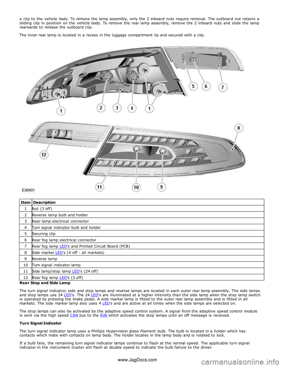
1 Nut (3 off) 2 Reverse lamp bulb and holder 3 Rear lamp electrical connector 4 Turn signal indicator bulb and holder 5 Securing clip 6 Rear fog lamp electrical connector 7 Rear fog lamp LED's and Printed Circuit Board (PCB) 8 Side marker LED's (4 off - all markets) 9 Reverse lamp 10 Turn signal indicator lamp 11 Side lamp/stop lamp LED's (24 off) 12 Rear fog lamp LED's (3 off) Rear Stop and Side Lamp
The turn signal indicator, side and stop lamps and reverse lamps are located in each outer rear lamp assembly. The side lamps
and stop lamps use 24 LED's. The 24 LED's are illuminated at a higher intensity than the side lamp when the stop lamp switch is operated by pressing the brake pedal. A side marker lamp is fitted to the outer rear lamp assembly and is fitted in all
markets. The side marker lamp also uses 4 LED's and are active at all times when the side lamps are selected on.
The stop lamps can also be activated by the adaptive speed control system. A signal from the adaptive speed control module
is sent via the high speed CAN bus to the RJB which activates the stop lamps until an off message is received. Turn Signal Indicator
The turn signal indicator lamp uses a Phillips Hypervision glass filament bulb. The bulb is located in a holder which has
contacts which mate with contacts on lamp body. The holder locates in the lamp body and is rotated to lock.
If a bulb fails, the remaining turn signal indicator lamps continue to flash at the normal speed. The applicable turn signal
indicator in the instrument cluster will flash at double speed to indicate the bulb failure to the driver. www.JagDocs.com
Page 2055 of 3039
Interior Lighting - Interior Lighting - Overview
Description and Operation
OVERVIEW Published: 11-May-2011
Interior lighting is provided to enable the safe entry and departure from the vehicle for the driver and passengers in low
ambient light conditions, without any manual switching of the lights.
NOTE: The term interior lamps also includes the door mirror approach lamps.
The interior lamps are controlled by the CJB (central junction box) and the RJB (rear junction box) and have 2 modes of
operation: manual and automatic. The front interior lamps in the front overhead console are operated using the 'JaguarSense'
system. The system uses capacitive proximity sensor technology for the switch operation which is integral with the overhead
console. The rear overhead console interior lamps have conventional switches.
In the manual mode the interior lamps can be switched on and off with the JaguarSense system. Positioning your hand
adjacent to each lamp in the front overhead console will switch interior lamps on or off and completely disable the interior
lamp system. In the automatic mode the interior lamp functionality is controlled by the CJB and the RJB and reacts to the vehicle being locked or unlocked and opening the vehicle doors.
In manual mode the interior lamps can be operated by placing your finger(s) close to, or touch, the surface of the appropriate
lamp. The courtesy light and map reading lamps can be operated manually by the 'JaguarSense' system. When in automatic
mode, the courtesy lamp functionality is also controlled by the CJB and the RJB and reacts to the vehicle being locked or unlocked and opening the vehicle doors. To deactivate or activate automatic illumination, touch the front courtesy lamp for
approximately 2 seconds
The driver's and passenger door approach lamps are controlled by the driver's door module and the passenger door module
respectively and operate with the automatic mode. The door modules receive a power supply from the RJB and receive information to illuminate the approach lamps on the medium speed CAN (controller area network) bus from the RJB and the CJB. www.JagDocs.com
Page 2056 of 3039

A = Hardwired; N = Medium speed CAN Bus 1 Battery 2 BJB (battery junction box) - Megafuse 3 BJB - Megafuse 4 RJB (rear junction box) 5 Driver's door mirror approach lamp 6 Driver's door module
Page 2067 of 3039

Published: 11-May-2011
Module Communications Network - Communications Network - Overview
Description and Operation
OVERVIEW
A number of different types of communication network are incorporated into the vehicle wiring harnesses for the transmission
of commands and information between control modules. The configuration installed on a particular vehicle depends on the
model and equipment level.
NOTE: The control diagrams shown later in this section are schematics reflecting communications networks fitted to LH
(left-hand) vehicles only. For detailed layouts of the various communications networks fitted to LHD (left-hand drive) and RHD
(right-hand drive) vehicles, refer to the Electrical Guide.
The communications networks available on the vehicle are shown in the table below.
Network Baud Rate LIN (local interconnect network) bus 9.6 kbits/s Medium speed CAN (controller area network) bus 125 kbits/s High speed CAN bus 500 kbits/s Media Orientated System Transport (MOST) ring 24 mbits/s
Page 2071 of 3039

N = Medium speed CAN (controller area network) bus 1 Parking aid module 2 RJB 3 Keyless vehicle module 4 RH blind spot monitoring module 5 Driver's seat module 6 Front seat climate control module 7 Information control module 8 ATC module 9 CJB 10 Diagnostic socket 11 Instrument cluster 12 Integrated control panel 13 Front passenger door control module
Page 2072 of 3039
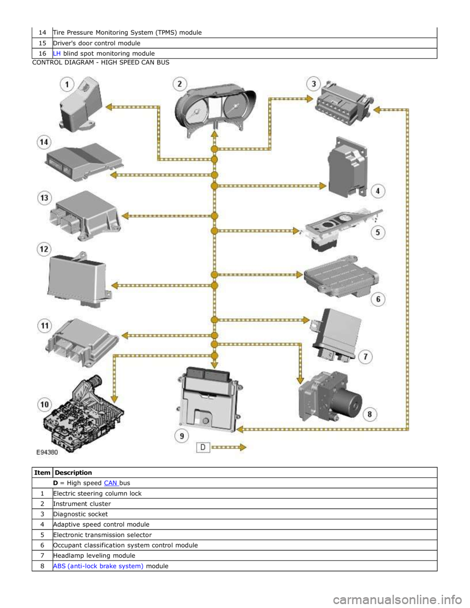
Tire Pressure Monitoring System (TPMS) module 15 Driver's door control module 16 LH blind spot monitoring module CONTROL DIAGRAM - HIGH SPEED CAN BUS
Item Description D = High speed CAN bus 1 Electric steering column lock 2 Instrument cluster 3 Diagnostic socket 4 Adaptive speed control module 5 Electronic transmission selector 6 Occupant classification system control module 7 Headlamp leveling module 8 ABS (anti-lock brake system) module
Page 2076 of 3039

CAN Harness Architecture
For a detailed description of the CAN Networks and architecture, refer to the relevant Description and Operation section in the
Workshop Manual.
CAN Network Integrity Tests
If a control module is suspected of non-communication, the Network Integrity test application available on the manufacturer
approved diagnostic system can be used to confirm if communication is possible between the control modules on the vehicle
and the manufacturer approved diagnostic system (via the J1962 diagnostic connector ). The results from the test can be used
to determine if either a single module or multiple modules are failing to communicate.
CAN Terminating Modules
If the Network Integrity test indicates that one or more module on one of the CAN networks (HS or MS) are failing to
communicate, there are several checks that can be made. The first step is to identify if both of the CAN terminating modules
on each individual CAN Bus are communicating. If both CAN terminating modules for each individual CAN Bus are
communicating (identified via the Network Integrity test), then it can be confirmed that the main 'backbone' of the CAN
harness is complete. The main 'backbone' of the CAN harness consists of all the modules connected to the CAN harness via a
'loop' configuration and also includes the two terminating modules.
Communication with both CAN terminating modules via the Network Integrity test confirms the physical integrity of the main
'backbone' of the CAN harness (and the harness spur to the J1962 diagnostic connector). This means that there is no
requirement to check the resistance of the CAN Network. This is because the standard check for 60 ohms across the CAN High
and CAN Low lines will not provide any additional information regarding the physical condition of the CAN harness, beyond
what has already been determined from the Network Integrity test.
Non-Communication of a Terminating Module
If a Network Integrity test reveals a terminating module is failing to communicate it can indicate a break in the main
'backbone' of the CAN harness. The first checks should always be to confirm the power and ground supplies to the
non-communicating module are correct. Providing these are correct, the resistance between the CAN High and CAN Low lines at
the J1962 connector can be checked to determine the integrity of the main 'backbone' of the CAN harness. After disconnecting
the battery a reading of 120 ohms would indicate an open circuit in the main 'backbone' of the CAN harness. Alternatively, a
reading of 60 ohms would indicate that there is no open circuit fault with the main 'backbone' of the CAN harness.
It is worth noting that even if one of the terminating modules is disconnected from the CAN harness, communications between
the modules still connected may still be possible. Therefore communication between the manufacturer approved diagnostic
system and the connected modules may also be possible.
Locating CAN Harness Open Circuits
In the case where multiple modules, including a terminating module, are failing to communicate, having first confirmed the
power and ground supplies are correct, the approximate location of the open circuit can be identified from analysis of the
Network Integrity test results and reference to the relevant CAN network circuit diagrams. For example, if an open circuit
existed in a certain position on the CAN harness, any module positioned on the Network between the J1962 connector and the
open circuit should return a response during the Network Integrity test. No responses would be returned from any modules
past the open circuit fault in the Network.
CAN Harness 'Spur' Type Configuration Circuits
If, after the initial checks (Network Integrity test using the manufacturer approved diagnostic system, and power and ground
supplies to the module have been checked and confirmed as correct), a module that is connected to the CAN harness via a
'spur' type configuration is suspected of not communicating, then the physical integrity of the CAN harness 'spur' can be
checked.
This is most easily undertaken by individually checking the continuity of the CAN High and CAN Low lines between the
non-communicating module connector (with the module disconnected) and the J1962 diagnostic connector.
'Lost Communications' DTCs
As well as the methods described so far in this document, which can be used to determine the location of an open circuit in
the CAN harness, 'Lost Communications' DTCs can also be used for this purpose. Lost communication DTCs mean that a
module is not receiving CAN information from another module.
For example, if a global DTC read were to be carried out, only DTCs stored in the modules that the manufacturer approved
diagnostic system could communicate with would be displayed. If there was an open circuit fault in a certain position on the
CAN harness, the modules that could display DTCs would all be prior to the open circuit on the Network, and these modules
should display 'Lost Communications' DTCs with all the modules located on the Network past the open circuit fault.
'Bus off' DTCs
The references to bus and its condition refer to the network concerned and the modules on that network.
If a module logs a 'Bus Off' DTC, it means that the module has detected CAN transmission errors and has disabled it's own
CAN transmissions and disconnected itself from the network in an attempt to allow the rest of the network to function. At this
point the 'Bus Off' DTC is set. A common cause of 'Bus Off' DTCs can be a short circuit in the CAN network.