display JAGUAR XFR 2010 1.G Workshop Manual
[x] Cancel search | Manufacturer: JAGUAR, Model Year: 2010, Model line: XFR, Model: JAGUAR XFR 2010 1.GPages: 3039, PDF Size: 58.49 MB
Page 2153 of 3039
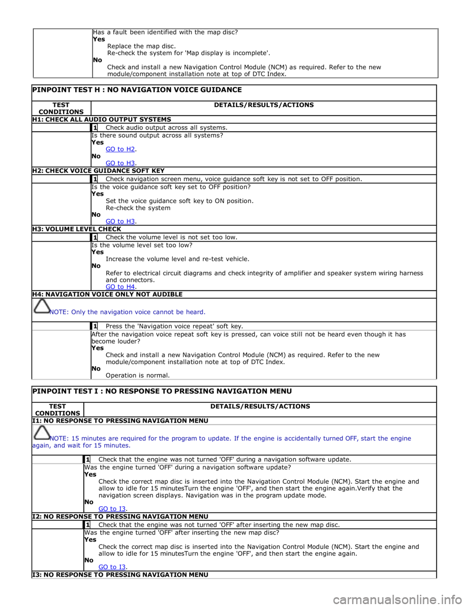
PINPOINT TEST H : NO NAVIGATION VOICE GUIDANCE TEST
CONDITIONS DETAILS/RESULTS/ACTIONS H1: CHECK ALL AUDIO OUTPUT SYSTEMS 1 Check audio output across all systems. Is there sound output across all systems? Yes
GO to H2. No
GO to H3. H2: CHECK VOICE GUIDANCE SOFT KEY 1 Check navigation screen menu, voice guidance soft key is not set to OFF position. Is the voice guidance soft key set to OFF position? Yes
Set the voice guidance soft key to ON position.
Re-check the system
No
GO to H3. H3: VOLUME LEVEL CHECK 1 Check the volume level is not set too low. Is the volume level set too low? Yes
Increase the volume level and re-test vehicle.
No
Refer to electrical circuit diagrams and check integrity of amplifier and speaker system wiring harness
and connectors.
GO to H4. H4: NAVIGATION VOICE ONLY NOT AUDIBLE
NOTE: Only the navigation voice cannot be heard. 1 Press the 'Navigation voice repeat' soft key. After the navigation voice repeat soft key is pressed, can voice still not be heard even though it has
become louder? Yes
Check and install a new Navigation Control Module (NCM) as required. Refer to the new
module/component installation note at top of DTC Index.
No
Operation is normal.
PINPOINT TEST I : NO RESPONSE TO PRESSING NAVIGATION MENU TEST
CONDITIONS DETAILS/RESULTS/ACTIONS I1: NO RESPONSE TO PRESSING NAVIGATION MENU
NOTE: 15 minutes are required for the program to update. If the engine is accidentally turned OFF, start the engine
again, and wait for 15 minutes. 1 Check that the engine was not turned 'OFF' during a navigation software update. Was the engine turned 'OFF' during a navigation software update? Yes
Check the correct map disc is inserted into the Navigation Control Module (NCM). Start the engine and
allow to idle for 15 minutesTurn the engine 'OFF', and then start the engine again.Verify that the
navigation screen displays. Navigation was in the program update mode.
No
GO to I3. I2: NO RESPONSE TO PRESSING NAVIGATION MENU 1 Check that the engine was not turned 'OFF' after inserting the new map disc. Was the engine turned 'OFF' after inserting the new map disc? Yes
Check the correct map disc is inserted into the Navigation Control Module (NCM). Start the engine and
allow to idle for 15 minutesTurn the engine 'OFF', and then start the engine again.
No
GO to I3. I3: NO RESPONSE TO PRESSING NAVIGATION MENU Has a fault been identified with the map disc?
Yes
Replace the map disc.
Re-check the system for 'Map display is incomplete'.
No
Check and install a new Navigation Control Module (NCM) as required. Refer to the new
module/component installation note at top of DTC Index.
Page 2154 of 3039
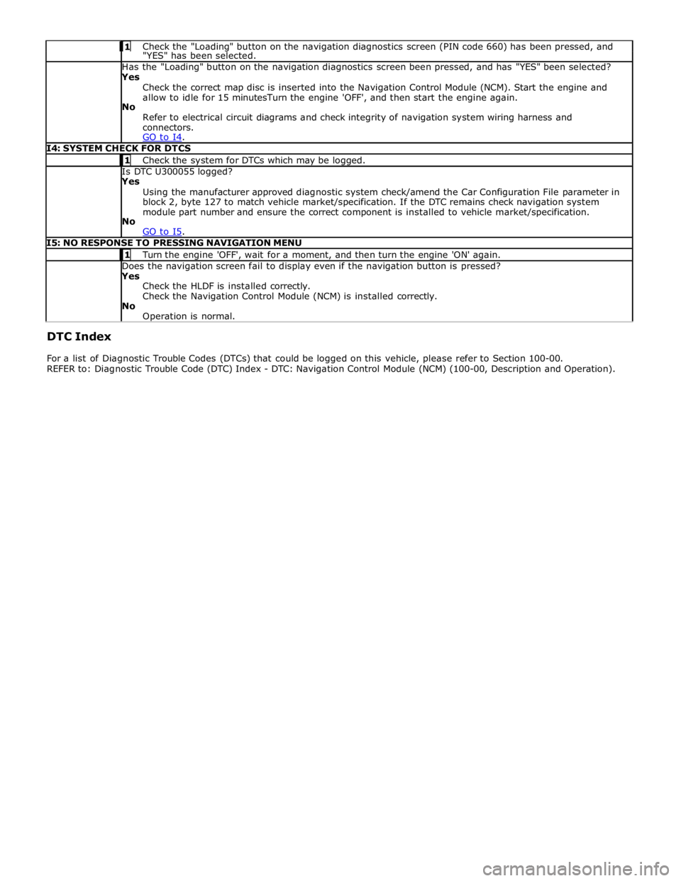
Check the "Loading" button on the navigation diagnostics screen (PIN code 660) has been pressed, and "YES" has been selected. Has the "Loading" button on the navigation diagnostics screen been pressed, and has "YES" been selected? Yes
Check the correct map disc is inserted into the Navigation Control Module (NCM). Start the engine and
allow to idle for 15 minutesTurn the engine 'OFF', and then start the engine again.
No
Refer to electrical circuit diagrams and check integrity of navigation system wiring harness and
connectors.
GO to I4. I4: SYSTEM CHECK FOR DTCS 1 Check the system for DTCs which may be logged. Is DTC U300055 logged? Yes
Using the manufacturer approved diagnostic system check/amend the Car Configuration File parameter in
block 2, byte 127 to match vehicle market/specification. If the DTC remains check navigation system
module part number and ensure the correct component is installed to vehicle market/specification.
No
GO to I5. I5: NO RESPONSE TO PRESSING NAVIGATION MENU 1 Turn the engine 'OFF', wait for a moment, and then turn the engine 'ON' again. Does the navigation screen fail to display even if the navigation button is pressed? Yes
Check the HLDF is installed correctly.
Check the Navigation Control Module (NCM) is installed correctly.
No
Operation is normal. DTC Index
For a list of Diagnostic Trouble Codes (DTCs) that could be logged on this vehicle, please refer to Section 100-00.
REFER to: Diagnostic Trouble Code (DTC) Index - DTC: Navigation Control Module (NCM) (100-00, Description and Operation).
Page 2167 of 3039

10 Diagnostic socket 11 Pedestrian protection control module 12 Electric steering column lock 13 TCM 14 ABS (anti-lock brake system) module COMPONENT LOCATION - MOST
Item Description NOTE: LHD vehicle shown 1 Touch Screen Display (TSD) 2 Integrated audio module 3 Entertainment system control module 4 Digital Audio Broadcast (DAB)/Satellite Digital Audio Radio System (SDARS) 5 Multimedia module
Page 2172 of 3039
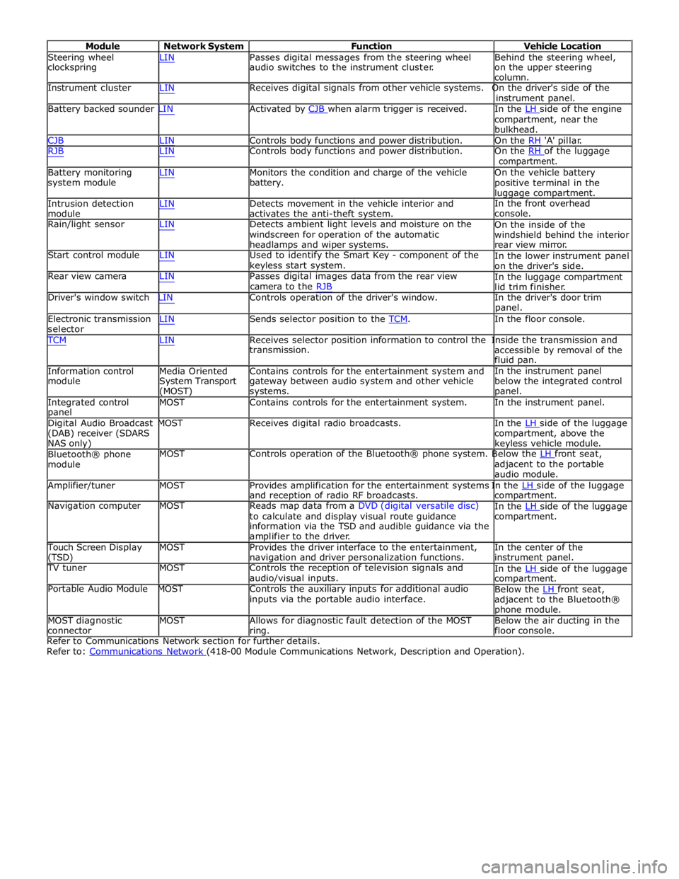
Module Network System Function Vehicle Location
Steering wheel
clockspring LIN Passes digital messages from the steering wheel
audio switches to the instrument cluster. Behind the steering wheel,
on the upper steering
column.
Instrument cluster LIN Receives digital signals from other vehicle systems. On the driver's side of the
instrument panel.
Battery backed sounder LIN Activated by CJB when alarm trigger is received. In the LH side of the engine compartment, near the
bulkhead.
CJB LIN Controls body functions and power distribution. On the RH 'A' pillar.
RJB LIN Controls body functions and power distribution. On the RH of the luggage compartment.
Battery monitoring
system module
Intrusion detection
module LIN Monitors the condition and charge of the vehicle
battery.
LIN Detects movement in the vehicle interior and
activates the anti-theft system. On the vehicle battery
positive terminal in the
luggage compartment.
In the front overhead
console.
Rain/light sensor LIN Detects ambient light levels and moisture on the
windscreen for operation of the automatic
headlamps and wiper systems.
Start control module LIN Used to identify the Smart Key - component of the
keyless start system.
Rear view camera LIN Passes digital images data from the rear view
camera to the RJB On the inside of the
windshield behind the interior
rear view mirror.
In the lower instrument panel
on the driver's side.
In the luggage compartment
lid trim finisher.
Driver's window switch LIN Controls operation of the driver's window. In the driver's door trim
panel.
Electronic transmission
selector LIN Sends selector position to the TCM. In the floor console. TCM LIN Receives selector position information to control the Inside the transmission and
Information control
module
Media Oriented
System Transport
(MOST) transmission.
Contains controls for the entertainment system and
gateway between audio system and other vehicle
systems. accessible by removal of the
fluid pan.
In the instrument panel
below the integrated control
panel.
Integrated control
panel MOST Contains controls for the entertainment system. In the instrument panel.
Digital Audio Broadcast MOST Receives digital radio broadcasts. In the LH side of the luggage (DAB) receiver (SDARS
NAS only)
Bluetooth® phone
module compartment, above the
keyless vehicle module.
MOST Controls operation of the Bluetooth® phone system. Below the LH front seat, adjacent to the portable
audio module.
Amplifier/tuner MOST Provides amplification for the entertainment systems In the LH side of the luggage and reception of radio RF broadcasts.
Navigation computer MOST Reads map data from a DVD (digital versatile disc)
to calculate and display visual route guidance
information via the TSD and audible guidance via the
amplifier to the driver. compartment.
In the LH side of the luggage compartment.
Touch Screen Display
(TSD) MOST Provides the driver interface to the entertainment,
navigation and driver personalization functions. In the center of the
instrument panel.
TV tuner MOST Controls the reception of television signals and
audio/visual inputs.
Portable Audio Module MOST Controls the auxiliary inputs for additional audio
inputs via the portable audio interface. In the LH side of the luggage compartment.
Below the LH front seat, adjacent to the Bluetooth®
phone module.
MOST diagnostic
connector MOST Allows for diagnostic fault detection of the MOST
ring. Below the air ducting in the
floor console.
Refer to Communications Network section for further details.
Refer to: Communications Network (418-00 Module Communications Network, Description and Operation).
Page 2294 of 3039
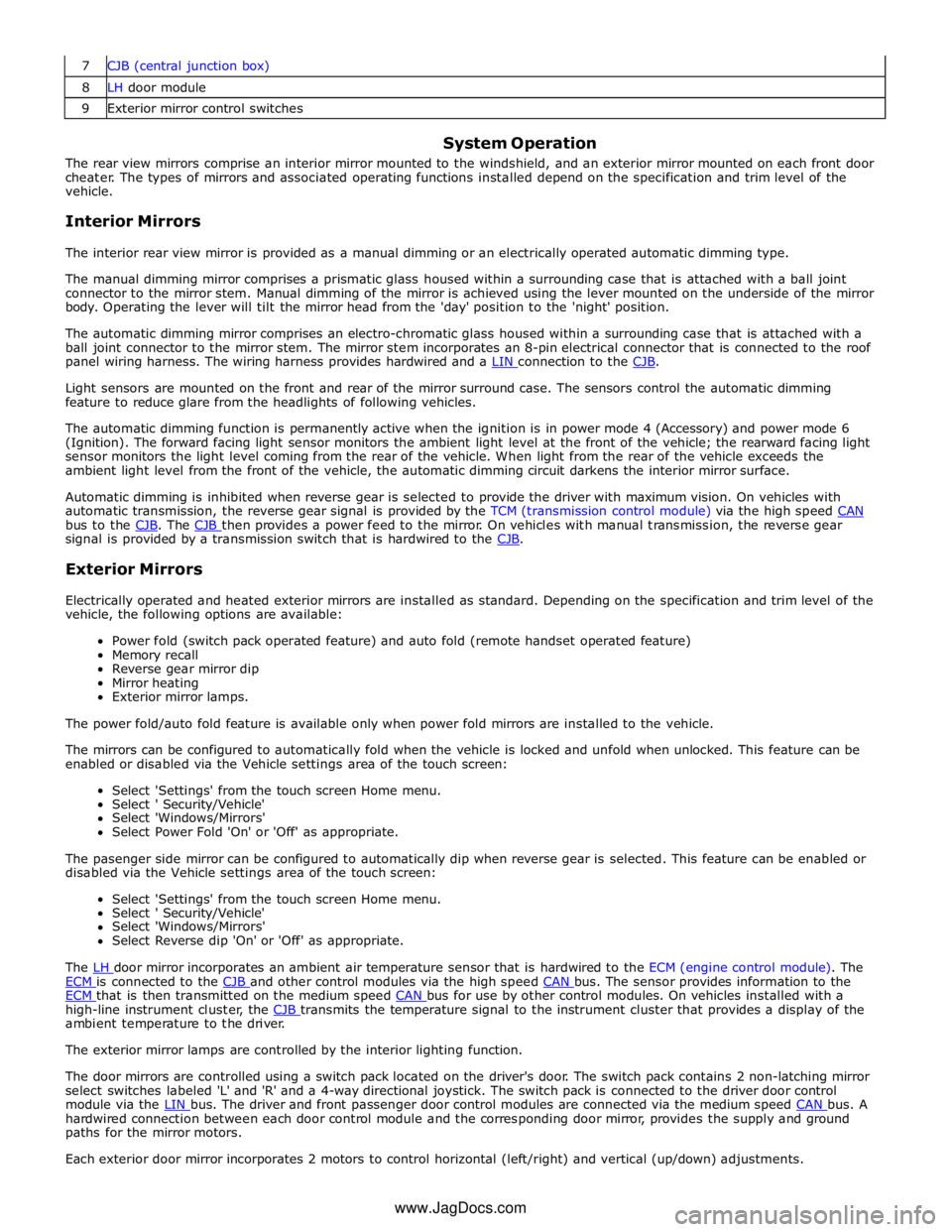
8 LH door module 9 Exterior mirror control switches
System Operation
The rear view mirrors comprise an interior mirror mounted to the windshield, and an exterior mirror mounted on each front door
cheater. The types of mirrors and associated operating functions installed depend on the specification and trim level of the
vehicle.
Interior Mirrors
The interior rear view mirror is provided as a manual dimming or an electrically operated automatic dimming type.
The manual dimming mirror comprises a prismatic glass housed within a surrounding case that is attached with a ball joint
connector to the mirror stem. Manual dimming of the mirror is achieved using the lever mounted on the underside of the mirror
body. Operating the lever will tilt the mirror head from the 'day' position to the 'night' position.
The automatic dimming mirror comprises an electro-chromatic glass housed within a surrounding case that is attached with a
ball joint connector to the mirror stem. The mirror stem incorporates an 8-pin electrical connector that is connected to the roof
panel wiring harness. The wiring harness provides hardwired and a LIN connection to the CJB.
Light sensors are mounted on the front and rear of the mirror surround case. The sensors control the automatic dimming
feature to reduce glare from the headlights of following vehicles.
The automatic dimming function is permanently active when the ignition is in power mode 4 (Accessory) and power mode 6
(Ignition). The forward facing light sensor monitors the ambient light level at the front of the vehicle; the rearward facing light
sensor monitors the light level coming from the rear of the vehicle. When light from the rear of the vehicle exceeds the
ambient light level from the front of the vehicle, the automatic dimming circuit darkens the interior mirror surface.
Automatic dimming is inhibited when reverse gear is selected to provide the driver with maximum vision. On vehicles with
automatic transmission, the reverse gear signal is provided by the TCM (transmission control module) via the high speed CAN bus to the CJB. The CJB then provides a power feed to the mirror. On vehicles with manual transmission, the reverse gear signal is provided by a transmission switch that is hardwired to the CJB.
Exterior Mirrors
Electrically operated and heated exterior mirrors are installed as standard. Depending on the specification and trim level of the
vehicle, the following options are available:
Power fold (switch pack operated feature) and auto fold (remote handset operated feature)
Memory recall
Reverse gear mirror dip
Mirror heating
Exterior mirror lamps.
The power fold/auto fold feature is available only when power fold mirrors are installed to the vehicle.
The mirrors can be configured to automatically fold when the vehicle is locked and unfold when unlocked. This feature can be
enabled or disabled via the Vehicle settings area of the touch screen:
Select 'Settings' from the touch screen Home menu.
Select ' Security/Vehicle'
Select 'Windows/Mirrors'
Select Power Fold 'On' or 'Off' as appropriate.
The pasenger side mirror can be configured to automatically dip when reverse gear is selected. This feature can be enabled or
disabled via the Vehicle settings area of the touch screen:
Select 'Settings' from the touch screen Home menu.
Select ' Security/Vehicle'
Select 'Windows/Mirrors'
Select Reverse dip 'On' or 'Off' as appropriate.
The LH door mirror incorporates an ambient air temperature sensor that is hardwired to the ECM (engine control module). The ECM is connected to the CJB and other control modules via the high speed CAN bus. The sensor provides information to the ECM that is then transmitted on the medium speed CAN bus for use by other control modules. On vehicles installed with a high-line instrument cluster, the CJB transmits the temperature signal to the instrument cluster that provides a display of the ambient temperature to the driver.
The exterior mirror lamps are controlled by the interior lighting function.
The door mirrors are controlled using a switch pack located on the driver's door. The switch pack contains 2 non-latching mirror
select switches labeled 'L' and 'R' and a 4-way directional joystick. The switch pack is connected to the driver door control
module via the LIN bus. The driver and front passenger door control modules are connected via the medium speed CAN bus. A hardwired connection between each door control module and the corresponding door mirror, provides the supply and ground
paths for the mirror motors.
Each exterior door mirror incorporates 2 motors to control horizontal (left/right) and vertical (up/down) adjustments. www.JagDocs.com
Page 2314 of 3039

Note:
A =
Hardwired;
N
=
Medium
speed
CAN
(controller
area
network) bus;
P
=
MOST
ring
1
Battery
2
BJB
3
ATC
(automatic
temperature
control) module
4
RJB
(rear
junction
box)
5
Touch Screen
Display
(TSD)
6
Information
and
Entertainment
module
www.JagDocs.com
Page 2317 of 3039
memory positions to be stored and 'set' button with integral LED (light emitting diode). The seat, door mirror and steering
column motors have position sensors which provide feedback to driver's seat module.
Once the driver's seat, steering column and exterior mirrors have been adjusted, the vehicle is able to memorize these
settings for future use by using the following procedure:
Push the memory 'SET' button, the LED in the switch will illuminate Press the memory button 1 or 2 to memorize the current settings. The LED will extinguish, and a chime will sound to confirm that the settings have been memorized. If the ignition is on, power mode 6, the message center will display a
confirmation message.
The positions can be recalled by pressing the applicable button 1 or 2.
Stall Detection
Seat, steering column and mirror motors are deemed to have stalled if there is no change in the inputs that are received from
the corresponding feedback sensors for 200 ms (seat).
If a stall condition is detected then the drive to that motor is cancelled for the remainder of that memory operation (memory
recall) or until the switch is re-selected (manual movement).
If the motor movement has stopped due to loss of sensor feedback, either stall or sensor failure, then that motor may be
activated again, to move past the stall position, by re-selecting the appropriate switch and pressing for longer than 2 seconds.
This allows control of the motor to be maintained if sensor feedback is lost.
Upon re-selection of movement, if sensor pulses are detected then the motor will continue to be driven until the switch is
released or another stall condition is detected. If sensor feedback is not detected then the motor is only driven for 0.5 second
and then stops until the switch is released and then pressed again, when a further 0.5 second of activation is permitted, and
so on, this is known as inch mode.
For all seat motor manual movements, whenever a motor is driven and a stall occurs, the memory control module records the
position at which the stall occurred. If movement occurs beyond a stall position, then that position is erased from the control
modules memory. This will always allow movement past a previously recorded stall position once movement has been
registered beyond that position. This is the case for both manual and memory movement.
Initialization
When a replacement driver's seat module is fitted, it should be calibrated a Jaguar approved diagnostic system so that the
module can learn the seats absolute position.
Battery Monitor
If the battery voltage drops below 10.5 Volts, then the driver's seat module ignores all requests for a memory recall until the
battery voltage has reached 11.5 Volts. This will conserve as much power in the vehicle battery as possible to enable engine
cranking.
REAR SEATS - DESCRIPTION
The rear seat features a single piece cushion and a 60/40 split squab. Two latches are secured to the rear bulkhead by a pair
of M8 bolts to retain the seat squabs in the upright position. The latches can be released to fold down the individual cushions
by pulling a cable release located below the rear window parcel shelf in the luggage compartment.
ISOFIX fastening points are attached to the vehicle floor to provide secure fastening for compatible child seats.
A centrally mounted center arm rest can be folded down from the 60% squab. The arm rest contains two drinks holders.
Page 2451 of 3039

a power supply to operate the glovebox latch to unlock the glovebox.
The glove box opening is inhibited by the CJB if the anti-theft alarm system is armed and if valet mode is selected using the Touch Screen Display (TSD). The CJB detects the voltage signal from the switch but will not operate the glovebox latch if other condition exists.
GLOVEBOX SWITCH DESCRIPTION Component Description
The conventional glove box switch is located behind the instrument panel veneer. The round button of the switch is visible
through an aperture in the veneer.
Two screws hold the switch in position behind the veneer. The veneer panel has two bosses which the screws are threaded
into.
Page 2537 of 3039
7 Windshield washer pump 8 Wiper/Washer switch - RH (right-hand) steering column multifunction switch 9 Instrument cluster 10 CJB (central junction box) 11 BJB (battery junction box)
WINDSHIELD WIPERS System Operation
Operation of the wipers and washers is controlled by the CJB in response to driver inputs from the wiper control switch and signals from the rain/light sensor. The instrument cluster monitors the condition of the wiper/washer control switch and
transmits driver requests to the CJB over the medium speed CAN bus.
The wiper control switch is connected via hardwired connections to the instrument cluster. The instrument cluster outputs on 4
wires a reference voltage to the wash/wipe switch, the auto wiper switch, the wiper switch and the flick wipe switch. All the
switches are connected to the instrument cluster on a common ground. Each switch function is connected to ground via a
resistor or series of resistors and the instrument cluster monitors the ground signal and determines which function has been
selected. The instrument cluster then outputs the appropriate message on the medium speed CAN bus to the CJB which responds to the requested wiper function. The CJB then activates the appropriate function either directly or via relays in the EJB for the wipers and headlamp powerwashers. Speed Dependent Mode
When the wipers are operating, a vehicle speed signal received by the CJB on the high speed CAN bus is used to operate a speed dependent mode. If the wipers are in fast wipe and the vehicle speed decreases to below 2 km/h (1.2 mph), the wipers
will reduce to the normal wipe speed. When the vehicle speed increases to above 8 km/h (5 mph) the fast wiper speed
selection is restored. If slow speed is selected and the vehicle speed drops below 2km/h (1.2 mph), the wipers will operate in
the intermittent mode. When the vehicle speed increases to above 8 km/h (5 mph) the slow wiper speed selection is restored
– this feature is configurable by the dealer using the approved Jaguar diagnostic system.
Wiper Motor
The wiper motor is controlled by the CJB. The CJB is connected to a wiper motor normal/fast relay in the EJB on 2 wires. The CJB is also connected to a wiper run/park relay, also located in the EJB.
Driver requests are received by the CJB which energizes the wiper motor normal/fast relay in the appropriate mode (normal or fast wipe) and also energizes the run/park relay in the run mode by providing a ground for the relay coils. When wiper
operation is deselected by the driver, the CJB monitors a park switch which is integral with the wiper motor. On receipt of a signal from the park switch, the CJB de-energises the run/park relay, removing the power supply through the normal/fast relay, stopping the wipers in the park position on the windshield.
The wiper motor is a DC (direct current) motor which drives a gear wheel via a worm drive attached to the motor spindle. The
motor has 3 sets of brushes with one brush connected to ground. When the normal/fast relay is energized in the normal
position, a power feed is supplied to the brush directly opposite the ground brush and operates the motor at slow speed.
When the relay is energized in the fast position, a power feed is connected to the second motor brush, which is offset from the
ground brush and operates the motor at the fast speed. With power supplied through the offset brush, the current flows
through fewer motor coil windings. This results in a lower resistance to current flow to the ground brush and produces a higher
motor rotational speed.
WINDSHIELD WASHERS
The windshield washers are controlled by the CJB. A driver request for washer operation, via the wiper control switch, is passed to the instrument cluster on the LIN bus. The instrument cluster passes the message to the CJB on the medium speed CAN bus.
The CJB energizes the windshield washer pump during the up stroke of the first 2 wash/wipe cycles. This ensures that wiper fluid is pushed to the sides of the windshield and eliminates the trail of fluid which can occur if the fluid is pushed to the
bottom of the windshield. The wipers will continue for 3 more cycles, followed after a delay of 4 seconds, by a single dry wipe.
NOTE: The dry wipe feature is configurable using an approved Jaguar diagnostic system.
The operation of the washer pump on the wiper up stroke only is configurable using an approved Jaguar diagnostic system.
The washer button can be pressed and held and the wipers will operate continuously for up to 10 seconds. After this period
when the button is released, the wipers will continue for 3 more cycles, followed after a delay, by a single dry wipe. After this
period washing will be inhibited, the wipers will continue for 3 more cycles, followed after a delay, by a single dry wipe.
Reactivating the switch will recommence the wash/wipe cycle.
RESERVOIR LEVEL SWITCH
The level switch is connected directly to the CJB. The switch is operated by a float which closes contacts within the switch when the fluid level falls to below the switch level. When the contacts are closed a ground path is completed from the CJB through the switch. This is sensed by the CJB which issues a message to the instrument cluster which displays a low fluid level warning.
Page 2653 of 3039

Supplemental Restraint System - Passenger Air Bag Module
Removal and Installation Published: 11-May-2011
Removal
NOTE: Removal steps in this procedure may contain installation details.
1. Refer to: Battery Disconnect and Connect (414-01 Battery, Mounting and Cables, General Procedures).
2. Refer to: Steering Wheel (211-04 Steering Column, Removal and Installation).
3. Refer to: Driver Side Register (412-01 Climate Control, Removal and Installation).
4. Refer to: Information and Entertainment Display (415-01A Information and Entertainment System, Removal and Installation).
5. Refer to: Instrument Panel Speaker (415-01A Information and Entertainment System, Removal and Installation).
6. Refer to: A-Pillar Trim Panel (501-05 Interior Trim and Ornamentation, Removal and Installation).
7. Refer to: Audio and Climate Control Assembly (415-01A Information and Entertainment System, Removal and Installation). 211-326
Locking Tool, Clockspring Special Tool(s)