ECO mode JAGUAR XFR 2010 1.G User Guide
[x] Cancel search | Manufacturer: JAGUAR, Model Year: 2010, Model line: XFR, Model: JAGUAR XFR 2010 1.GPages: 3039, PDF Size: 58.49 MB
Page 395 of 3039

the aluminum wheel knuckle via an integral ball-joint.
Lower Control Arm
The aluminum lower arm locates to the subframe via one cross-axis joint and one plain rubber bush, and to the wheel knuckle
via a second plain rubber bush.
The rear of the control arm has mounting points for the damper and the stabilizer link.
Toe-Link
The toe-link is located between the wheel knuckle and brackets on the subframe.
The toe-link comprises an inner rod with integral axial ball joint. The inner ball joint has a threaded spigot which locates in a
bracket on the subframe and is secured with a locknut. The rod has an internal thread which accepts the outer rod.
The outer rod has a cross-axis joint at its outer end which is located in a clevis on the wheel knuckle, and is secured with a
bolt and locknut.
The length of the toe-link can be adjusted by rotating the inner rod. This allows for adjustment of the toe angle for the rear
wheel. Once set the inner rod can be locked in position by tightening a locknut on the outer rod against the inner rod.
Wheel Knuckle
The cast aluminum wheel knuckle attaches to:
the upper control arm via a ball-joint located in the arm,
the lower control arm via a plain rubber bush located in the arm,
the toe-link via a cross-axis joint located in the toe link.
The wheel knuckle also provides the mounting locations for the:
wheel hub assembly,
wheel bearing,
wheel speed sensor,
brake caliper,
and disc shield.
Stabilizer Bar
The solid construction stabilizer bar and bushes have been designed to provide particular characteristics in maintaining roll
rates, specifically in primary ride comfort. There are six derivatives of rear stabilizer bar, with different diameters, to support
the various powertrains:
V6 gasoline - 12.7 mm solid bar
V8 4.2L and 5.0L gasoline - 13.6 mm solid bar
V6 2.7L diesel -14.5 mm solid bar
V6 3.0L diesel - 14.5 mm solid bar
V6 3.0L diesel with Adaptive Damping – 16mm tubular
V8 4.2L gasoline supercharged – 16mm tubular
V8 5.0L gasoline supercharged
- SV8 - 17mm tubular
- XFR - 18mm tubular
The stabilizer bar is attached to the top of the subframe with two bushes and mounting brackets. The stabilizer bar has
crimped, 'anti-shuffle' collars pressed in position on the inside edges of the bushes. The collars prevent sideways movement of
the stabilizer bar.
Each end of the stabilizer bar curves rearward to attach to a ball joint on each stabilizer link. Each link is attached via a
second ball joint to a cast bracket on the lower control arm. The links allow the stabilizer bar to move with the wheel travel
providing maximum effectiveness.
Spring and Damper Assembly
The spring and damper assembly are attached to cast brackets on the lower control arms and to the vehicle body by four studs
secured by locking nuts. Dependant on vehicle model there are three types of coil spring and damper available:
a standard oil passive damper (All models except supercharged),
an adaptive damper, also known as Computer Active Technology Suspension (CATS) on 4.2L supercharged vehicles up to
2010MY, For additional information refer to Vehicle Dynamic Suspension 4.2L.
a continuously variable adaptive damper, also known as Adaptive Dynamics System on 5.0L supercharged vehicles from
2010MY. For additional information refer to Vehicle Dynamic Suspension 5.0L.
The dampers are a monotube design with a spring located by a circlip onto the damper tube. The lower end of the damper has
a spherical joint which locates in the lower control arm and is secured with a bolt.
The damper piston is connected to a damper rod which is sealed at its exit point from the damper body. The threaded outer
end of the damper rod locates through a hole in the top mount. A self locking nut secures the top mount to the damper rod.
The damper rod on the adaptive damper has an electrical connector on the outer end of the damper rod. www.JagDocs.com
Page 439 of 3039
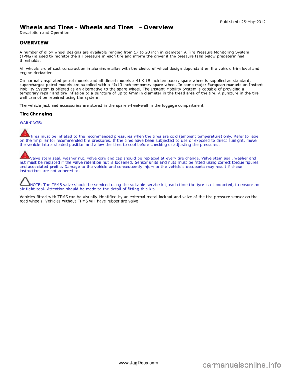
Wheels and Tires - Wheels and Tires - Overview
Description and Operation
OVERVIEW Published: 25-May-2012
A number of alloy wheel designs are available ranging from 17 to 20 inch in diameter. A Tire Pressure Monitoring System
(TPMS) is used to monitor the air pressure in each tire and inform the driver if the pressure falls below predetermined
thresholds.
All wheels are of cast construction in aluminum alloy with the choice of wheel design dependant on the vehicle trim level and
engine derivative.
On normally aspirated petrol models and all diesel models a 4J X 18 inch temporary spare wheel is supplied as standard,
supercharged petrol models are supplied with a 4Jx19 inch temporary spare wheel. In some major European markets an Instant
Mobility System is offered as an alternative to the spare wheel. The Instant Mobility System is capable of providing a
temporary repair and tire inflation to a puncture of up to 6mm in diameter in the tread area of the tire. A puncture in the tire
wall cannot be repaired using the system.
The vehicle jack and accessories are stored in the spare wheel-well in the luggage compartment.
Tire Changing
WARNINGS:
Tires must be inflated to the recommended pressures when the tires are cold (ambient temperature) only. Refer to label
on the 'B' pillar for recommended tire pressures. If the tires have been subjected to use or exposed to direct sunlight, move
the vehicle into a shaded position and allow the tires to cool before checking or adjusting the pressures.
Valve stem seal, washer nut, valve core and cap should be replaced at every tire change. Valve stem seal, washer and
nut must be replaced if the valve retention nut is loosened. Sensor units and nuts must be fitted using correct torque figures
and associated profile. Damage to the vehicle and consequently injury to the vehicle's occupants may result if these
instructions are not adhered to.
NOTE: The TPMS valve should be serviced using the suitable service kit, each time the tyre is dismounted, to ensure an
air tight seal. Attention should be made to the detail of fitting this kit.
Vehicles fitted with TPMS can be visually identified by an external metal locknut and valve of the tire pressure sensor on the
road wheels. Vehicles without TPMS will have rubber tire valve.
www.JagDocs.com
Page 443 of 3039

7 Initiators 8 TPMS module 9 Instrument cluster
Tire Pressure Monitoring System (TPMS) System Operation
The controlling software for the Tire Pressure Monitoring System (TPMS) is located within a Tire Pressure Monitoring System
Module. The software detects the following:
When the tire pressure is below the recommended low pressure value - under inflated tire.
The location of the tire on the vehicle that is below the recommended pressure.
Malfunction warning.
The TPMS system comprises:
Tire pressure monitoring system module located below the right-hand front seat.
Tire pressure receiver located near the gear shifter within the floor console.
Two front initiators positioned forward of the wheels and behind the fender splash shields.
Two rear initiators positioned rearward of the wheels and assembled on dedicated brackets located behind the fender
splash shields.
Four sensors, each sensor is integral with a tire valve and located within the tire; the space saver spare wheel is not
fitted with a sensor.
The four initiators are hard wired to the TPMS module. The initiators transmit 125 KHz Low Frequency (LF) signals to the tire
pressure sensors which respond by modifying the mode status within the Radio Frequency (RF) transmission. The 315 or 433
MHz RF signals are detected by the tire pressure receiver which is connected directly to the TPMS module. The received RF
signals from the tire pressure sensors are passed to the TPMS module and contain identification, pressure, temperature and
acceleration information for each wheel and tire.
The TPMS module communicates with the instrument cluster via the medium speed CAN bus to provide the driver with
appropriate warnings. The TPMS module also indicates status or failure of the TPMS or components.
Tire Location and Identification
The TPMS can identify the position of the wheels on the vehicle and assign a received tire pressure sensor identification to a
specific position on the vehicle, for example front left, front right, rear left and rear right. This feature is required because of
the different pressure targets and threshold that could exist between the front and rear tires.
The wheel location is performed automatically by the TPMS module using an 'auto-location' function. This function is fully
automatic and requires no input from the driver. The TPMS module automatically re-learns the position of the wheels on the
vehicle if the tire pressure sensors are replaced or the wheel positions on the vehicle are changed.
The TPMS software can automatically detect, under all operating conditions, the following:
one or more new tire pressure sensors have been fitted
one or more tire pressure sensors have stopped transmitting
TPMS module can reject identifications from tire pressure sensors which do not belong to the vehicle
two 'running' wheels on the vehicle have changed positions.
If a new tire pressure sensor is fitted on any 'running' wheel, the module can learn the new sensor identification automatically
through the tire learn and location process.
The tire-learn and location process is ready to commence when the vehicle has been stationary or traveling at less than 12
mph (20 km/h) for 15 minutes. This is known as 'parking mode'. The learn/locate process requires the vehicle to be driven at
speeds of more than 12 mph (20 km/h) for 15 minutes. If the vehicle speed reduces to below 12 mph (20 km/h), the learn
process timer is suspended until the vehicle speed increases to more than 12 mph (20 km/h), after which time the timer is
resumed. If the vehicle speed remains below 12 mph (20 km/h) for more than 15 minutes, the timer is set to zero and process
starts again.
Low Pressure Monitoring
The tire low pressure sensor transmits by RF (315 MHz or 433 MHz depending on market) signal. These signals contain data
which corresponds to tire low pressure sensor identification, tire pressure, tire temperature, acceleration and tire low pressure
sensor mode.
Each time the vehicle is driven, the tire pressure monitoring system module activates each LF antenna in turn. The
corresponding tire low pressure sensor detects the LF signal and responds by modifying the mode status within the RF
transmission.
The system enters 'parking mode' after the vehicle speed has been less than 20 km/h (12.5 miles/h) for 12 minutes. In parking
mode the tire low pressure sensors transmit a coded signal to the tire pressure monitoring system module once every 13
hours. If the tire pressure decreases by more than 0.06 bar (1 lbf/in²) the tire low pressure sensor will transmit more often as
pressure is lost.
As each wheel responds to the LF signal from the tire pressure monitoring system module, it is assigned a position on the
vehicle and is monitored for the remainder of that drive cycle in that position.
Page 446 of 3039
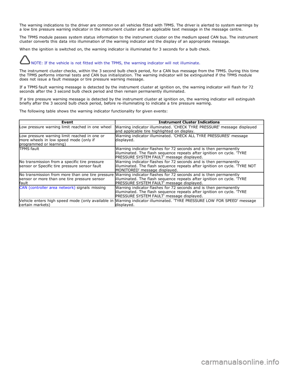
The warning indications to the driver are common on all vehicles fitted with TPMS. The driver is alerted to system warnings by
a low tire pressure warning indicator in the instrument cluster and an applicable text message in the message centre.
The TPMS module passes system status information to the instrument cluster on the medium speed CAN bus. The instrument
cluster converts this data into illumination of the warning indicator and the display of an appropriate message.
When the ignition is switched on, the warning indicator is illuminated for 3 seconds for a bulb check.
NOTE: If the vehicle is not fitted with the TPMS, the warning indicator will not illuminate.
The instrument cluster checks, within the 3 second bulb check period, for a CAN bus message from the TPMS. During this time
the TPMS performs internal tests and CAN bus initialization. The warning indicator will be extinguished if the TPMS module
does not issue a fault message or tire pressure warning message.
If a TPMS fault warning message is detected by the instrument cluster at ignition on, the warning indicator will flash for 72
seconds after the 3 second bulb check period and then remain permanently illuminated.
If a tire pressure warning message is detected by the instrument cluster at ignition on, the warning indicator will extinguish
briefly after the 3 second bulb check period, before re-illuminating to indicate a tire pressure warning.
The following table shows the warning indicator functionality for given events:
Event Instrument Cluster Indications Low pressure warning limit reached in one wheel
Warning indicator illuminated. 'CHECK TYRE PRESSURE' message displayed
and applicable tire highlighted on display. Low pressure warning limit reached in one or
more wheels in low speed mode (only if programmed or learning) Warning indicator illuminated. 'CHECK ALL TYRE PRESSURES' message
displayed. TPMS fault
Warning indicator flashes for 72 seconds and is then permanently
illuminated. The flash sequence repeats after ignition on cycle. 'TYRE
PRESSURE SYSTEM FAULT' message displayed. No transmission from a specific tire pressure
sensor or Specific tire pressure sensor fault Warning indicator flashes for 72 seconds and is then permanently
illuminated. The flash sequence repeats after ignition on cycle. 'TYRE NOT
MONITORED' message displayed. No transmission from more than one tire pressure
sensor or more than one tire pressure sensor
fault Warning indicator flashes for 72 seconds and is then permanently
illuminated. The flash sequence repeats after ignition on cycle. 'TYRE
PRESSURE SYSTEM FAULT' message displayed. CAN (controller area network) signals missing
Warning indicator flashes for 72 seconds and is then permanently
illuminated. The flash sequence repeats after ignition on cycle. 'TYRE
PRESSURE SYSTEM FAULT' message displayed. Vehicle enters high speed mode (only available in
certain markets) Warning indicator illuminated. 'TYRE PRESSURE LOW FOR SPEED' message displayed.
Page 468 of 3039
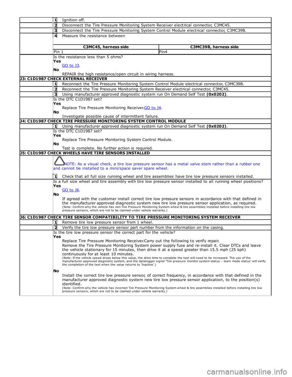
1 Ignition off. 2 Disconnect the Tire Pressure Monitoring System Receiver electrical connector, C3MC45. 3 Disconnect the Tire Pressure Monitoring System Control Module electrical connector, C3MC39B. 4 Measure the resistance between C3MC45, harness side C3MC39B, harness side Pin 1 Pin4 Is the resistance less than 5 ohms? Yes
GO to J3. No
REPAIR the high resistance/open circuit in wiring harness. J3: C1D1987 CHECK EXTERNAL RECEIVER 1 Reconnect the Tire Pressure Monitoring System Control Module electrical connector, C3MC39B. 2 Reconnect the Tire Pressure Monitoring System Receiver electrical connector, C3MC45. 3 Using manufacturer approved diagnostic system run On Demand Self Test (0x0202). Is the DTC C1D1987 set? Yes
Replace Tire Pressure Monitoring Receiver.GO to J4. No
Investigate possible cause of intermittent failure. J4: C1D1987 CHECK TIRE PRESSURE MONITORING SYSTEM CONTROL MODULE 1 Using manufacturer approved diagnostic system run On Demand Self Test (0x0202). Is the DTC C1D1987 set? Yes
Replace Tire Pressure Monitoring System Control Module.
No
Test is complete. No further action is required. J5: C1D1987 CHECK WHEELS HAVE TIRE SENSORS INSTALLED
NOTE: As a visual check, a tire low pressure sensor has a metal valve stem rather than a rubber one
and cannot be installed to a mini/space saver spare wheel. 1 Check that all full size running wheel and tire assemblies have tire low pressure sensors installed. Is a full size wheel and tire assembly with tire low pressure sensor installed to all running wheel positions? Yes
GO to J6. No
If agreed with the customer install correct tire low pressure sensors in accordance with that defined in
the manufacturer approved diagnostic system new tire low pressure sensor application, as required.
(Note: Confirm why the vehicle has non-Tire Pressure Monitoring System w he e l & tire assemblies installed before installing tire low
pressure sensors, which are not to be claimed under vehicle warranty.) J6: C1D1987 CHECK TIRE SENSOR COMPATIBILITY TO TIRE PRESSURE MONITORING SYSTEM RECEIVER 1 Remove tire low pressure sensor from 1 wheel. 2 Verify the tire low pressure sensor part number from the information on the casing. Is the tire low pressure sensor the correct part for the vehicle? Yes
Replace Tire Pressure Monitoring Receiver.Carry out the following to verify repair.
Remove the Tire Pressure Monitoring System power supply fuse and re-install it. Clear DTCs and leave
the vehicle stationary for 15 minutes, then drive it at a speed greater than 15.5 mph (25 kph)
continuously for at least 10 minutes.
(Note: If the vehicle spe e d drops below this value, the drive time to complete the test will need to be increased. The use of the manufacturer approved diagnostic system, and the datalogger signal ’Tire pressure monitor system status – learn mode status’ will verify the completion of the test w he n the value returns to ‘Inactive’.)
No
Install the correct tire low pressure sensor, of correct frequency, in accordance with that defined in the
manufacturer approved diagnostic system new tire low pressure sensor application, to the position(s)
identified.
(Note: Confirm why the vehicle has incorrect Tire Pressure Monitoring System w he e l & tire assemblies installed before installing tire low
pressure sensors, which are not to be claimed under vehicle warranty.)
Page 495 of 3039
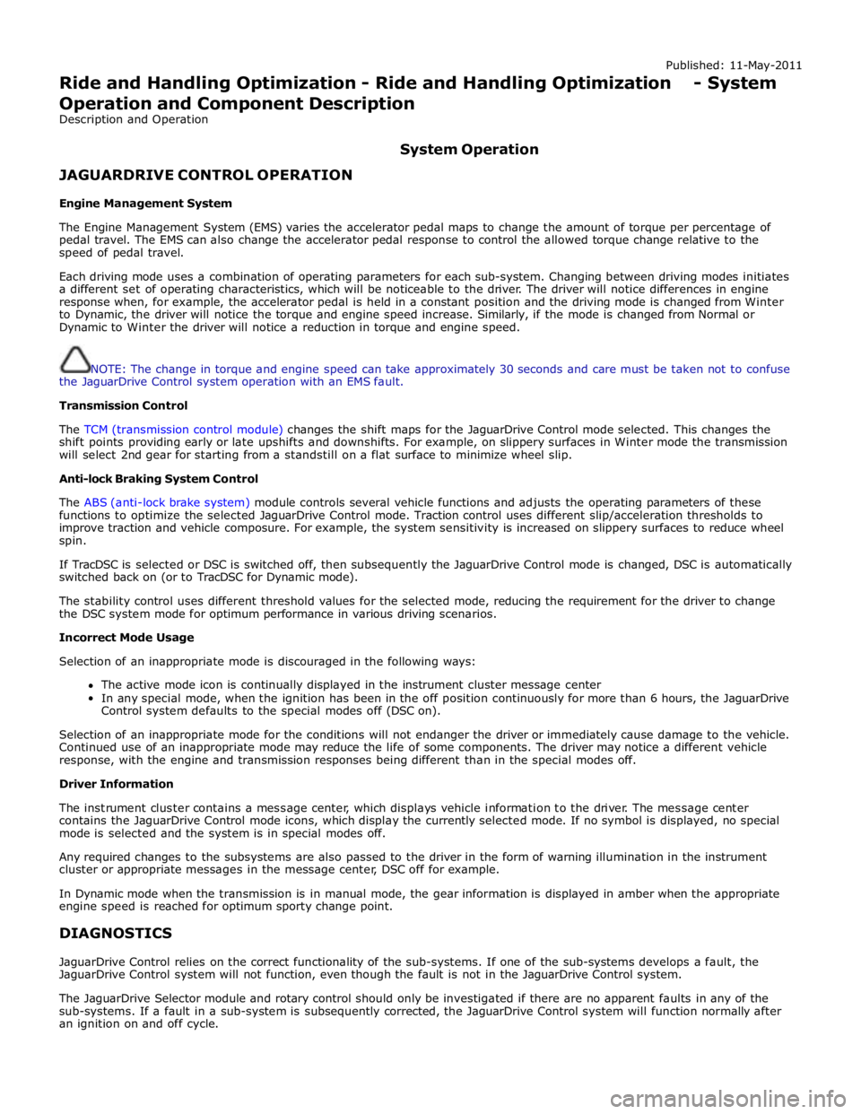
Published: 11-May-2011
Ride and Handling Optimization - Ride and Handling Optimization - System
Operation and Component Description
Description and Operation
JAGUARDRIVE CONTROL OPERATION
Engine Management System System Operation
The Engine Management System (EMS) varies the accelerator pedal maps to change the amount of torque per percentage of
pedal travel. The EMS can also change the accelerator pedal response to control the allowed torque change relative to the
speed of pedal travel.
Each driving mode uses a combination of operating parameters for each sub-system. Changing between driving modes initiates
a different set of operating characteristics, which will be noticeable to the driver. The driver will notice differences in engine
response when, for example, the accelerator pedal is held in a constant position and the driving mode is changed from Winter
to Dynamic, the driver will notice the torque and engine speed increase. Similarly, if the mode is changed from Normal or
Dynamic to Winter the driver will notice a reduction in torque and engine speed.
NOTE: The change in torque and engine speed can take approximately 30 seconds and care must be taken not to confuse
the JaguarDrive Control system operation with an EMS fault.
Transmission Control
The TCM (transmission control module) changes the shift maps for the JaguarDrive Control mode selected. This changes the
shift points providing early or late upshifts and downshifts. For example, on slippery surfaces in Winter mode the transmission
will select 2nd gear for starting from a standstill on a flat surface to minimize wheel slip.
Anti-lock Braking System Control
The ABS (anti-lock brake system) module controls several vehicle functions and adjusts the operating parameters of these
functions to optimize the selected JaguarDrive Control mode. Traction control uses different slip/acceleration thresholds to
improve traction and vehicle composure. For example, the system sensitivity is increased on slippery surfaces to reduce wheel
spin.
If TracDSC is selected or DSC is switched off, then subsequently the JaguarDrive Control mode is changed, DSC is automatically
switched back on (or to TracDSC for Dynamic mode).
The stability control uses different threshold values for the selected mode, reducing the requirement for the driver to change
the DSC system mode for optimum performance in various driving scenarios.
Incorrect Mode Usage
Selection of an inappropriate mode is discouraged in the following ways:
The active mode icon is continually displayed in the instrument cluster message center
In any special mode, when the ignition has been in the off position continuously for more than 6 hours, the JaguarDrive
Control system defaults to the special modes off (DSC on).
Selection of an inappropriate mode for the conditions will not endanger the driver or immediately cause damage to the vehicle.
Continued use of an inappropriate mode may reduce the life of some components. The driver may notice a different vehicle
response, with the engine and transmission responses being different than in the special modes off.
Driver Information
The instrument cluster contains a message center, which displays vehicle information to the driver. The message center
contains the JaguarDrive Control mode icons, which display the currently selected mode. If no symbol is displayed, no special
mode is selected and the system is in special modes off.
Any required changes to the subsystems are also passed to the driver in the form of warning illumination in the instrument
cluster or appropriate messages in the message center, DSC off for example.
In Dynamic mode when the transmission is in manual mode, the gear information is displayed in amber when the appropriate
engine speed is reached for optimum sporty change point.
DIAGNOSTICS
JaguarDrive Control relies on the correct functionality of the sub-systems. If one of the sub-systems develops a fault, the
JaguarDrive Control system will not function, even though the fault is not in the JaguarDrive Control system.
The JaguarDrive Selector module and rotary control should only be investigated if there are no apparent faults in any of the
sub-systems. If a fault in a sub-system is subsequently corrected, the JaguarDrive Control system will function normally after
an ignition on and off cycle.
Page 496 of 3039
JaguarDrive Control Sub-System Faults
If a fault occurs in a sub-system, the driver is alerted by the illumination of a warning indicator and/or an appropriate message
for that sub-system in the instrument cluster message center. No JaguarDrive Control message will be shown when a failed
sub-system displays its own message.
When a sub-system fault is present and the driver attempts to select a different JaguarDrive Control mode or at the next
ignition on cycle, a message 'WINTER MODE FAULT' or 'DYNAMIC MODE FAULT' will appear in the message center. This
generally implies that the JaguarDrive Control system has a fault, but only because a sub-system fault is preventing its
operation. This message will be displayed once per ignition cycle, but is repeated if a further selection is made by the driver
using the JaguarDrive Control buttons or at the next ignition on cycle.
NOTE: The message 'WINTER MODE FAULT' or 'DYNAMIC MODE FAULT' can also in very rare circumstances be generated
by a fault in the JaguarDrive Control module.
It is not possible for the JaguarDrive Control module to cause any fault behavior (warning indicator illumination or message
generation) in any of the sub-systems. Illumination of a sub-system warning indicator and/or a sub-system related message
will never be associated with a JaguarDrive Control module or JaguarDrive Control system fault.
The sub-system control modules can detect a fault with the CAN (controller area network) bus signal from the transmission
selector module. If a fault in the JaguarDrive Control system is detected, the sub-system control modules will operate in the
'special modes off' setting. The sub-system control modules will record a fault code for a failure of the JaguarDrive Control CAN signal. These faults can be retrieved using the Jaguar approved diagnostic tool and will provide useful information to indicate
investigation of the JaguarDrive Selector module or the CAN bus network. JaguarDrive Control System or Control Module Fault
If a fault occurs in the JaguarDrive Control system, all button icon LED (light emitting diode)'s will be turned off (background
illumination will remain on) and pressing of the JaguarDrive Control buttons is ignored. The instrument cluster message center
will display a message 'WINTER MODE FAULT' or 'DYNAMIC MODE FAULT' when the fault occurs, if the fault is present and the
driver attempts to select a special mode (if the control module is able to do this) or at the next ignition on cycle.
The JaguarDrive Control buttons and control module (JaguarDrive Selector module) are an integral unit. If a fault occurs in
either component, the whole unit will require replacement, however, this is extremely unlikely.
CAN Bus Faults
If a CAN bus fault exists and prevents JaguarDrive Control system operation, all of the JaguarDrive Control button icon LED's will be illuminated and rotation pressing of the JaguarDrive Control buttons is ignored.
If the instrument cluster does not receive a JaguarDrive Control system CAN bus message from the JaguarDrive Control module, the message 'SPECIAL MODE UNAVAILABLE' will be displayed when the fault occurs and will be repeated at every
ignition on cycle.
User Error
A special mode change while DSC or ABS is active (this includes ABS cycling) may be misinterpreted as a system fault.
Page 498 of 3039
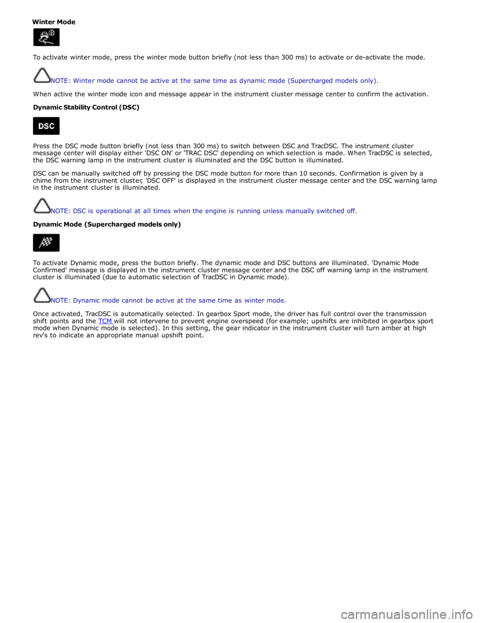
Winter Mode
To activate winter mode, press the winter mode button briefly (not less than 300 ms) to activate or de-activate the mode.
NOTE: Winter mode cannot be active at the same time as dynamic mode (Supercharged models only).
When active the winter mode icon and message appear in the instrument cluster message center to confirm the activation.
Dynamic Stability Control (DSC)
Press the DSC mode button briefly (not less than 300 ms) to switch between DSC and TracDSC. The instrument cluster
message center will display either 'DSC ON' or 'TRAC DSC' depending on which selection is made. When TracDSC is selected,
the DSC warning lamp in the instrument cluster is illuminated and the DSC button is illuminated.
DSC can be manually switched off by pressing the DSC mode button for more than 10 seconds. Confirmation is given by a
chime from the instrument cluster, 'DSC OFF' is displayed in the instrument cluster message center and the DSC warning lamp
in the instrument cluster is illuminated.
NOTE: DSC is operational at all times when the engine is running unless manually switched off.
Dynamic Mode (Supercharged models only)
To activate Dynamic mode, press the button briefly. The dynamic mode and DSC buttons are illuminated. 'Dynamic Mode
Confirmed' message is displayed in the instrument cluster message center and the DSC off warning lamp in the instrument
cluster is illuminated (due to automatic selection of TracDSC in Dynamic mode).
NOTE: Dynamic mode cannot be active at the same time as winter mode.
Once activated, TracDSC is automatically selected. In gearbox Sport mode, the driver has full control over the transmission
shift points and the TCM will not intervene to prevent engine overspeed (for example; upshifts are inhibited in gearbox sport mode when Dynamic mode is selected). In this setting, the gear indicator in the instrument cluster will turn amber at high
rev's to indicate an appropriate manual upshift point.
Page 537 of 3039

bus allows the DLM to communicate with other systems on the vehicle.
A certain amount of differential slip is required to allow the vehicle to turn corners and to remain stable under control of the
ABS. The ADM monitors the driver's demands through primary vehicle controls and automatically sets the slip torque in the differential. The system is completely automatic and does not require any special driver input.
The differential strategy in the ADM includes:
A pre-loading function, increasing locking torque with increased driving torque.
A slip controller to decrease locking torque for optimum comfort, e.g. parking.
The ADM memorizes the position of the motor when the ignition is switched off.
CAN bus messages used by the ADM include wheel speed, steering angle, automatic transmission speed, temperature information, car configuration, axle ratios and mode inputs.
The ADM also sends messages via the CAN bus to tell other control modules on the network the status of the electronic differential. The clutch torque and default mode status are some of the main signals sent out by the ADM.
If the DLM or ADM are replaced, a Jaguar approved diagnostic system must be connected to the vehicle and the differential
self-calibration procedure must be performed. This procedure must also be performed if the motor or electronic differential is
replaced.
If a fault occurs with the electronic differential, the ADM, the DLM, or one of the required input signals, the ADM records an
error code and displays a warning in the message center.
The following messages can be displayed:
Message Description Chime E-DIFF NOT
AVAILABLE Differential temperature has reached the overheat threshold. System deactivated until temperature
returns within limits. Single E-DIFF FAULT Fault has occurred with electronic differential. System deactivated until fault rectified. Single
Page 581 of 3039
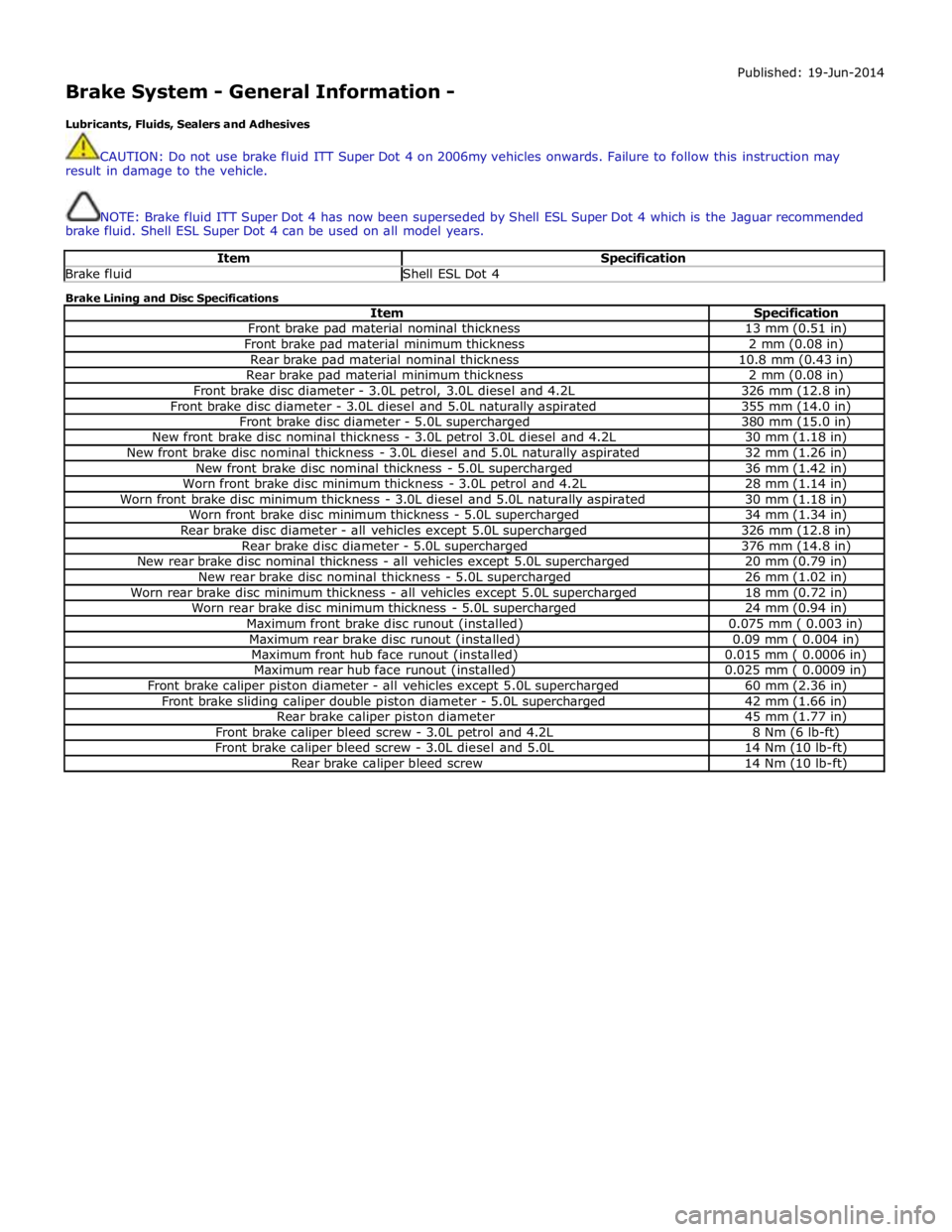
Brake System - General Information -
Lubricants, Fluids, Sealers and Adhesives Published: 19-Jun-2014
CAUTION: Do not use brake fluid ITT Super Dot 4 on 2006my vehicles onwards. Failure to follow this instruction may
result in damage to the vehicle.
NOTE: Brake fluid ITT Super Dot 4 has now been superseded by Shell ESL Super Dot 4 which is the Jaguar recommended
brake fluid. Shell ESL Super Dot 4 can be used on all model years.
Item Specification Brake fluid Shell ESL Dot 4 Brake Lining and Disc Specifications
Item Specification Front brake pad material nominal thickness 13 mm (0.51 in) Front brake pad material minimum thickness 2 mm (0.08 in) Rear brake pad material nominal thickness 10.8 mm (0.43 in) Rear brake pad material minimum thickness 2 mm (0.08 in) Front brake disc diameter - 3.0L petrol, 3.0L diesel and 4.2L 326 mm (12.8 in) Front brake disc diameter - 3.0L diesel and 5.0L naturally aspirated 355 mm (14.0 in) Front brake disc diameter - 5.0L supercharged 380 mm (15.0 in) New front brake disc nominal thickness - 3.0L petrol 3.0L diesel and 4.2L 30 mm (1.18 in) New front brake disc nominal thickness - 3.0L diesel and 5.0L naturally aspirated 32 mm (1.26 in) New front brake disc nominal thickness - 5.0L supercharged 36 mm (1.42 in) Worn front brake disc minimum thickness - 3.0L petrol and 4.2L 28 mm (1.14 in) Worn front brake disc minimum thickness - 3.0L diesel and 5.0L naturally aspirated 30 mm (1.18 in) Worn front brake disc minimum thickness - 5.0L supercharged 34 mm (1.34 in) Rear brake disc diameter - all vehicles except 5.0L supercharged 326 mm (12.8 in) Rear brake disc diameter - 5.0L supercharged 376 mm (14.8 in) New rear brake disc nominal thickness - all vehicles except 5.0L supercharged 20 mm (0.79 in) New rear brake disc nominal thickness - 5.0L supercharged 26 mm (1.02 in) Worn rear brake disc minimum thickness - all vehicles except 5.0L supercharged 18 mm (0.72 in) Worn rear brake disc minimum thickness - 5.0L supercharged 24 mm (0.94 in) Maximum front brake disc runout (installed) 0.075 mm ( 0.003 in) Maximum rear brake disc runout (installed) 0.09 mm ( 0.004 in) Maximum front hub face runout (installed) 0.015 mm ( 0.0006 in) Maximum rear hub face runout (installed) 0.025 mm ( 0.0009 in) Front brake caliper piston diameter - all vehicles except 5.0L supercharged 60 mm (2.36 in) Front brake sliding caliper double piston diameter - 5.0L supercharged 42 mm (1.66 in) Rear brake caliper piston diameter 45 mm (1.77 in) Front brake caliper bleed screw - 3.0L petrol and 4.2L 8 Nm (6 lb-ft) Front brake caliper bleed screw - 3.0L diesel and 5.0L 14 Nm (10 lb-ft) Rear brake caliper bleed screw 14 Nm (10 lb-ft)