SECURITY SYSTEM JAGUAR XFR 2010 1.G User Guide
[x] Cancel search | Manufacturer: JAGUAR, Model Year: 2010, Model line: XFR, Model: JAGUAR XFR 2010 1.GPages: 3039, PDF Size: 58.49 MB
Page 185 of 3039
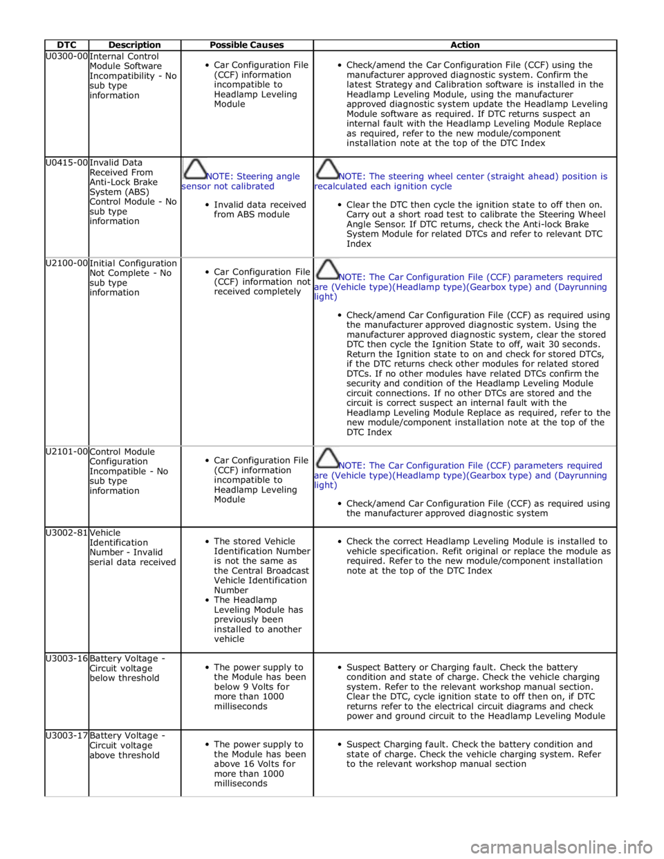
DTC Description Possible Causes Action U0300-00
Internal Control
Module Software
Incompatibility - No
sub type
information
Car Configuration File
(CCF) information
incompatible to
Headlamp Leveling
Module
Check/amend the Car Configuration File (CCF) using the
manufacturer approved diagnostic system. Confirm the
latest Strategy and Calibration software is installed in the
Headlamp Leveling Module, using the manufacturer
approved diagnostic system update the Headlamp Leveling
Module software as required. If DTC returns suspect an
internal fault with the Headlamp Leveling Module Replace
as required, refer to the new module/component
installation note at the top of the DTC Index U0415-00
Invalid Data
Received From
Anti-Lock Brake
System (ABS)
Control Module - No
sub type
information
NOTE: Steering angle
sensor not calibrated
Invalid data received
from ABS module
NOTE: The steering wheel center (straight ahead) position is
recalculated each ignition cycle
Clear the DTC then cycle the ignition state to off then on.
Carry out a short road test to calibrate the Steering Wheel
Angle Sensor. If DTC returns, check the Anti-lock Brake
System Module for related DTCs and refer to relevant DTC
Index U2100-00
Initial Configuration
Not Complete - No
sub type
information
Car Configuration File
(CCF) information not
received completely
NOTE: The Car Configuration File (CCF) parameters required
are (Vehicle type)(Headlamp type)(Gearbox type) and (Dayrunning
light)
Check/amend Car Configuration File (CCF) as required using
the manufacturer approved diagnostic system. Using the
manufacturer approved diagnostic system, clear the stored
DTC then cycle the Ignition State to off, wait 30 seconds.
Return the Ignition state to on and check for stored DTCs,
if the DTC returns check other modules for related stored
DTCs. If no other modules have related DTCs confirm the
security and condition of the Headlamp Leveling Module
circuit connections. If no other DTCs are stored and the
circuit is correct suspect an internal fault with the
Headlamp Leveling Module Replace as required, refer to the
new module/component installation note at the top of the
DTC Index U2101-00
Control Module
Configuration
Incompatible - No
sub type
information
Car Configuration File
(CCF) information
incompatible to
Headlamp Leveling
Module
NOTE: The Car Configuration File (CCF) parameters required
are (Vehicle type)(Headlamp type)(Gearbox type) and (Dayrunning
light)
Check/amend Car Configuration File (CCF) as required using
the manufacturer approved diagnostic system U3002-81
Vehicle
Identification
Number - Invalid
serial data received
The stored Vehicle
Identification Number
is not the same as
the Central Broadcast
Vehicle Identification
Number
The Headlamp
Leveling Module has
previously been
installed to another
vehicle
Check the correct Headlamp Leveling Module is installed to
vehicle specification. Refit original or replace the module as
required. Refer to the new module/component installation
note at the top of the DTC Index U3003-16
Battery Voltage -
Circuit voltage
below threshold
The power supply to
the Module has been
below 9 Volts for
more than 1000
milliseconds
Suspect Battery or Charging fault. Check the battery
condition and state of charge. Check the vehicle charging
system. Refer to the relevant workshop manual section.
Clear the DTC, cycle ignition state to off then on, if DTC
returns refer to the electrical circuit diagrams and check
power and ground circuit to the Headlamp Leveling Module U3003-17
Battery Voltage -
Circuit voltage
above threshold
The power supply to
the Module has been
above 16 Volts for
more than 1000
milliseconds
Suspect Charging fault. Check the battery condition and
state of charge. Check the vehicle charging system. Refer
to the relevant workshop manual section
Page 211 of 3039

DTC Description Possible Causes Action bumper that is not reporting a fault. Clear the DTC
and run the on demand self test to confirm if the
fault code now appears for the new position of the
suspect sensor. Renew the faulty sensor B1B50-01 Rear Left Inner Sensor
- General electrical
failure
Wiring harness fault
Rear Left Inner Sensor -
Component internal
failure
Refer to electrical wiring diagrams and check the rear
bumper harness for damage/corrosion. Check sensor
circuit for short circuit to ground, short circuit to
power, open circuit. Repair or replace any wiring
harness as required
Check the connector for integrity and damage, then
re-connect sensor to confirm connection
Using the manufacturers approved diagnostic system
clear the DTC and run the on demand self test
If the problem persists remove the suspect sensor
from the bumper. Inspect the sensor connector for
signs of water ingress/corrosion. Exchange the
suspect sensor with another sensor within the
bumper that is not reporting a fault. Clear the DTC
and run the on demand self test to confirm if the
fault code now appears for the new position of the
suspect sensor. Renew the faulty sensor B1B50-12 Rear Left Inner Sensor
- Circuit short to
battery
Wiring harness fault
Refer to electrical wiring diagrams and check the rear
bumper harness for damage. Check sensor circuit for
short circuit to power. Repair or replace any wiring
harness as required
Check the connector for integrity and damage, then
re-connect sensor to confirm connection
Using the manufacturers approved diagnostic system
clear the DTC and run the on demand self test B1B50-96 Rear Left Inner Sensor
- Component internal
failure
Wiring harness fault
Rear Left Inner Sensor -
Component internal
failure
Refer to electrical wiring diagrams and check the rear
bumper harness for damage/corrosion. Check sensor
circuit for short circuit to ground, short circuit to
power, open circuit. Repair or replace any wiring
harness as required
Check the connector for integrity and damage, then
re-connect sensor to confirm connection
Using the manufacturers approved diagnostic system
clear the DTC and run the on demand self test
If the problem persists remove the suspect sensor
from the bumper. Inspect the sensor connector for
signs of water ingress/corrosion. Exchange the
suspect sensor with another sensor within the
bumper that is not reporting a fault. Clear the DTC
and run the on demand self test to confirm if the
fault code now appears for the new position of the
suspect sensor. Renew the faulty sensor B1B54-11 Function LED - Park Aid
- Circuit short to
ground
Wiring harness fault
Switch/LED - Component
internal failure
Refer to electrical wiring diagrams and check the
parking aid LED circuit for short circuit to ground.
Repair or replace any wiring harness as required
Using the manufacturers approved diagnostic system
clear the DTC and run the on demand self test. If the
problem persists, suspect the switch/LED B1B54-12 Function LED - Park Aid
- Circuit short to
battery
Wiring harness fault
Switch/LED - Component
internal failure
Control Module -
Component internal
failure
Refer to electrical wiring diagrams and check the
parking aid LED circuit for short circuit to power.
Repair or replace any wiring harness as required
Using the manufacturers approved diagnostic system
clear the DTC and run the on demand self test. If the
problem persists, suspect the switch/LED B1B57-11
Front Sensors Power
Circuit- Circuit short to
ground
Wiring harness fault
Control Module -
Component internal
failure
Check front and rear bumper harness for signs of
damage and security of connections
Refer to electrical wiring diagrams and check the
parking assist front sensor power circuit and rear
sensor power circuit for short circuit to ground. Repair
or replace any wiring harness as required
Using the manufacturers approved diagnostic system
clear the DTC and run the on demand self test. If the
problem persists, suspect the control module www.JagDocs.com
Page 212 of 3039

DTC Description Possible Causes Action Cycle the ignition off, then on, to power up parking
aid system and check corrective action B1B58-11
Rear Sensors Power
Circuit - Circuit short
to ground
Wiring harness fault
Control Module -
Component internal
failure
Check rear and front (if front PDC fitted) bumper
harness for signs of damage and security of
connections
Refer to electrical wiring diagrams and check the
parking assist rear sensor power circuit and front
sensor power circuit (if front PDC fitted) for short
circuit to ground. Repair or replace any wiring harness
as required
Using the manufacturers approved diagnostic system
clear the DTC and run the on demand self test. If the
problem persists, suspect the control module
Cycle the ignition off, then on, to power up parking
aid system and check corrective action B1C30-73
Disable Switch -
Actuator stuck closed
Wiring harness fault
Control Switch -
Component internal
failure
Refer to electrical wiring diagrams and check the
parking assist switch and switch circuit. Repair or
replace any wiring harness as required
Using the manufacturers approved diagnostic system
clear the DTC and run the on demand self test. If the
problem persists, suspect the control switch
Check the switch function U0010-00
Medium Speed CAN
Communication Bus -
No sub type
information
Medium speed CAN
failure - bus off
Refer to the electrical circuit diagrams and check the
parking aid control module medium speed CAN bus
for short circuit to ground, short circuit to power,
open circuit, high resistance, or short circuit between
the paired CAN wires
Using the manufacturer approved diagnostic system,
complete a CAN network integrity test
Cycle the ignition off, then on, and check if the DTC
is still logged U0073-00
Control Module
Communication Bus
"A" Off - No sub type
information
Control module
communication Bus "A"
failure - bus off
Refer to the electrical circuit diagrams and check the
parking aid control module high speed CAN bus for
short circuit to ground, short circuit to power, open
circuit, high resistance, or short circuit between the
paired CAN wires
Using the manufacturer approved diagnostic system,
complete a CAN network integrity test
Cycle the ignition off, then on, and check if the DTC
is still logged U0140-00
Lost Communication
With Body Control
Module - No sub type
information
Loss of CAN
communication with
central junction box
Refer to the electrical circuit diagrams and check the
power and ground connections to the central junction
box. Clear DTC and retest
Using the manufacturer approved diagnostic system,
complete a CAN network integrity test. Refer to the
electrical circuit diagrams and check the CAN network
between the central junction box and the parking aid
control module U0142-00 Lost Communication
Loss of CAN
Refer to the electrical circuit diagrams and check the With Body Control Module "B" - No sub communication with power and ground connections to the auxiliary type information auxiliary junction box junction box. Clear DTC and retest Using the manufacturer approved diagnostic system, complete a CAN network integrity test. Refer to the electrical circuit diagrams and check the CAN network between the central junction box and the parking aid control module U0155-00
Lost Communication
With Instrument Panel
Cluster (IPC) Control
Module - No sub type
information
Loss of CAN
communication with
instrument cluster
Refer to the electrical circuit diagrams and check the
power and ground connections to the instrument
cluster. Clear DTC and retest
Using the manufacturer approved diagnostic system,
complete a CAN network integrity test. Refer to the
electrical circuit diagrams and check the CAN network
between the central junction box and the parking aid
control module
Page 217 of 3039

DTC Description Possible Causes Action prior approval programme is in operation, prior to
the installation of a new module/component P0606-00
Control Module
Processor - No sub type
information
Watchdog reset - internal
control module failure
This is a control module internal check DTC. If no
other DTCs are logged and no customer complaint
exists, clear/ignore this DTC. If the problem
persists, renew the control module. Refer to the
warranty policy and procedures manual, or
determine if any prior approval programme is in
operation, prior to the installation of a new
module/component P0607-00
Control Module
Performance - No sub
type information
Rear differential control
module internal error -
charge pump voltage
below threshold
Clear the DTC and retest. If the problem persists,
renew the control module. Refer to the warranty
policy and procedures manual, or determine if any
prior approval programme is in operation, prior to
the installation of a new module/component P0652-00
Sensor Reference
Voltage B Circuit Low -
No sub type
information
Position sensor supply
below 5.7V
Sensor failure (within
actuator)
Refer to the electrical circuit diagrams and check
the differential actuator sensor position circuit,
repair as necessary. Clear the DTC and retest
If no circuit problems exist, renew the differential
actuator. Refer to the warranty policy and
procedures manual, or determine if any prior
approval programme is in operation, prior to the
installation of a new module/component P0653-00
Sensor Reference
Voltage B Circuit High -
No sub type
information
Motor position sensor
supply above 8.3 V
Internal control module
failure
Refer to the electrical circuit diagrams and check
the differential actuator hall sensor reference
voltage at the control module or the actuator
If voltage is too high, then renew control module.
Refer to the warranty policy and procedures
manual, or determine if any prior approval
programme is in operation, prior to the installation
of a new module/component P0666-00 PCM / ECM / TCM
Internal Temperature
Sensor A Circuit - No
sub type information
Internal electronic control
unit temperature sensor
value above 105°C
This is a control module internal check DTC. If no
other DTCs are logged and no customer complaint
exists, clear this DTC and retest. Check the
security of control module fixings. Check the
module ground connection. Consider environmental
conditions before suspecting the control module. If
the problem persists, renew the control module.
Refer to the warranty policy and procedures
manual, or determine if any prior approval
programme is in operation, prior to the installation
of a new module/component P0702-64 Transmission Control
System Electrical -
Signal plausibility
failure
Implausibility of
differential motor
temperature sensor and
oil temperature sensor
readout detected
Motor or oil temperature
sensor circuit - short
circuit to ground or power
Check the rear differential oil quantity and
specification. Refer to the relevant section of the
workshop manual. Check both temperature sensor
circuits and connectors for damage/water ingress,
repair as necessary. Where available, after vehicle
has been switched off for at least an hour, use the
manufacturer approved diagnostic system to read
motor temperature and oil temperature sensor
values. Temperature difference should be less than
25°C. Clear the DTC and retest
Refer to the electrical circuit diagrams and check
motor temperature sensor and oil sump
temperature sensors and circuit for short circuit to
ground, short circuit to power P0712-00 Transmission Fluid Temperature Sensor A
Circuit Low - No sub
type information
Differential actuator
internal temperature
sensor circuit - open
circuit or short circuit to
ground
Refer to the electrical circuit diagrams and check
rear differential actuator motor temperature sensor
circuit for short circuit to ground, open circuit, high
resistance. Clear the DTC and retest. If no circuit
problems exist, renew the differential actuator.
Refer to the warranty policy and procedures
manual, or determine if any prior approval
programme is in operation, prior to the installation
of a new module/component
Page 296 of 3039
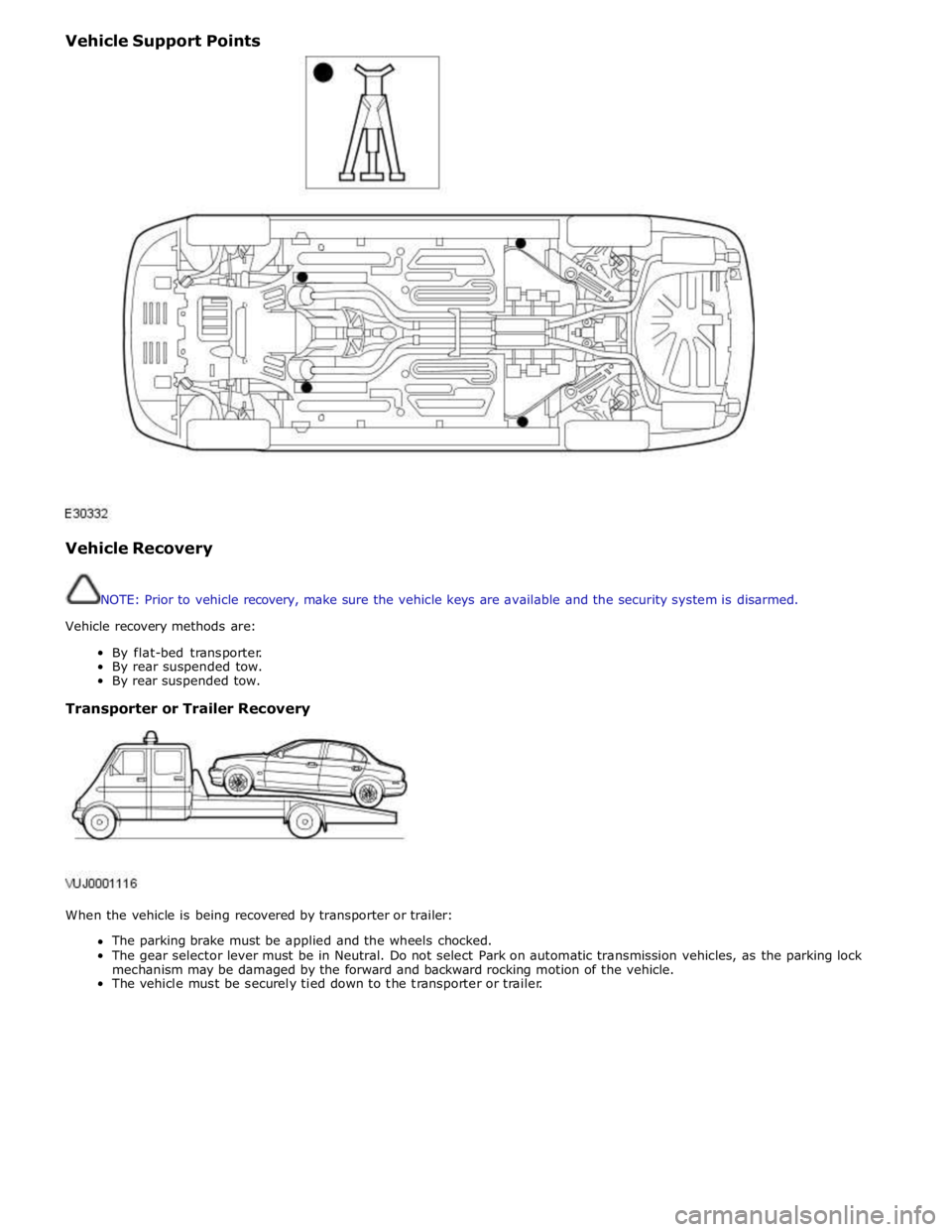
Vehicle Support Points
Vehicle Recovery
NOTE: Prior to vehicle recovery, make sure the vehicle keys are available and the security system is disarmed.
Vehicle recovery methods are:
By flat-bed transporter.
By rear suspended tow.
By rear suspended tow.
Transporter or Trailer Recovery
When the vehicle is being recovered by transporter or trailer:
The parking brake must be applied and the wheels chocked.
The gear selector lever must be in Neutral. Do not select Park on automatic transmission vehicles, as the parking lock
mechanism may be damaged by the forward and backward rocking motion of the vehicle.
The vehicle must be securely tied down to the transporter or trailer.
Page 303 of 3039
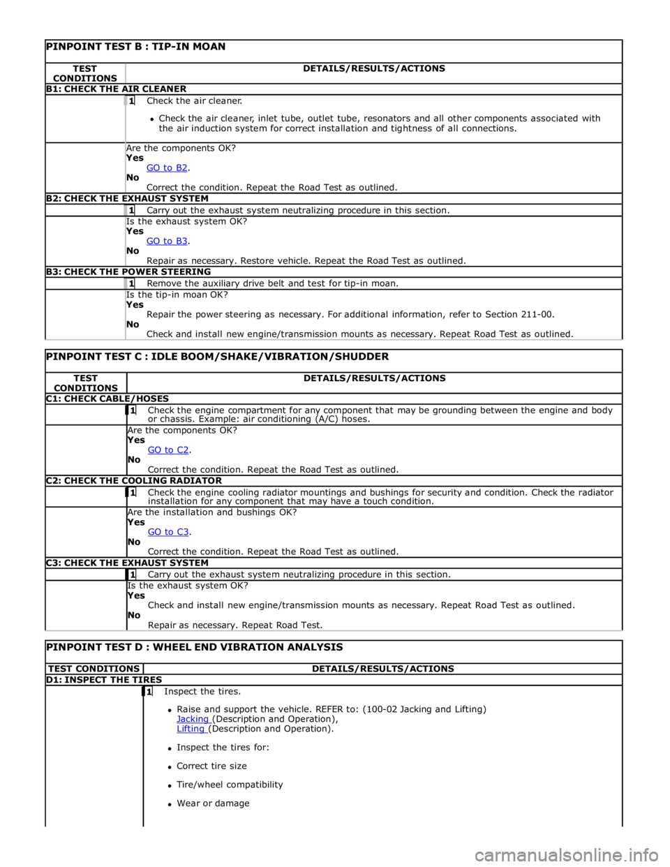
PINPOINT TEST B : TIP-IN MOAN TEST
CONDITIONS DETAILS/RESULTS/ACTIONS B1: CHECK THE AIR CLEANER 1 Check the air cleaner.
Check the air cleaner, inlet tube, outlet tube, resonators and all other components associated with
the air induction system for correct installation and tightness of all connections. Are the components OK? Yes
GO to B2. No
Correct the condition. Repeat the Road Test as outlined. B2: CHECK THE EXHAUST SYSTEM 1 Carry out the exhaust system neutralizing procedure in this section. Is the exhaust system OK? Yes
GO to B3. No
Repair as necessary. Restore vehicle. Repeat the Road Test as outlined. B3: CHECK THE POWER STEERING 1 Remove the auxiliary drive belt and test for tip-in moan. Is the tip-in moan OK? Yes
Repair the power steering as necessary. For additional information, refer to Section 211-00.
No
Check and install new engine/transmission mounts as necessary. Repeat Road Test as outlined.
PINPOINT TEST C : IDLE BOOM/SHAKE/VIBRATION/SHUDDER TEST
CONDITIONS DETAILS/RESULTS/ACTIONS C1: CHECK CABLE/HOSES 1 Check the engine compartment for any component that may be grounding between the engine and body or chassis. Example: air conditioning (A/C) hoses. Are the components OK? Yes
GO to C2. No
Correct the condition. Repeat the Road Test as outlined. C2: CHECK THE COOLING RADIATOR 1 Check the engine cooling radiator mountings and bushings for security and condition. Check the radiator installation for any component that may have a touch condition. Are the installation and bushings OK? Yes
GO to C3. No
Correct the condition. Repeat the Road Test as outlined. C3: CHECK THE EXHAUST SYSTEM 1 Carry out the exhaust system neutralizing procedure in this section. Is the exhaust system OK? Yes
Check and install new engine/transmission mounts as necessary. Repeat Road Test as outlined.
No
Repair as necessary. Repeat Road Test.
PINPOINT TEST D : WHEEL END VIBRATION ANALYSIS TEST CONDITIONS DETAILS/RESULTS/ACTIONS D1: INSPECT THE TIRES 1 Inspect the tires.
Raise and support the vehicle. REFER to: (100-02 Jacking and Lifting)
Jacking (Description and Operation), Lifting (Description and Operation).
Inspect the tires for:
Correct tire size
Tire/wheel compatibility
Wear or damage
Page 718 of 3039
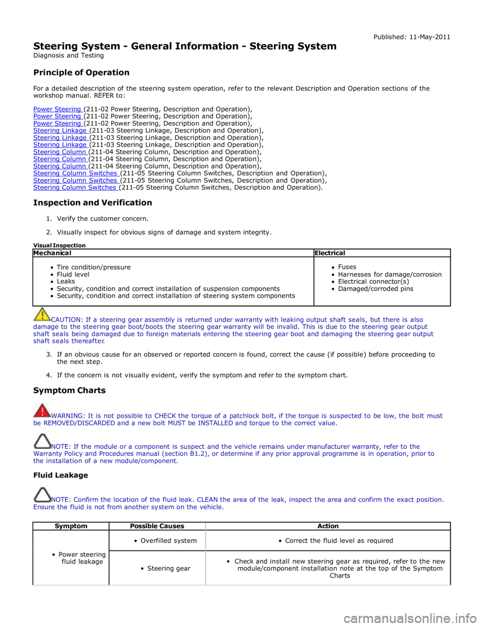
Steering System - General Information - Steering System
Diagnosis and Testing
Principle of Operation Published: 11-May-2011
For a detailed description of the steering system operation, refer to the relevant Description and Operation sections of the
workshop manual. REFER to:
Power Steering (211-02 Power Steering, Description and Operation), Power Steering (211-02 Power Steering, Description and Operation), Power Steering (211-02 Power Steering, Description and Operation), Steering Linkage (211-03 Steering Linkage, Description and Operation), Steering Linkage (211-03 Steering Linkage, Description and Operation), Steering Linkage (211-03 Steering Linkage, Description and Operation), Steering Column (211-04 Steering Column, Description and Operation), Steering Column (211-04 Steering Column, Description and Operation), Steering Column (211-04 Steering Column, Description and Operation), Steering Column Switches (211-05 Steering Column Switches, Description and Operation), Steering Column Switches (211-05 Steering Column Switches, Description and Operation), Steering Column Switches (211-05 Steering Column Switches, Description and Operation).
Inspection and Verification
1. Verify the customer concern.
2. Visually inspect for obvious signs of damage and system integrity.
Visual Inspection
Mechanical Electrical
Tire condition/pressure
Fluid level
Leaks
Security, condition and correct installation of suspension components
Security, condition and correct installation of steering system components
Fuses
Harnesses for damage/corrosion
Electrical connector(s)
Damaged/corroded pins
CAUTION: If a steering gear assembly is returned under warranty with leaking output shaft seals, but there is also
damage to the steering gear boot/boots the steering gear warranty will be invalid. This is due to the steering gear output
shaft seals being damaged due to foreign materials entering the steering gear boot and damaging the steering gear output
shaft seals thereafter.
3. If an obvious cause for an observed or reported concern is found, correct the cause (if possible) before proceeding to
the next step.
4. If the concern is not visually evident, verify the symptom and refer to the symptom chart.
Symptom Charts
WARNING: It is not possible to CHECK the torque of a patchlock bolt, if the torque is suspected to be low, the bolt must
be REMOVED/DISCARDED and a new bolt MUST be INSTALLED and torque to the correct value.
NOTE: If the module or a component is suspect and the vehicle remains under manufacturer warranty, refer to the
Warranty Policy and Procedures manual (section B1.2), or determine if any prior approval programme is in operation, prior to
the installation of a new module/component.
Fluid Leakage
NOTE: Confirm the location of the fluid leak. CLEAN the area of the leak, inspect the area and confirm the exact position.
Ensure the fluid is not from another system on the vehicle.
Symptom Possible Causes Action
Power steering
fluid leakage
Overfilled system
Correct the fluid level as required
Steering gear
Check and install new steering gear as required, refer to the new
module/component installation note at the top of the Symptom
Charts
Page 803 of 3039

automatically reset once the applicable remote handset has been detected by the vehicle security systems.
STEERING WHEEL HEATER
On certain models the rim of the steering wheel contains a heater element. Operation of the heater is selected using the
Touch Screen Display (TSD).
The heater temperature is controlled by a heated steering wheel control module located within the steering wheel. Power for
the heater element is supplied to the steering wheel via 2 contacts on the clockspring and a slip ring mounted on the steering
wheel.
Page 1299 of 3039
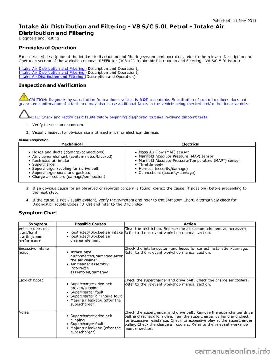
Published: 11-May-2011
Intake Air Distribution and Filtering - V8 S/C 5.0L Petrol - Intake Air
Distribution and Filtering
Diagnosis and Testing
Principles of Operation
For a detailed description of the intake air distribution and filtering system and operation, refer to the relevant Description and
Operation section of the workshop manual. REFER to: (303-12D Intake Air Distribution and Filtering - V8 S/C 5.0L Petrol)
Intake Air Distribution and Filtering (Description and Operation), Intake Air Distribution and Filtering (Description and Operation), Intake Air Distribution and Filtering (Description and Operation).
Inspection and Verification
CAUTION: Diagnosis by substitution from a donor vehicle is NOT acceptable. Substitution of control modules does not
guarantee confirmation of a fault and may also cause additional faults in the vehicle being checked and/or the donor vehicle.
NOTE: Check and rectify basic faults before beginning diagnostic routines involving pinpoint tests.
1. Verify the customer concern.
2. Visually inspect for obvious signs of mechanical or electrical damage.
Visual Inspection
Mechanical Electrical
Hoses and ducts (damage/connections)
Air cleaner element (contaminated/blocked)
Restricted air intake
Supercharger
Supercharger (cooling fan) drive belt
Supercharger seals and gaskets
Charge air coolers (damage/connection)
Mass Air Flow (MAF) sensor
Manifold Absolute Pressure (MAP) sensor
Manifold Absolute Pressure/Temperature (MAPT) sensor
Throttle body
Harness (security/damage)
Connections (security/damage)
3. If an obvious cause for an observed or reported concern is found, correct the cause (if possible) before proceeding to
the next step.
4. If the cause is not visually evident, verify the symptom and refer to the Symptom Chart, alternatively check for
Diagnostic Trouble Codes (DTCs) and refer to the DTC Index.
Symptom Chart
Symptom Possible Causes Action Vehicle does not
start/hard
starting/poor
performance
Restricted/Blocked air intake
Restricted/Blocked air
cleaner element Clear the restriction. Replace the air cleaner element as necessary.
Refer to the relevant workshop manual section. Excessive intake
noise
Intake pipe
disconnected/damaged after
the air cleaner
Air cleaner assembly
incorrectly
assembled/damaged Check the intake system and hoses for correct installation/damage.
Refer to the relevant workshop manual section. Lack of boost
Supercharger drive belt
broken/slipping
Supercharger fault
Supercharger air intake fault
Major air leakage (after the
supercharger) Check the supercharger and drive belt. Check the charge air coolers.
Refer to the relevant workshop manual section. Noise
Supercharger drive belt
slipping
Supercharger fault
Major air leakage (after the
supercharger) Check the supercharger and drive belt. Remove the supercharger drive
belt and recheck for noise. Turn the supercharger by hand and check
for excessive resistance. Check for excessive play at the supercharger
pulley. Check the charge air coolers. Refer to the relevant workshop
manual section.
Page 1369 of 3039
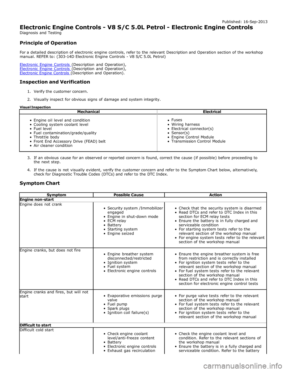
Published: 16-Sep-2013
Electronic Engine Controls - V8 S/C 5.0L Petrol - Electronic Engine Controls
Diagnosis and Testing
Principle of Operation
For a detailed description of electronic engine controls, refer to the relevant Description and Operation section of the workshop
manual. REFER to: (303-14D Electronic Engine Controls - V8 S/C 5.0L Petrol)
Electronic Engine Controls (Description and Operation), Electronic Engine Controls (Description and Operation), Electronic Engine Controls (Description and Operation).
Inspection and Verification
1. Verify the customer concern.
2. Visually inspect for obvious signs of damage and system integrity.
Visual Inspection
Mechanical Electrical
Engine oil level and condition
Cooling system coolant level
Fuel level
Fuel contamination/grade/quality
Throttle body
Front End Accessory Drive (FEAD) belt
Air cleaner condition
Fuses
Wiring harness
Electrical connector(s)
Sensor(s)
Engine Control Module
Transmission Control Module
3. If an obvious cause for an observed or reported concern is found, correct the cause (if possible) before proceeding to
the next step.
4. If the cause is not visually evident, verify the customer concern and refer to the Symptom Chart below, alternatively,
check for Diagnostic Trouble Codes (DTCs) and refer to the DTC Index.
Symptom Chart
Symptom Possible Cause Action Engine non-start Engine does not crank
Security system /Immobilizer
engaged
Engine in shut-down mode
ECM relay
Battery
Starting system
Engine seized
Check that the security system is disarmed
Read DTCs and refer to DTC Index in this
section for ECM relay tests
Ensure the battery is in fully charged and
serviceable condition
For starting system tests refer to the
relevant section of the workshop manual
For engine system tests refer to the relevant
section of the workshop manual Engine cranks, but does not fire
Engine breather system
disconnected/restricted
Ignition system
Fuel system
Electronic engine controls
Ensure the engine breather system is free
from restriction and is correctly installed
For ignition system tests refer to the
relevant section of the workshop manual
For fuel system tests refer to the relevant
section of the workshop manual
Read DTCs and refer to DTC Index in this
section for electronic engine control tests Engine cranks and fires, but will not
start
Evaporative emissions purge
valve
Fuel pump
Spark plugs
Ignition coil failure(s)
For purge valve tests refer to the relevant
section of the workshop manual
For fuel system tests refer to the relevant
section of the workshop manual
For ignition system tests refer to the
relevant section of the workshop manual Difficult to start Difficult cold start
Check engine coolant
level/anti-freeze content
Battery
Electronic engine controls
Exhaust gas recirculation
Check the engine coolant level and
condition. Refer to the relevant sections of
the workshop manual
Ensure the battery is in a fully charged and
serviceable condition. Refer to the battery