clock JAGUAR XFR 2010 1.G Workshop Manual
[x] Cancel search | Manufacturer: JAGUAR, Model Year: 2010, Model line: XFR, Model: JAGUAR XFR 2010 1.GPages: 3039, PDF Size: 58.49 MB
Page 30 of 3039

System Operation and Component DescriptionDiagnosis and TestingAir Bag and Safety Belt Pretensioner Supplemental Restraint System (SRS)General ProceduresAir Bag DisposalRemoval and InstallationB-Pillar Side Impact Sensor
Clockspring
C-Pillar Side Impact Sensor
Crash Sensor
Driver Air Bag Module
Occupant Classification Sensor
Passenger Air Bag Module
Restraints Control Module (RCM)
Side Air Bag Module (76.73.47)
Side Air Curtain Module501-20C: Pedestrian Protection System
Description and OperationComponent Location
Overview
System Operation and Component DescriptionDiagnosis and TestingPedestrian Protection SystemRemoval and InstallationPedestrian Impact Sensor
Pedestrian Protection Hood Actuator LH
Pedestrian Protection Hood Actuator RH
Pedestrian Protection Module501-25A: Body Repairs - General Information
Description and OperationBody Repairs501-25B: Body Repairs - Corrosion Protection
Description and OperationCorrosion Protection501-25C: Body Repairs - Water Leaks
Description and OperationWater Leaks501-26: Body Repairs - Vehicle Specific Information and Tolerance Checks
Description and OperationBody and Frame501-27: Front End Sheet Metal Repairs
Description and OperationFront End Sheet Metal
Page 50 of 3039
disconnected, a Radio Code Saver will allow sufficient current to pass to maintain the radio receiver/cassette player/mini disc
player and compact disc player memory, operate the clock and supply the door operated interior lights while isolating the
battery in the event of a short circuit.
Reconnecting the Battery
WARNING: If the battery has been on bench charge the cells may be giving off explosive hydrogen gas. Avoid creating
sparks, and if in doubt cover the vent plugs or covers with a damp cloth.
Always make sure that all electrical systems are switched OFF before reconnecting the battery to avoid causing sparks or
damage to sensitive electrical equipment.
Always reconnect the battery positive lead first and the negative last, ensuring that there is a good electrical contact and the
battery terminals are secure.
Restart the clock (where installed) and set it to the correct time.
Enter the radio receiver/cassette player/mini disc player and compact disc player keycodes and preset' frequencies, if known.
Following reconnection of the battery, the engine should be allowed to idle until it has reached normal operating temperature
as the stored idle and drive values contained within the ECM have been lost. Allow the vehicle to idle for a further three
minutes. Drive the vehicle at constant speeds of approximately 48 km/h (30 mph), 64 km/h (40 mph), 80 km/h (50 mph), 96
km/h (60 mph) and 112 km/h (70 mph) for three minutes each. This will allow the ECM to relearn idle and drive values, and
may cause driveability concerns if the procedure is not carried out.
Connecting a Slave Battery Using Jump Leads
WARNING: If the slave battery has recently been charged and is gassing, cover the vent plugs or covers with a damp
cloth to reduce the risk of explosion should arcing occur when connecting the jump leads.
CAUTIONS:
A discharged battery condition may have been caused by an electrical short circuit. If this condition exists there will be
an apparently live circuit on the vehicle even when all circuits are switched off. This can cause arcing when the jump leads are
connected.
Whilst it is not recommended that the vehicle is jump started, it is recognized that this may occasionally be the only
practical way to mobilize a vehicle. In such an instance the discharged battery must be recharged immediately after jump
starting to avoid permanent damage.
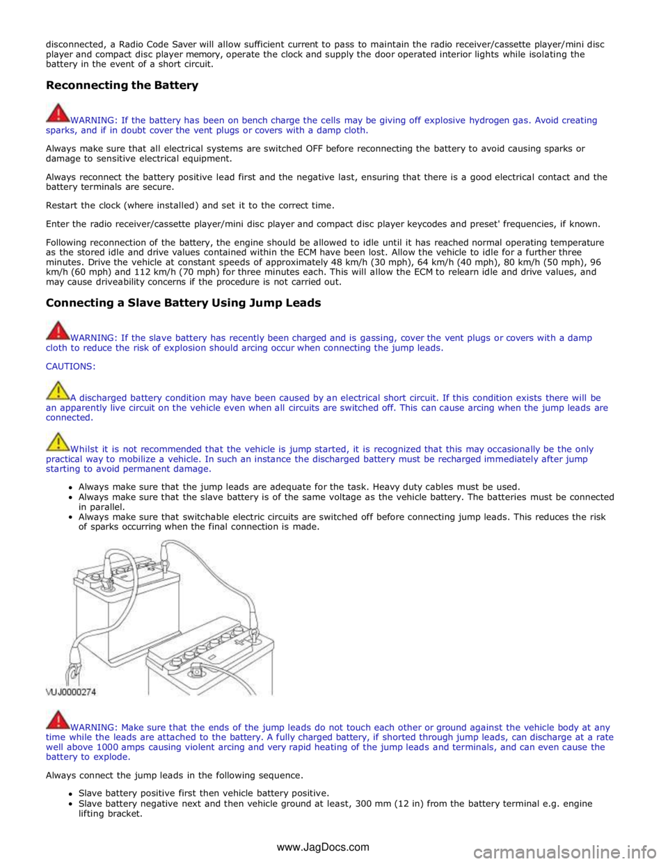
Always make sure that the jump leads are adequate for the task. Heavy duty cables must be used.
Always make sure that the slave battery is of the same voltage as the vehicle battery. The batteries must be connected
in parallel.
Always make sure that switchable electric circuits are switched off before connecting jump leads. This reduces the risk
of sparks occurring when the final connection is made.
WARNING: Make sure that the ends of the jump leads do not touch each other or ground against the vehicle body at any
time while the leads are attached to the battery. A fully charged battery, if shorted through jump leads, can discharge at a rate
well above 1000 amps causing violent arcing and very rapid heating of the jump leads and terminals, and can even cause the
battery to explode.
Always connect the jump leads in the following sequence.
Slave battery positive first then vehicle battery positive.
Slave battery negative next and then vehicle ground at least, 300 mm (12 in) from the battery terminal e.g. engine
lifting bracket. www.JagDocs.com
Page 79 of 3039

1 - Minor component movement clockwise/counterclockwise 2 - Major component movement clockwise/counterclockwise 3 - Component movement to the left/right/up/down 4 - Component movement towards/away 5 - 3 dimensional component movement 6 - 2 dimensional component movement 7
3 dimensional component rotation 8
3 dimensional component cycling
Page 80 of 3039
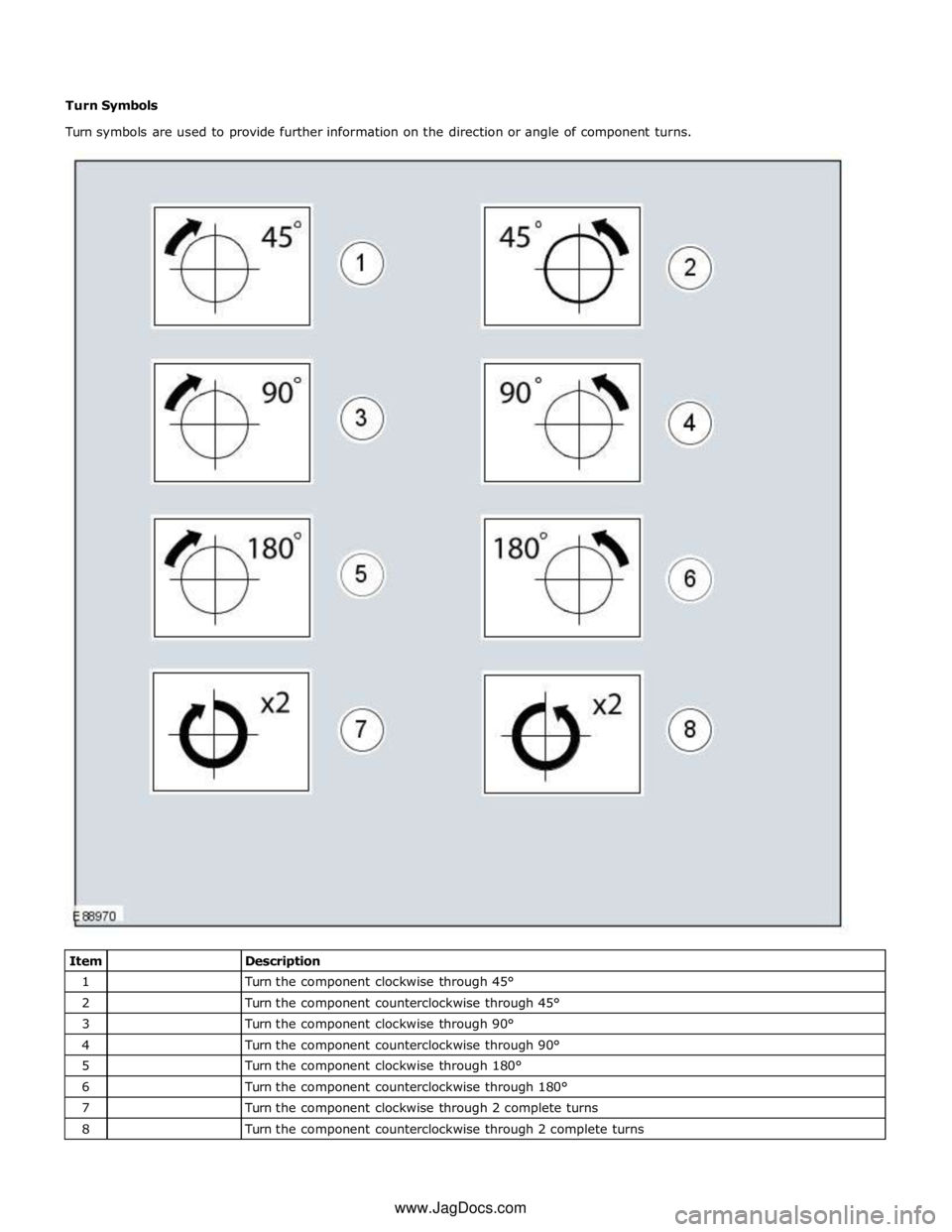
1
Turn the component clockwise through 45° 2
Turn the component counterclockwise through 45° 3
Turn the component clockwise through 90° 4
Turn the component counterclockwise through 90° 5
Turn the component clockwise through 180° 6
Turn the component counterclockwise through 180° 7
Turn the component clockwise through 2 complete turns 8
Turn the component counterclockwise through 2 complete turns www.JagDocs.com
Page 191 of 3039

DTC Description Possible Causes Action B10A0-11
Wiper/ Washer Switch -
Circuit short to ground
Wash/wipe circuit - short to
ground
Refer to the electrical circuit diagrams and check
wash/wipe circuit for short to ground B10A0-15
Wiper/ Washer Switch -
Circuit short to battery
or open
Wash/wipe circuit - short to
power, open circuit
Carry out any pinpoint tests associated with this
DTC using the manufacturer approved diagnostic
system. Refer to the electrical circuit diagrams
and check wash/wipe circuit for short to power,
open circuit B10A6-11
Main Light Switch -
Circuit short to ground
Master lighting switch circuit
- short to ground
Refer to the electrical circuit diagrams and check
master lighting switch circuit for short to ground B10A6-15
Main Light Switch -
Circuit short to battery
or open
Master lighting switch circuit
- short to power, open
circuit
Carry out any pinpoint tests associated with this
DTC using the manufacturer approved diagnostic
system. Refer to the electrical circuit diagrams
and check master lighting switch circuit for short
to power, open circuit B112B-87
Steering Wheel Module -
Missing message
Steering wheel module
failure - slave node not
responding
Carry out any pinpoint tests associated with this
DTC using the manufacturer approved diagnostic
system. Refer to the electrical circuit diagrams
and check the clockspring LIN circuit for short,
open circuit. Suspect the clockspring, check and
install a new clockspring as required, refer to the
new module/component installation note at the
top of the DTC Index B115C-7A Transfer Fuel Pump -
Fluid leak or seal failure
Fuel pump system fault
Check for fuel system jet pump or jet pump fuel
level sensor fault B1A85-15
Ambient Light Sensor -
Circuit short to battery
or open
Autolamp sensor circuit -
short to power, open circuit
Carry out any pinpoint tests associated with this
DTC using the manufacturer approved diagnostic
system. Refer to the electrical circuit diagrams
and check autolamp sensor circuit for short to
power, open circuit B1B01-00
Key Transponder - No
sub type information
Operator only cycles one key
During transponder key
programming the instrument
cluster, smartcard docking
station or key loses
power/circuit failure
Faulty key during key
programming
Unable to program
transponder key due to
noise/EMC related error
Ensure all keys to be programmed are available.
Refer to electrical circuit diagrams and check
power and ground supply circuits to all relevant
modules. Replace faulty key and repeat key
programming. Check CAN network for
interference/EMC related issues B1B01-05
Key Transponder -
System programming
failures
Error following SCU
replacement
Smartcard docking station
power and ground supply
circuits - short, open circuit
LIN fault
Instrument cluster power
and ground supply circuits -
short, open circuit
Carry out any pinpoint tests associated with this
DTC using the manufacturer approved diagnostic
system. Perform the Immobilisation application
from the Set-up menu using the manufacturer
approved diagnostic system. Refer to the
electrical circuit diagrams and check smartcard
docking station power and ground supply circuits
for short, open circuit and instrument cluster
power and ground supply circuits for short, open
circuit. Check LIN communications between
smartcard docking station and instrument cluster B1B01-51
Key Transponder - Not
programmed
LIN fault
Instrument cluster power
and ground supply circuits -
short, open circuit
Key fault
Smartcard docking station
power and ground supply
circuits - short, open circuit
Attempted to program a non
Carry out any pinpoint tests associated with this
DTC using the manufacturer approved diagnostic
system. Check LIN communications between
smartcard docking station and instrument
cluster. Refer to the electrical circuit diagrams
and check smartcard docking station power and
ground supply circuits for short, open circuit and
instrument cluster power and ground supply
circuits for short, open circuit. Confirm www.JagDocs.com
Page 307 of 3039
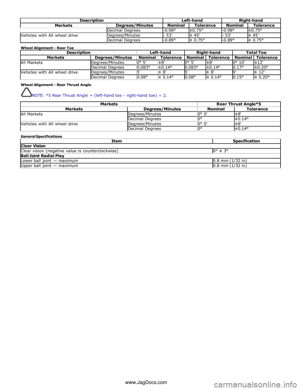
Description Left-hand Right-hand Markets Degrees/Minutes Nominal Tolerance Nominal Tolerance Decimal Degrees -0.98° ±0.75° -0.98° ±0.75° Vehicles with All wheel drive Degrees/Minutes - 53' ± 45' - 53' ± 45' Decimal Degrees -0.89° ± 0.75° -0.89° ± 0.75° Wheel Alignment - Rear Toe
Description Left-hand Right-hand Total Toe Markets Degrees/Minutes Nominal Tolerance Nominal Tolerance Nominal Tolerance All Markets Degrees/Minutes 0° 5' ±8' 0° 5' ±8' 0° 10' ±12' Decimal Degrees 0.083° ±0.14° 0.083° ±0.14° 0.17° ±0.20° Vehicles with All wheel drive Degrees/Minutes 5' ± 8' 5' ± 8' 9' ± 12' Decimal Degrees 0.08° ± 0.14° 0.08° ± 0.14° 0.15° ± 0.20° Wheel Alignment - Rear Thrust Angle
NOTE: *5 Rear Thrust Angle = (left-hand toe - right-hand toe) ÷ 2.
Markets Rear Thrust Angle*5 Markets Degrees/Minutes Nominal Tolerance All Markets Degrees/Minutes 0° 0' ±8' Decimal Degrees 0° ±0.14° Vehicles with All wheel drive Degrees/Minutes 0° 0' ±8' Decimal Degrees 0° ±0.14° General Specifications
Item Specification Clear Vision Clear vision (negative value is counterclockwise) 0° ± 3° Ball Joint Radial Play Lower ball joint — maximum 0.8 mm (1/32 in) Upper ball joint — maximum 0.8 mm (1/32 in) www.JagDocs.com
Page 440 of 3039
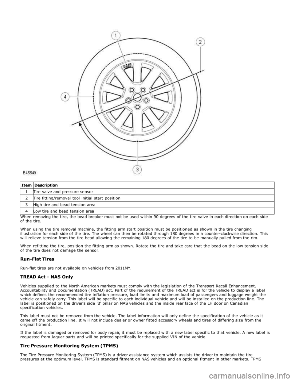
1 Tire valve and pressure sensor 2 Tire fitting/removal tool initial start position 3 High tire and bead tension area 4 Low tire and bead tension area When removing the tire, the bead breaker must not be used within 90 degrees of the tire valve in each direction on each side
of the tire.
When using the tire removal machine, the fitting arm start position must be positioned as shown in the tire changing
illustration for each side of the tire. The wheel can then be rotated through 180 degrees in a counter-clockwise direction. This
will relieve tension from the tire bead allowing the remaining 180 degrees of the tire to be manually pulled from the rim.
When refitting the tire, position the fitting arm as shown. Rotate the tire and take care that the bead on the low tension side
of the tire does not damage the sensor.
Run-Flat Tires
Run-flat tires are not available on vehicles from 2011MY.
TREAD Act - NAS Only
Vehicles supplied to the North American markets must comply with the legislation of the Transport Recall Enhancement,
Accountability and Documentation (TREAD) act. Part of the requirement of the TREAD act is for the vehicle to display a label
which defines the recommended tire inflation pressure, load limits and maximum load of passengers and luggage weight the
vehicle can safely carry. This label will be specific to each individual vehicle and will be installed on the production line. The
label is positioned on the driver's side 'B' pillar on NAS vehicles and the inside rear face of the LH door on Canadian
specification vehicles.
This label must not be removed from the vehicle. The label information will only define the specification of the vehicle as it
came off the production line. It will not include dealer or owner fitted accessory wheels and tires of differing size from the
original fitment.
If the label is damaged or removed for body repair, it must be replaced with a new label specific to that vehicle. A new label is
requested from Jaguar parts and will be printed specifically for the supplied VIN of the vehicle.
Tire Pressure Monitoring System (TPMS)
The Tire Pressure Monitoring System (TPMS) is a driver assistance system which assists the driver to maintain the tire
pressures at the optimum level. TPMS is standard fitment on NAS vehicles and an optional fitment in other markets. TPMS
Page 715 of 3039
Published: 11-May-2011
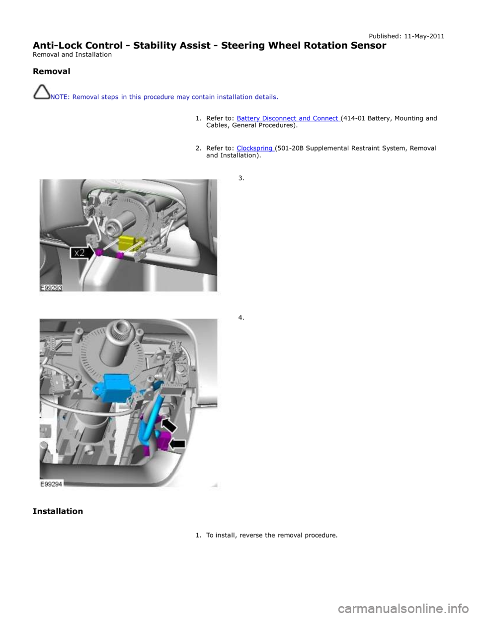
Anti-Lock Control - Stability Assist - Steering Wheel Rotation Sensor
Removal and Installation
Removal
NOTE: Removal steps in this procedure may contain installation details.
1. Refer to: Battery Disconnect and Connect (414-01 Battery, Mounting and Cables, General Procedures).
2. Refer to: Clockspring (501-20B Supplemental Restraint System, Removal and Installation).
3.
4.
Installation
1. To install, reverse the removal procedure.
Page 722 of 3039
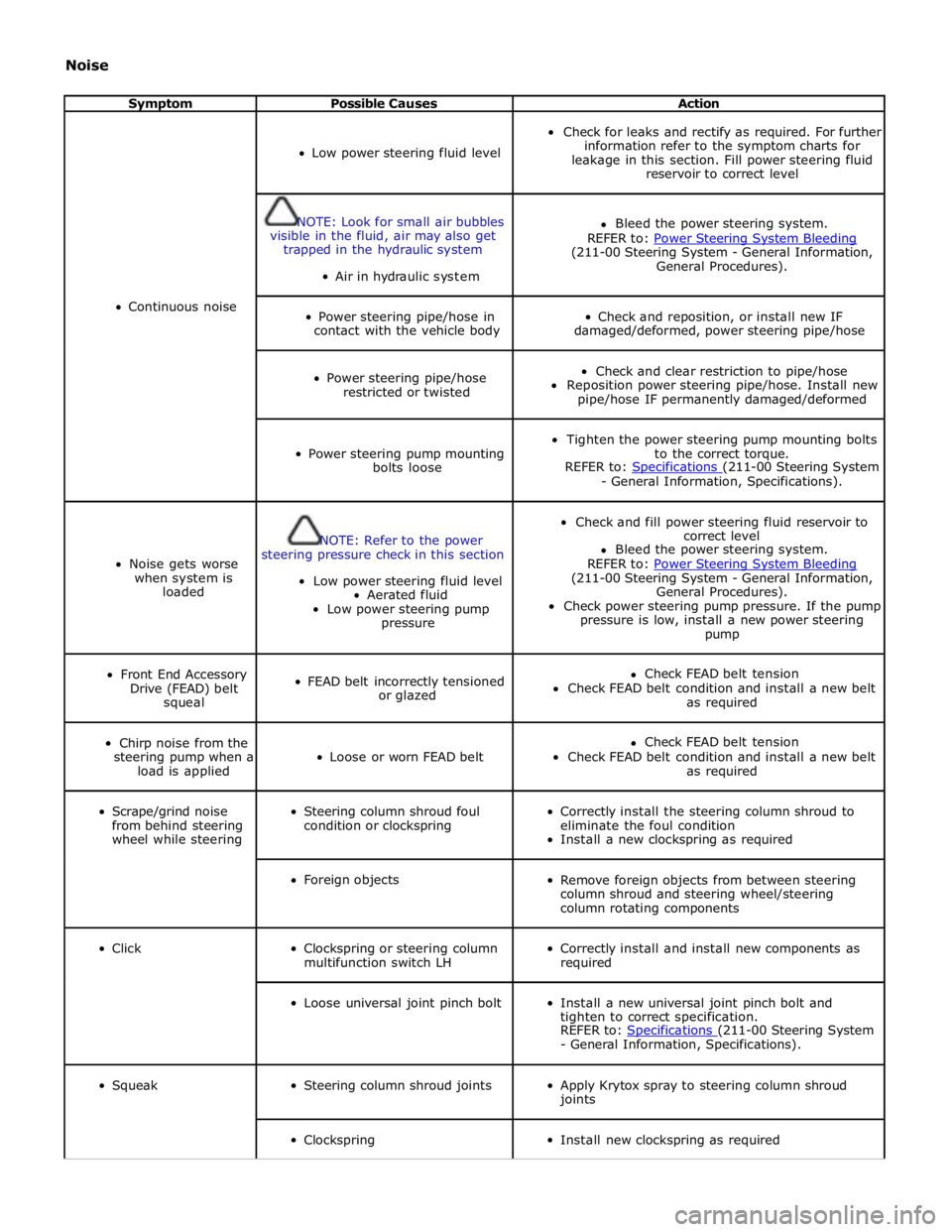
Noise
Symptom Possible Causes Action
Continuous noise
Low power steering fluid level
Check for leaks and rectify as required. For further
information refer to the symptom charts for
leakage in this section. Fill power steering fluid
reservoir to correct level
NOTE: Look for small air bubbles
visible in the fluid, air may also get
trapped in the hydraulic system
Air in hydraulic system
Bleed the power steering system.
REFER to: Power Steering System Bleeding (211-00 Steering System - General Information,
General Procedures).
Power steering pipe/hose in
contact with the vehicle body
Check and reposition, or install new IF
damaged/deformed, power steering pipe/hose
Power steering pipe/hose
restricted or twisted
Check and clear restriction to pipe/hose
Reposition power steering pipe/hose. Install new
pipe/hose IF permanently damaged/deformed
Power steering pump mounting
bolts loose
Tighten the power steering pump mounting bolts
to the correct torque.
REFER to: Specifications (211-00 Steering System - General Information, Specifications).
Noise gets worse
when system is
loaded
NOTE: Refer to the power
steering pressure check in this section
Low power steering fluid level
Aerated fluid
Low power steering pump
pressure
Check and fill power steering fluid reservoir to
correct level
Bleed the power steering system.
REFER to: Power Steering System Bleeding (211-00 Steering System - General Information,
General Procedures).
Check power steering pump pressure. If the pump
pressure is low, install a new power steering
pump
Front End Accessory
Drive (FEAD) belt
squeal
FEAD belt incorrectly tensioned
or glazed
Check FEAD belt tension
Check FEAD belt condition and install a new belt
as required
Chirp noise from the
steering pump when a
load is applied
Loose or worn FEAD belt
Check FEAD belt tension
Check FEAD belt condition and install a new belt
as required
Scrape/grind noise
from behind steering
wheel while steering
Steering column shroud foul
condition or clockspring
Correctly install the steering column shroud to
eliminate the foul condition
Install a new clockspring as required
Foreign objects
Remove foreign objects from between steering
column shroud and steering wheel/steering
column rotating components
Click
Clockspring or steering column
multifunction switch LH
Correctly install and install new components as
required
Loose universal joint pinch bolt
Install a new universal joint pinch bolt and
tighten to correct specification.
REFER to: Specifications (211-00 Steering System - General Information, Specifications).
Squeak
Steering column shroud joints
Apply Krytox spray to steering column shroud
joints
Clockspring
Install new clockspring as required
Page 744 of 3039

1 Return fluid control groove 2 Radial groove 3 Feed fluid control groove 4 Radial groove 5 Axial groove 6 Feed fluid control edge 7 Feed fluid radial groove 8 Return fluid control edge 9 Return fluid chamber 10 Cut-off valve 11 Radial groove 12 Servotronic transducer valve 13 Feed fluid radial groove 14 Radial groove 15 Orifice 16 Balls 17 Compression spring 18 Torsion bar 19 Power steering fluid reservoir 20 Valve rotor 21 Reaction piston 22 Reaction chamber 23 Centering piece 24 Pressure relief/flow limiting valve 25 Power steering pump 26 Inner tie-rod 27 Pinion 28 Valve sleeve 29 Steering gear rack 30 Steering gear housing 31 Power assist cylinder - right 32 Piston 33 Power assist cylinder - left When the steering wheel is turned to the right, the steering rack and piston moves to the left in the piston bore. The valve
rotor is rotated to the right (clockwise) and pressurized fluid is directed over the further opened feed fluid control edges and to
the associated axial grooves, the radial groove and via an external pipe to the left power assist cylinder chamber. The pressure
applied to the piston from the left power assist cylinder chamber provides the hydraulic assistance.
An adaptable pressure build-up is achieved by the partially or fully closed feed fluid control edges restricting or preventing a
connection between the fluid pressure inlet and the other axial grooves connected to the radial groove.
Simultaneously, the fluid pressure outlet to the pressurized axial grooves are restricted or partially restricted by the closing
return fluid control edges. The fluid displaced by the piston from the right power assist cylinder chamber, flows through an
external pipe to the radial grooves. From there the fluid passes to the associated axial grooves and on to the return fluid
control grooves, via the further opened return fluid control edges.
The return flow of fluid to the reservoir passes via interconnecting bores which lead to the return fluid chamber. When the
steering wheel is turned to the left the operating sequence is as above but the pressure is applied to the opposite side of the
piston.
Servotronic Operation
The Servotronic software contains a number of steering maps which are selected via the car configuration file depending on the
vehicle mode and tire fitment.
If a failure of the Servotronic valve or software occurs, the system will suspend Servotronic assistance and only normal power
steering wheel be available. Fault codes relating to the fault are stored, but no warning lamps are illuminated and the driver
may be aware of the steering being 'heavier' than usual.
When the vehicle is manoeuvred into and out of a parking space (or other similar manoeuvre), the Servotronic software uses
road speed data from the ABS module to determine the vehicle speed, which in this case will be slow or stationary. The
Servotronic software analyses the signals and outputs an appropriate control current to the Servotronic transducer valve. The
Servotronic valve closes and prevents fluid flowing from the feed fluid radial groove to the reaction chamber. An orifice also