headlamp JAGUAR XFR 2010 1.G User Guide
[x] Cancel search | Manufacturer: JAGUAR, Model Year: 2010, Model line: XFR, Model: JAGUAR XFR 2010 1.GPages: 3039, PDF Size: 58.49 MB
Page 799 of 3039
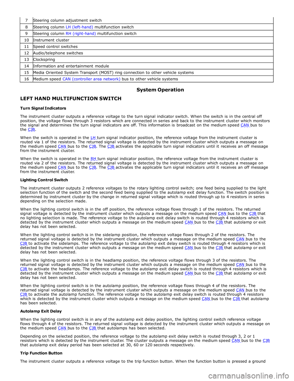
8 Steering column LH (left-hand) multifunction switch 9 Steering column RH (right-hand) multifunction switch 10 Instrument cluster 11 Speed control switches 12 Audio/telephone switches 13 Clockspring 14 Information and entertainment module 15 Media Oriented System Transport (MOST) ring connection to other vehicle systems 16 Medium speed CAN (controller area network) bus to other vehicle systems
LEFT HAND MULTIFUNCTION SWITCH
Turn Signal Indicators System Operation
The instrument cluster outputs a reference voltage to the turn signal indicator switch. When the switch is in the central off
position, the voltage flows through 3 resistors which are connected in series and back to the instrument cluster which monitors
the signal and determines the turn signal indicators are off. This information is broadcast on the medium speed CAN bus to the CJB.
When the switch is operated in the LH turn signal indicator position, the reference voltage from the instrument cluster is routed via 1 of the resistors. The returned signal voltage is detected by the instrument cluster which outputs a message on
the medium speed CAN bus to the CJB. The CJB activates the applicable turn signal indicators until it receives an off message from the instrument cluster.
When the switch is operated in the RH turn signal indicator position, the reference voltage from the instrument cluster is routed via 2 of the resistors. The returned signal voltage is detected by the instrument cluster which outputs a message on
the medium speed CAN bus to the CJB. The CJB activates the applicable turn signal indicators until it receives an off message from the instrument cluster.
Lighting Control Switch
The instrument cluster outputs 2 reference voltages to the rotary lighting control switch; one feed being supplied to the light
selection function of the switch and the second feed being supplied to the autolamp exit delay function. The switch position is
determined by instrument cluster by the change in returned signal voltage which is routed through up to 4 resistors in series
depending on the selection made.
When the lighting control switch is in the off position, the reference voltage flows through 1 of the resistors. The returned
signal voltage is detected by the instrument cluster which outputs a message on the medium speed CAN bus to the CJB that no lighting selection is made. The reference voltage to the autolamp exit delay switch is routed through 4 resistors which is
detected by the instrument cluster which outputs a message on the medium speed CAN bus to the CJB that autolamp or exit delay has not been selected.
When the lighting control switch is in the sidelamp position, the reference voltage flows through 2 of the resistors. The
returned signal voltage is detected by the instrument cluster which outputs a message on the medium speed CAN bus to the CJB to activate the sidelamps. The reference voltage to the autolamp exit delay switch is routed through 4 resistors which is detected by the instrument cluster which outputs a message on the medium speed CAN bus to the CJB that autolamp or exit delay has not been selected.
When the lighting control switch is in the headlamp position, the reference voltage flows through 3 of the resistors. The
returned signal voltage is detected by the instrument cluster which outputs a message on the medium speed CAN bus to the CJB to activate the headlamps. The reference voltage to the autolamp exit delay switch is routed through 4 resistors which is detected by the instrument cluster which outputs a message on the medium speed CAN bus to the CJB that autolamp or exit delay has not been selected.
When the lighting control switch is in the autolamp position, the reference voltage flows through 4 of the resistors. The
returned signal voltage is detected by the instrument cluster which outputs a message on the medium speed CAN bus to the CJB to activate the autolamp function. The reference voltage to the autolamp exit delay switch is routed through 4 resistors which is detected by the instrument cluster which outputs a message on the medium speed CAN bus to the CJB that autolamp has been selected.
Autolamp Exit Delay
When the lighting control switch is in any of the autolamp exit delay position, the lighting control switch reference voltage
flows through 4 of the resistors. The returned signal voltage is detected by the instrument cluster which outputs a message on
the medium speed CAN bus to the CJB that autolamps has been selected.
Depending on the selected position, the reference voltage to the autolamp exit delay switch is routed through 3, 2 or 1
resistors which is detected by the instrument cluster. The cluster outputs a message on the medium speed CAN bus to the CJB that autolamp exit delay period has been selected at 30, 60 or 120 seconds respectively.
Trip Function Button
The instrument cluster outputs a reference voltage to the trip function button. When the function button is pressed a ground
Page 801 of 3039
battery power supply to be passed via the slip ring assembly in the steering wheel to the heated steering wheel control
module. The steering wheel module supplies power to the steering wheel heater element and also monitors the temperature
via a NTC (negative temperature coefficient) temperature sensor incorporated into the heater element. The control module
varies the power supply to the element to maintain the steering wheel rim at the optimum temperature.
Component Description STEERING COLUMN MULTIFUNCTION SWITCHES
The steering column multifunction switches are situated on the steering column and consists of the wiper switch, the turn
signal indicator/lighting switch and the trip computer switch.
The steering column adjustment switch is located in the steering column lower shroud on the LH side. The switch is a 4 position 'joystick' which controls reach and rake adjustment.
Steering wheel mounted switches on the LH side of the driver's airbag, control the audio and telephone functions. Switches on the RH side of the driver's airbag, control the speed control functions. For additional information, refer to:
Audio System (415-01A Information and Entertainment System, Description and Operation), Speed Control (310-03A, Description and Operation),
Speed Control (310-03B, Description and Operation),
Speed Control (310-03C, Description and Operation).
Two transmission paddle switches are located at the rear of the steering wheel.
Refer to: External Controls (307-05, Description and Operation).
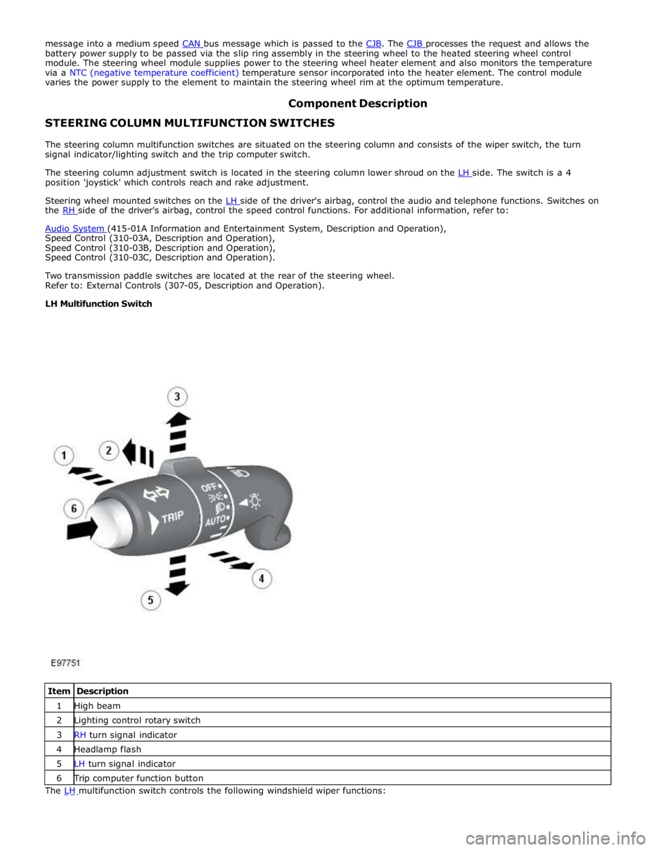
LH Multifunction Switch
Item Description 1 High beam 2 Lighting control rotary switch 3 RH turn signal indicator 4 Headlamp flash 5 LH turn signal indicator 6 Trip computer function button The LH multifunction switch controls the following windshield wiper functions:
Page 802 of 3039
Turn signal indicators
Side lamps
Headlamps
Auto lamps
High/low beam
Headlamp flash
Headlamp timer
Trip computer.
The switch is located in a slot in the clockspring and secured with 2 plastic clips.
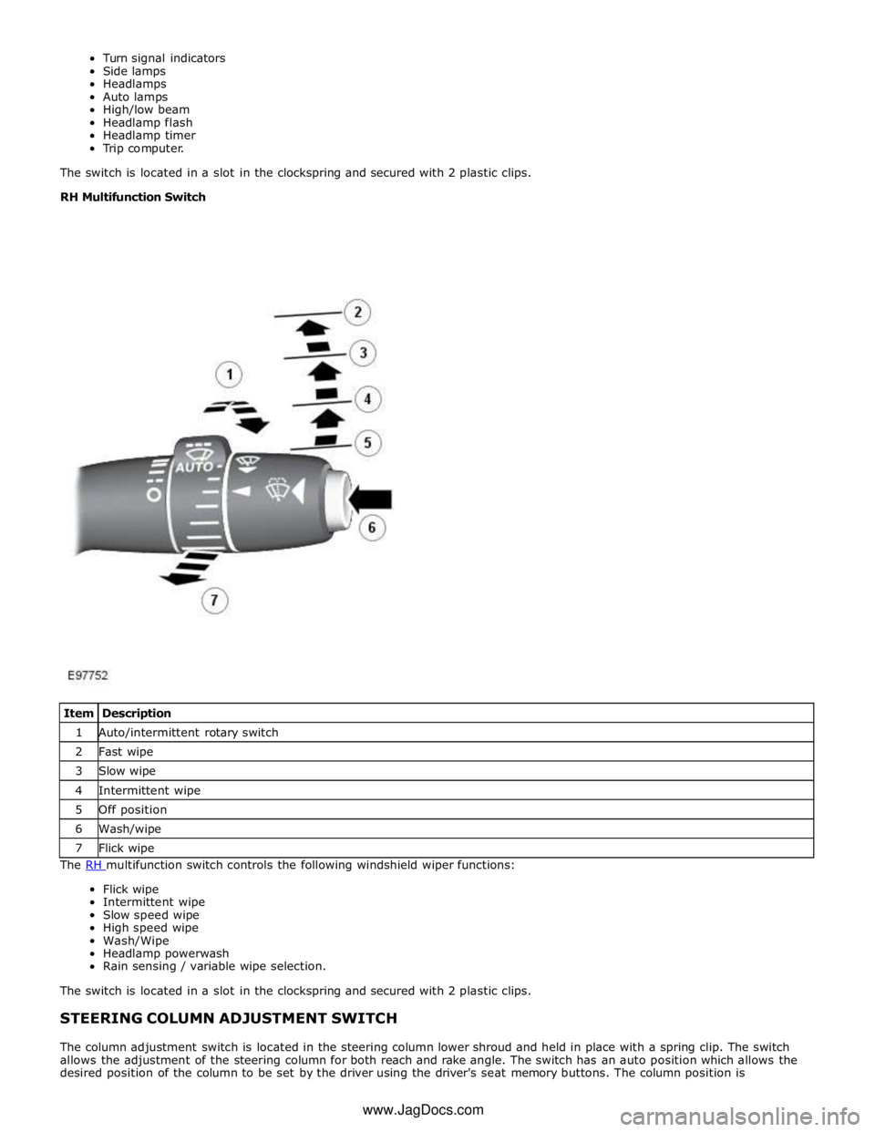
RH Multifunction Switch
The RH multifunction switch controls the following windshield wiper functions: Flick wipe
Intermittent wipe
Slow speed wipe
High speed wipe
Wash/Wipe
Headlamp powerwash
Rain sensing / variable wipe selection.
The switch is located in a slot in the clockspring and secured with 2 plastic clips.
STEERING COLUMN ADJUSTMENT SWITCH
The column adjustment switch is located in the steering column lower shroud and held in place with a spring clip. The switch
allows the adjustment of the steering column for both reach and rake angle. The switch has an auto position which allows the
desired position of the column to be set by the driver using the driver's seat memory buttons. The column position is Item Description 1 Auto/intermittent rotary switch 2 Fast wipe 3 Slow wipe 4 Intermittent wipe 5 Off position 6 Wash/wipe 7 Flick wipe www.JagDocs.com
Page 1787 of 3039
the RCM and illuminated by the instrument cluster on receipt of high speed CAN bus messages. The safety belt warning indicator is not subject to the 3 second indicator check when the ignition is switched on.
The operation of the passenger seat buckle switch is as described below with the exception that the instrument cluster must
receive a hardwired signal from the belt minder control module to indicate that a passenger is occupying the seat.
The safety belt warning indicator is subject to a timer. The warning indicator is activated when the following conditions exist:
Ignition is switched on
One of the front seat belts is unbuckled
USA market only - 75 seconds has elapsed after ignition on mode is selected
Vehicle is not in reverse gear
Vehicle speed is more than 8 km/h (5 mph).
Once the above parameters are met, the instrument cluster flashes the warning indicator at 2 Hz for 10 seconds accompanied
by a simultaneous chime. After 10 seconds the chime ceases and the warning indicator is permanently illuminated for 20
seconds. This sequence is repeated every 30 seconds until one of the following events occurs:
300 seconds has elapsed
The safety belt of the occupied front seats is fastened
The ignition is switched to off mode
The vehicle speed decreases to below 5 km/h (3 mph).
NOTE: On USA market vehicles, the warning indicator in not permanently illuminated.
The safety belt minder function cannot be disabled. The seat belt minder function can be disabled.
Refer to: Safety Belt System (501-20A Safety Belt System, Description and Operation). 14. Side Lamp Indicator
The instrument cluster controls the green colored side lamp indicator on receipt of a side lamp status message on the medium
speed CAN bus from the CJB and the auxiliary junction box. The lighting switch on the LH steering column multifunction switch is connected to the instrument cluster. Selections using this switch are detected by the cluster which requests the side or
headlamp operation via a message to the CJB and the RJB. The CJB and the RJB responds with a side lamp active message and the cluster illuminates the side lamp indicator. The side lamp indicator is not subject to the 3 second indicator check when
the ignition is switched on.
15. High Beam Indicator
The instrument cluster controls the blue colored high beam indicator on receipt of a high beam status message on the medium
speed CAN bus from the CJB. The lighting switch on the LH steering column multifunction switch is connected to the instrument cluster. High beam or flash selections using this switch are detected by the cluster which requests the light
operation via a CAN message to the CJB. The CJB responds with a high beam active message and the cluster illuminates the high beam indicator. The high beam indicator is not subject to the 3 second indicator check when the ignition is switched on.
16. Rear Fog Lamp Indicator
The amber colored rear fog lamp indicator is controlled by the auxiliary junction box and illuminated by the instrument cluster
on receipt of a rear fog lamp on message on the medium speed CAN bus from the RJB. The indicator is illuminated for as long as the rear fog lamps are active. The rear fog lamp indicator is not subject to the 3 second indicator check when the ignition is
switched on.
SPEEDOMETER
The speedometer is driven by high speed CAN signals transmitted by the ABS module. The wheel speeds are measured by sensors reading the rotational speed of the rear wheels from toothed targets on the hubs. An average of the two wheel speeds
are passed from the sensors to the ABS module in the form of pulsed signals. The ABS module converts these signals into a speed output on the high speed CAN to the instrument cluster. The same speed outputs from the wheel speed sensors are also used to calculate the distance the vehicle has travelled.
TACHOMETER
The tachometer is driven by an engine speed signal transmitted on the high speed CAN from the ECM. The signal is derived from the CKP (crankshaft position) sensor. The signal is received by the instrument cluster microprocessor and the output from
the microprocessor drives the tachometer.
FUEL GAGE
The fuel gage is controlled by CAN messages from the RJB. The RJB reads the values output by the fuel level sensors every 131 ms and transmits a fuel tank contents value, corrected for battery voltage, in a CAN message to the instrument cluster. A fuel pump symbol is displayed to the left of the linear gage. An arrow above the symbol shows the driver on which side of the
vehicle the fuel filler cap is located. Above the linear fuel gage, is a LCD (liquid crystal display) area which displays odometer
and trip readouts. When a trip computer function is selected, these are replaced by a trip computer display for the trip function
selected.
LIQUID CRYSTAL DISPLAY
In the area above and below the message center is a LCD display. The area below the message center displays a linear fuel www.JagDocs.com
Page 1805 of 3039

DTC Description Possible Cause Action U013900
Lost
Communication
with Suspension
Control Module 'B'
Loss of CAN communication
with adaptive damping module Carry out any pinpoint tests associated with this DTC using
the manufacturer approved diagnostic system. Check
adaptive damping module for DTCs and refer to the relevant
DTC Index U014000
Lost
Communication
With Body
Control Module
Loss of CAN communication
with CJB Carry out any pinpoint tests associated with this DTC using
the manufacturer approved diagnostic system. Check CJB for
DTCs and refer to the relevant DTC Index U014200
Lost
Communication
With Body
Control Module
"B"
Loss of CAN communication
with RJB Carry out any pinpoint tests associated with this DTC using
the manufacturer approved diagnostic system. Check RJB for
DTCs and refer to the relevant DTC Index U015100
Lost
Communication
With Restraints
Control Module
Loss of CAN communication
with RCM Carry out any pinpoint tests associated with this DTC using
the manufacturer approved diagnostic system. Check RCM for
DTCs and refer to the relevant DTC Index U015600
Lost
Communication
with Information
Centre 'A'
Loss of CAN communication
with information and
entertainment control module Carry out any pinpoint tests associated with this DTC using
the manufacturer approved diagnostic system. Check
information and entertainment control module for DTCs and
refer to the relevant DTC Index U016400
Lost
Communication
with HVAC
Control Module
Loss of CAN communication
with climate control module Carry out any pinpoint tests associated with this DTC using
the manufacturer approved diagnostic system. Check climate
control module for DTCs and refer to the relevant DTC Index U019900
Lost
Communication
with Door Control
Module 'A'
Loss of CAN communication
with driver door module (DDM) Carry out any pinpoint tests associated with this DTC using
the manufacturer approved diagnostic system. Check DDM for
DTCs and refer to the relevant DTC Index U020000
Lost
Communication
with Door Control
Module 'B'
Loss of CAN communication
with passenger door module
(PDM) Carry out any pinpoint tests associated with this DTC using
the manufacturer approved diagnostic system. Check PDM for
DTCs and refer to the relevant DTC Index U020800
Lost
Communication
with Seat Control
Module 'A'
Loss of CAN communication
with driver seat module (DSM) Carry out any pinpoint tests associated with this DTC using
the manufacturer approved diagnostic system. Check DSM for
DTCs and refer to the relevant DTC Index U021400
Lost
Communication
with Remote
Function
Actuation
Loss of CAN communication
with keyless vehicle module
(KVM) Carry out any pinpoint tests associated with this DTC using
the manufacturer approved diagnostic system. Check KVM for
DTCs and refer to the relevant DTC Index U024100
Lost
Communication
with Headlamp
Control Module 'A'
Loss of CAN communication
with headlamp control module Carry out any pinpoint tests associated with this DTC using
the manufacturer approved diagnostic system. Check
headlamp control module for DTCs and refer to the relevant
DTC Index U025000
Lost
Communication
with Impact
Classification System Module
Loss of CAN communication
with pedestrian protection
module Carry out any pinpoint tests associated with this DTC using
the manufacturer approved diagnostic system. Check
pedestrian protection module for DTCs and refer to the
relevant DTC Index U025600
Lost
Communication
with Front
Controls Interface
Module 'A'
Loss of CAN communication
with integrated control panel Carry out any pinpoint tests associated with this DTC using
the manufacturer approved diagnostic system. Check
integrated control panel for DTCs and refer to the relevant
DTC Index U030000
Internal Control
Module Software
Incompatibility
Invalid configuration message
is received Re-configure the RJB using the manufacturer approved
diagnostic system. Clear the DTC and retest. If the DTC is
still logged suspect the instrument cluster, refer to the new
module/component installation note at the top of the DTC
Index U040268
Invalid data
received from
TCM
Algorithm based failures -
events information Check TCM for DTCs and refer to the relevant DTC Index U200411
Auxiliary Switch
Pack
Auxiliary switch signal circuit -
short to ground Refer to the electrical circuit diagrams and check auxiliary
switch signal circuit for short to ground U200415
Auxiliary Switch
Pack
Auxiliary switch signal circuit -
short to power, open circuit Carry out any pinpoint tests associated with this DTC using
the manufacturer approved diagnostic system. Refer to the
electrical circuit diagrams and check auxiliary switch signal
circuit for short to power, open circuit
Page 1828 of 3039
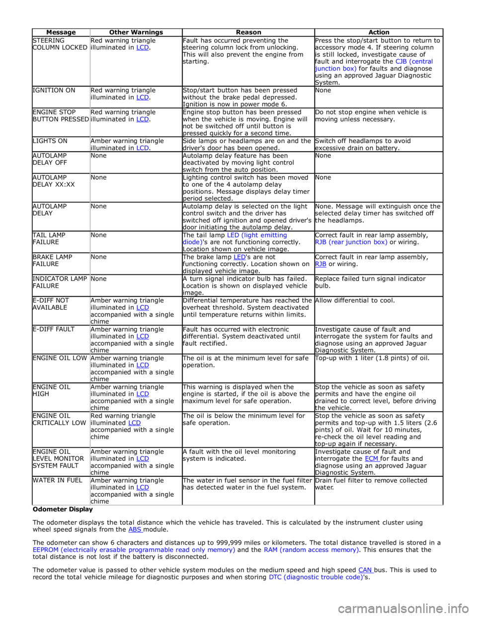
STEERING
COLUMN LOCKED Red warning triangle
illuminated in LCD. Fault has occurred preventing the
steering column lock from unlocking. This will also prevent the engine from
starting. Press the stop/start button to return to
accessory mode 4. If steering column
is still locked, investigate cause of
fault and interrogate the CJB (central junction box) for faults and diagnose
using an approved Jaguar Diagnostic System. IGNITION ON
Red warning triangle
illuminated in LCD. Stop/start button has been pressed
without the brake pedal depressed. Ignition is now in power mode 6. None ENGINE STOP
BUTTON PRESSED Red warning triangle
illuminated in LCD. Engine stop button has been pressed
when the vehicle is moving. Engine will
not be switched off until button is pressed quickly for a second time. Do not stop engine when vehicle is
moving unless necessary. LIGHTS ON
Amber warning triangle
illuminated in LCD. Side lamps or headlamps are on and the
driver's door has been opened. Switch off headlamps to avoid
excessive drain on battery. AUTOLAMP
DELAY OFF None
Autolamp delay feature has been
deactivated by moving light control
switch from the auto position. None AUTOLAMP
DELAY XX:XX None
Lighting control switch has been moved
to one of the 4 autolamp delay
positions. Message displays delay timer period selected. None AUTOLAMP
DELAY None
Autolamp delay is selected on the light
control switch and the driver has
switched off ignition and opened driver's
door initiating the autolamp delay. None. Message will extinguish once the
selected delay timer has switched off
the headlamps. TAIL LAMP
FAILURE None The tail lamp LED (light emitting
diode)'s are not functioning correctly.
Location shown on vehicle image. Correct fault in rear lamp assembly,
RJB (rear junction box) or wiring. BRAKE LAMP
FAILURE None The brake lamp LED's are not functioning correctly. Location shown on displayed vehicle image. Correct fault in rear lamp assembly,
RJB or wiring. INDICATOR LAMP
FAILURE None
A turn signal indicator bulb has failed.
Location is shown on displayed vehicle image. Replace failed turn signal indicator
bulb. E-DIFF NOT
AVAILABLE Amber warning triangle
illuminated in LCD accompanied with a single
chime Differential temperature has reached the
overheat threshold. System deactivated
until temperature returns within limits. Allow differential to cool. E-DIFF FAULT
Amber warning triangle
illuminated in LCD accompanied with a single
chime Fault has occurred with electronic
differential. System deactivated until
fault rectified. Investigate cause of fault and
interrogate the system for faults and
diagnose using an approved Jaguar Diagnostic System. ENGINE OIL LOW
Amber warning triangle
illuminated in LCD accompanied with a single
chime The oil is at the minimum level for safe
operation. Top-up with 1 liter (1.8 pints) of oil. ENGINE OIL
HIGH Amber warning triangle
illuminated in LCD accompanied with a single
chime This warning is displayed when the
engine is started, if the oil is above the
maximum level for safe operation. Stop the vehicle as soon as safety
permits and have the engine oil
drained to correct level, before driving
the vehicle. ENGINE OIL
CRITICALLY LOW Red warning triangle
illuminated LCD accompanied with a single
chime The oil is below the minimum level for
safe operation. Stop the vehicle as soon as safety
permits and top-up with 1.5 liters (2.6
pints) of oil. Wait for 10 minutes,
re-check the oil level reading and top-up again if necessary. ENGINE OIL
LEVEL MONITOR
SYSTEM FAULT Amber warning triangle
illuminated in LCD accompanied with a single
chime A fault with the oil level monitoring
system is indicated. Investigate cause of fault and
interrogate the ECM for faults and diagnose using an approved Jaguar Diagnostic System. WATER IN FUEL
Amber warning triangle
illuminated in LCD accompanied with a single
chime The water in fuel sensor in the fuel filter
has detected water in the fuel system. Drain fuel filter to remove collected
water. Odometer Display
The odometer displays the total distance which the vehicle has traveled. This is calculated by the instrument cluster using
wheel speed signals from the ABS module.
The odometer can show 6 characters and distances up to 999,999 miles or kilometers. The total distance travelled is stored in a
EEPROM (electrically erasable programmable read only memory) and the RAM (random access memory). This ensures that the
total distance is not lost if the battery is disconnected.
The odometer value is passed to other vehicle system modules on the medium speed and high speed CAN bus. This is used to record the total vehicle mileage for diagnostic purposes and when storing DTC (diagnostic trouble code)'s.
Page 1868 of 3039
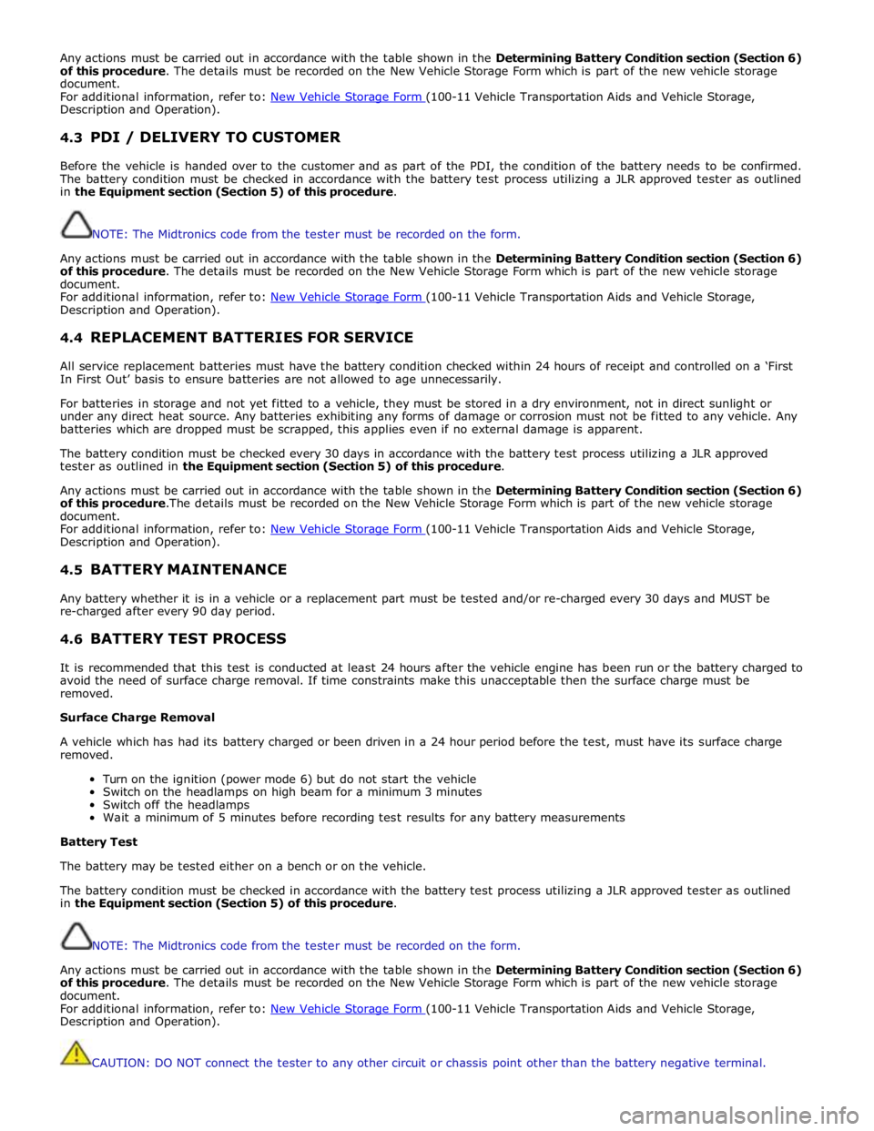
Any actions must be carried out in accordance with the table shown in the Determining Battery Condition section (Section 6)
of this procedure. The details must be recorded on the New Vehicle Storage Form which is part of the new vehicle storage
document.
For additional information, refer to: New Vehicle Storage Form (100-11 Vehicle Transportation Aids and Vehicle Storage, Description and Operation).
4.3 PDI / DELIVERY TO CUSTOMER
Before the vehicle is handed over to the customer and as part of the PDI, the condition of the battery needs to be confirmed.
The battery condition must be checked in accordance with the battery test process utilizing a JLR approved tester as outlined
in the Equipment section (Section 5) of this procedure.
NOTE: The Midtronics code from the tester must be recorded on the form.
Any actions must be carried out in accordance with the table shown in the Determining Battery Condition section (Section 6)
of this procedure. The details must be recorded on the New Vehicle Storage Form which is part of the new vehicle storage
document.
For additional information, refer to: New Vehicle Storage Form (100-11 Vehicle Transportation Aids and Vehicle Storage, Description and Operation).
4.4 REPLACEMENT BATTERIES FOR SERVICE
All service replacement batteries must have the battery condition checked within 24 hours of receipt and controlled on a ‘First
In First Out’ basis to ensure batteries are not allowed to age unnecessarily.
For batteries in storage and not yet fitted to a vehicle, they must be stored in a dry environment, not in direct sunlight or
under any direct heat source. Any batteries exhibiting any forms of damage or corrosion must not be fitted to any vehicle. Any
batteries which are dropped must be scrapped, this applies even if no external damage is apparent.
The battery condition must be checked every 30 days in accordance with the battery test process utilizing a JLR approved
tester as outlined in the Equipment section (Section 5) of this procedure.
Any actions must be carried out in accordance with the table shown in the Determining Battery Condition section (Section 6)
of this procedure.The details must be recorded on the New Vehicle Storage Form which is part of the new vehicle storage
document.
For additional information, refer to: New Vehicle Storage Form (100-11 Vehicle Transportation Aids and Vehicle Storage, Description and Operation).
4.5 BATTERY MAINTENANCE
Any battery whether it is in a vehicle or a replacement part must be tested and/or re-charged every 30 days and MUST be
re-charged after every 90 day period.
4.6 BATTERY TEST PROCESS
It is recommended that this test is conducted at least 24 hours after the vehicle engine has been run or the battery charged to
avoid the need of surface charge removal. If time constraints make this unacceptable then the surface charge must be
removed.
Surface Charge Removal
A vehicle which has had its battery charged or been driven in a 24 hour period before the test, must have its surface charge
removed.
Turn on the ignition (power mode 6) but do not start the vehicle
Switch on the headlamps on high beam for a minimum 3 minutes
Switch off the headlamps
Wait a minimum of 5 minutes before recording test results for any battery measurements
Battery Test
The battery may be tested either on a bench or on the vehicle.
The battery condition must be checked in accordance with the battery test process utilizing a JLR approved tester as outlined
in the Equipment section (Section 5) of this procedure.
NOTE: The Midtronics code from the tester must be recorded on the form.
Any actions must be carried out in accordance with the table shown in the Determining Battery Condition section (Section 6)
of this procedure. The details must be recorded on the New Vehicle Storage Form which is part of the new vehicle storage
document.
For additional information, refer to: New Vehicle Storage Form (100-11 Vehicle Transportation Aids and Vehicle Storage, Description and Operation).
CAUTION: DO NOT connect the tester to any other circuit or chassis point other than the battery negative terminal.
Page 1890 of 3039
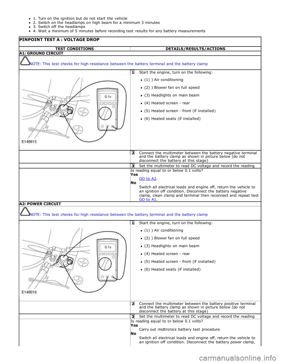
1. Turn on the ignition but do not start the vehicle
2. Switch on the headlamps on high beam for a minimum 3 minutes
3. Switch off the headlamps
4. Wait a minimum of 5 minutes before recording test results for any battery measurements
PINPOINT TEST A : VOLTAGE DROP TEST CONDITIONS DETAILS/RESULTS/ACTIONS A1: GROUND CIRCUIT
NOTE: This test checks for high resistance between the battery terminal and the battery clamp 1 Start the engine, turn on the following: (1) ) Air conditioning
(2) ) Blower fan on full speed
(3) Headlights on main beam
(4) Heated screen - rear
(5) Heated screen - front (if installed)
(6) Heated seats (if installed) 2 Connect the multimeter between the battery negative terminal and the battery clamp as shown in picture below (do not
disconnect the battery at this stage) 3 Set the multimeter to read DC voltage and record the reading Is reading equal to or below 0.1 volts? Yes
GO to A2. No
Switch all electrical loads and engine off, return the vehicle to
an ignition off condition. Disconnect the battery negative
clamp, clean clamp and terminal then reconnect and repeat test
GO to A1. A2: POWER CIRCUIT
NOTE: This test checks for high resistance between the battery terminal and the battery clamp 1 Start the engine, turn on the following: (1) ) Air conditioning
(2) ) Blower fan on full speed
(3) Headlights on main beam
(4) Heated screen - rear
(5) Heated screen - front (if installed)
(6) Heated seats (if installed) 2 Connect the multimeter between the battery positive terminal and the battery clamp as shown in picture below (do not
disconnect the battery at this stage) 3 Set the multimeter to read DC voltage and record the reading Is reading equal to or below 0.1 volts? Yes
Carry out midtronics battery test procedure
No
Switch all electrical loads and engine off, return the vehicle to
an ignition off condition. Disconnect the battery power clamp,
Page 2019 of 3039

Low beam headlamp bulb - Vehicles with conventional headlamps - non Federal H7 Low beam headlamp bulb - Vehicles with conventional headlamps - Federal H11 Low beam headlamp bulb - Vehicles with xenon headlamps D1S High beam headlamp bulb H7 Cornering lamp bulb H8 Side repeater lamp bulb WY5W Side marker lamp bulb - Federal W5W Front turn signal lamp bulb - non Federal PY21W Front turn signal lamp bulb - Federal 3457 AK Rear turn signal lamp bulb PY19W Front side/parking lamp bulb - Vehicles built up to 01/2009 W5W halogen cool blue Front side/parking lamp bulb - Vehicles built 02/2009 onwards W5W Reversing lamp bulb PS19W
Page 2020 of 3039
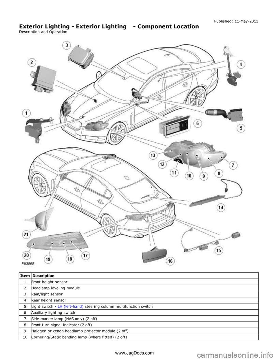
1 Front height sensor 2 Headlamp leveling module 3 Rain/light sensor 4 Rear height sensor 5 Light switch - LH (left-hand) steering column multifunction switch 6 Auxiliary lighting switch 7 Side marker lamp (NAS only) (2 off) 8 Front turn signal indicator (2 off) 9 Halogen or xenon headlamp projector module (2 off) 10 Cornering/Static bending lamp (where fitted) (2 off) www.JagDocs.com