compression ratio JAGUAR XFR 2010 1.G Workshop Manual
[x] Cancel search | Manufacturer: JAGUAR, Model Year: 2010, Model line: XFR, Model: JAGUAR XFR 2010 1.GPages: 3039, PDF Size: 58.49 MB
Page 10 of 3039

211-05: Steering Column Switches
Description and OperationComponent Location
Overview
System Operation and Component DescriptionDiagnosis and TestingSteering Column SwitchesRemoval and InstallationHazard Flasher Switch
Steering Column Multifunction Switch LH
Steering Column Multifunction Switch RH
Steering Column Lock Actuator3: Powertrain
303: Engine
303-00: Engine System - General Information
Diagnosis and TestingEngine - 5.0LGeneral ProceduresBearing Inspection
Camshaft Bearing Journal Diameter
Camshaft End Play
Camshaft Lobe Lift
Camshaft Surface Inspection
Connecting Rod Cleaning
Connecting Rod Large End Bore
Crankshaft End Play
Cylinder Bore Out-of-Round
Exhaust Manifold Cleaning and Inspection
Leakage Test Using Smoke Test Equipment
Piston Inspection
Piston Pin Diameter
Piston Pin to Bore Diameter
Piston Ring End Gap
Piston Ring-to-Groove Clearance
Valve Spring Free Length
Valve Stem Diameter
Cylinder Head Distortion
Cylinder Compression Test - V8 S/C 5.0L Petrol303-01D: Engine - V8 S/C 5.0L PetrolSpecificationDescription and OperationComponent Location
Page 744 of 3039

1 Return fluid control groove 2 Radial groove 3 Feed fluid control groove 4 Radial groove 5 Axial groove 6 Feed fluid control edge 7 Feed fluid radial groove 8 Return fluid control edge 9 Return fluid chamber 10 Cut-off valve 11 Radial groove 12 Servotronic transducer valve 13 Feed fluid radial groove 14 Radial groove 15 Orifice 16 Balls 17 Compression spring 18 Torsion bar 19 Power steering fluid reservoir 20 Valve rotor 21 Reaction piston 22 Reaction chamber 23 Centering piece 24 Pressure relief/flow limiting valve 25 Power steering pump 26 Inner tie-rod 27 Pinion 28 Valve sleeve 29 Steering gear rack 30 Steering gear housing 31 Power assist cylinder - right 32 Piston 33 Power assist cylinder - left When the steering wheel is turned to the right, the steering rack and piston moves to the left in the piston bore. The valve
rotor is rotated to the right (clockwise) and pressurized fluid is directed over the further opened feed fluid control edges and to
the associated axial grooves, the radial groove and via an external pipe to the left power assist cylinder chamber. The pressure
applied to the piston from the left power assist cylinder chamber provides the hydraulic assistance.
An adaptable pressure build-up is achieved by the partially or fully closed feed fluid control edges restricting or preventing a
connection between the fluid pressure inlet and the other axial grooves connected to the radial groove.
Simultaneously, the fluid pressure outlet to the pressurized axial grooves are restricted or partially restricted by the closing
return fluid control edges. The fluid displaced by the piston from the right power assist cylinder chamber, flows through an
external pipe to the radial grooves. From there the fluid passes to the associated axial grooves and on to the return fluid
control grooves, via the further opened return fluid control edges.
The return flow of fluid to the reservoir passes via interconnecting bores which lead to the return fluid chamber. When the
steering wheel is turned to the left the operating sequence is as above but the pressure is applied to the opposite side of the
piston.
Servotronic Operation
The Servotronic software contains a number of steering maps which are selected via the car configuration file depending on the
vehicle mode and tire fitment.
If a failure of the Servotronic valve or software occurs, the system will suspend Servotronic assistance and only normal power
steering wheel be available. Fault codes relating to the fault are stored, but no warning lamps are illuminated and the driver
may be aware of the steering being 'heavier' than usual.
When the vehicle is manoeuvred into and out of a parking space (or other similar manoeuvre), the Servotronic software uses
road speed data from the ABS module to determine the vehicle speed, which in this case will be slow or stationary. The
Servotronic software analyses the signals and outputs an appropriate control current to the Servotronic transducer valve. The
Servotronic valve closes and prevents fluid flowing from the feed fluid radial groove to the reaction chamber. An orifice also
Page 811 of 3039
Engine System - General Information - Engine 5.0L
Diagnosis and Testing
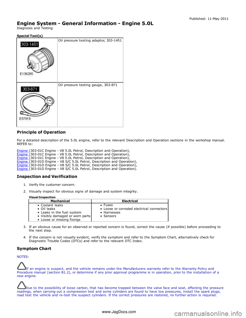
Special Tool(s)
Oil pressure testing adaptor, 303-1451
Oil pressure testing gauge, 303-871 Principle of Operation Published: 11-May-2011
For a detailed description of the 5.0L engine, refer to the relevant Description and Operation sections in the workshop manual.
REFER to:
Engine (303-01C Engine - V8 5.0L Petrol, Description and Operation), Engine (303-01C Engine - V8 5.0L Petrol, Description and Operation), Engine (303-01C Engine - V8 5.0L Petrol, Description and Operation), Engine (303-01D Engine - V8 S/C 5.0L Petrol, Description and Operation), Engine (303-01D Engine - V8 S/C 5.0L Petrol, Description and Operation), Engine (303-01D Engine - V8 S/C 5.0L Petrol, Description and Operation).
Inspection and Verification
1. Verify the customer concern.
2. Visually inspect for obvious signs of damage and system integrity.
Visual Inspection
Mechanical Electrical Coolant leaks
Oil leaks
Leaks in the fuel system
Visibly damaged or worn parts
Loose or missing fixings Fuses
Loose or corroded electrical connectors
Harnesses
Sensors
3. If an obvious cause for an observed or reported concern is found, correct the cause (if possible) before proceeding to
the next step.
4. If the concern is not visually evident, verify the symptom and refer to the Symptom Chart, alternatively check for
Diagnostic Trouble Codes (DTCs) and refer to the relevant DTC Index.
Symptom Chart
NOTES:
If an engine is suspect, and the vehicle remains under the Manufacturers warranty refer to the Warranty Policy and
Procedure manual (section B1.2), or determine if any prior approval programme is in operation, prior to the installation of a
new engine.
Due to the possibility of loose carbon, that has become trapped between the valve face and seat, effecting the pressure
readings, when carrying out a compression test and some cylinders are found to have low pressures, install the spark plugs,
road test the vehicle and re-test the suspect cylinders. If the correct pressures are restored, no further action is required. www.JagDocs.com
Page 814 of 3039
engine oil).
Oil Consumption Test
The amount of oil an engine uses will vary with the way the vehicle is driven in addition to normal engine-to-engine variation.
This is especially true during the first 16,100 km (10,000 miles) when a new engine is being broken in or until certain internal
components become conditioned. Vehicles used in heavy-duty operation may use more oil. The following are examples of
heavy-duty operation:
Trailer towing applications
Severe loading applications
Sustained high speed operation
Engines need oil to lubricate the following internal components:
Cylinder block cylinder walls
Pistons and piston rings
Intake and exhaust valve stems
Intake and exhaust valve guides
All internal engine components
When the pistons move downward, a thin film of oil is left on the cylinder walls. As the vehicle is operated, some oil is also
drawn into the combustion chambers past the intake and exhaust valve stem seals and burned.
The following are examples of conditions that can affect oil consumption rates:
Engine size
Operator driving habits
Ambient temperatures
Quality and viscosity of oil
Engine is being run in an overfilled condition (check the oil level at least five minutes after a hot shutdown with the
vehicle parked on a level surface. The oil level should not be above the top of the cross-hatched area and the letter "F"
in FULL).
Operation under varying conditions can frequently be misleading. A vehicle that has been run for several thousand miles on
short trips or in below-freezing ambient temperatures may have consumed a "normal" amount of oil. However, when checking
the engine oil level, it may measure up to the full mark on the oil level indicator due to dilution (condensation and fuel) in the
engine crankcase. The vehicle then might be driven at high speeds on the highway where the condensation and fuel boil off.
The next time the engine oil is checked it may appear that a liter of oil was used in about 160 km (100 miles). Oil
consumption rate is about one liter per 2,400 km (1,500 miles).
Make sure the selected engine oil meets Jaguar specification and the recommended API performance category "SG" and SAE
viscosity grade as shown in the vehicle Owner's Guide. It is also important that the engine oil is changed at the intervals
specified for the typical operating conditions.
The following diagnostic procedure is used to determine the source of excessive oil consumption.
NOTE: Oil use is normally greater during the first 16,100 km (10,000 miles) of service. As mileage increases, oil use
decreases. High speed driving, towing, high ambient temperature and other factors may result in greater oil use.
1. Define excessive consumption, such as the number of miles driven per liter of oil used. Also determine customers
driving habits, such as sustained high speed operation, towing, extended idle and other considerations.
2. Verify that the engine has no external oil leaks as described under Engine Oil Leaks in this section.
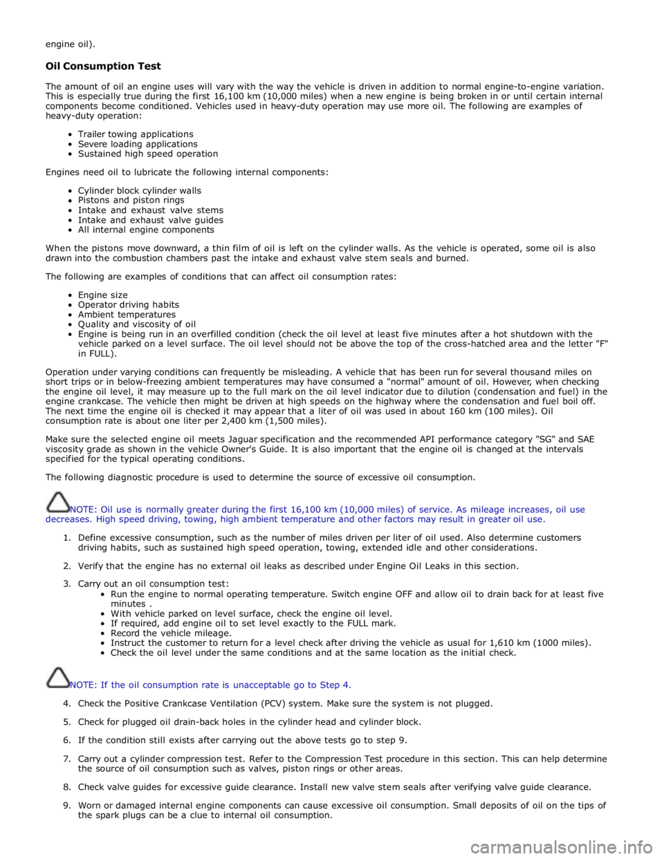
3. Carry out an oil consumption test:
Run the engine to normal operating temperature. Switch engine OFF and allow oil to drain back for at least five
minutes .
With vehicle parked on level surface, check the engine oil level.
If required, add engine oil to set level exactly to the FULL mark.
Record the vehicle mileage.
Instruct the customer to return for a level check after driving the vehicle as usual for 1,610 km (1000 miles).
Check the oil level under the same conditions and at the same location as the initial check.
NOTE: If the oil consumption rate is unacceptable go to Step 4.
4. Check the Positive Crankcase Ventilation (PCV) system. Make sure the system is not plugged.
5. Check for plugged oil drain-back holes in the cylinder head and cylinder block.
6. If the condition still exists after carrying out the above tests go to step 9.
7. Carry out a cylinder compression test. Refer to the Compression Test procedure in this section. This can help determine
the source of oil consumption such as valves, piston rings or other areas.
8. Check valve guides for excessive guide clearance. Install new valve stem seals after verifying valve guide clearance.
9. Worn or damaged internal engine components can cause excessive oil consumption. Small deposits of oil on the tips of
the spark plugs can be a clue to internal oil consumption.
Page 839 of 3039
Published: 09-Apr-2014
Engine System - General Information - Cylinder Compression Test V8 S/C 5.0L
Petrol
General Procedures
Check
CAUTION: Before disconnecting or removing components, make sure the area around the joint faces and connections are
clean. Plug open connections to prevent contamination.
NOTES:
Removal steps in this procedure may contain installation details.
Some variation in the illustrations may occur, but the essential information is always correct.
The vehicle battery must be in good condition and fully charged before carrying out this procedure.
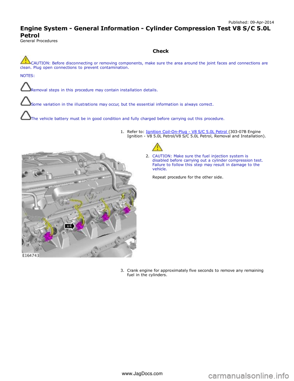
1. Refer to: Ignition Coil-On-Plug - V8 S/C 5.0L Petrol (303-07B Engine Ignition - V8 5.0L Petrol/V8 S/C 5.0L Petrol, Removal and Installation).
2. CAUTION: Make sure the fuel injection system is
disabled before carrying out a cylinder compression test.
Failure to follow this step may result in damage to the
vehicle.
Repeat procedure for the other side.
3. Crank engine for approximately five seconds to remove any remaining
fuel in the cylinders. www.JagDocs.com
Page 844 of 3039
Engine - V8 S/C 5.0L Petrol -
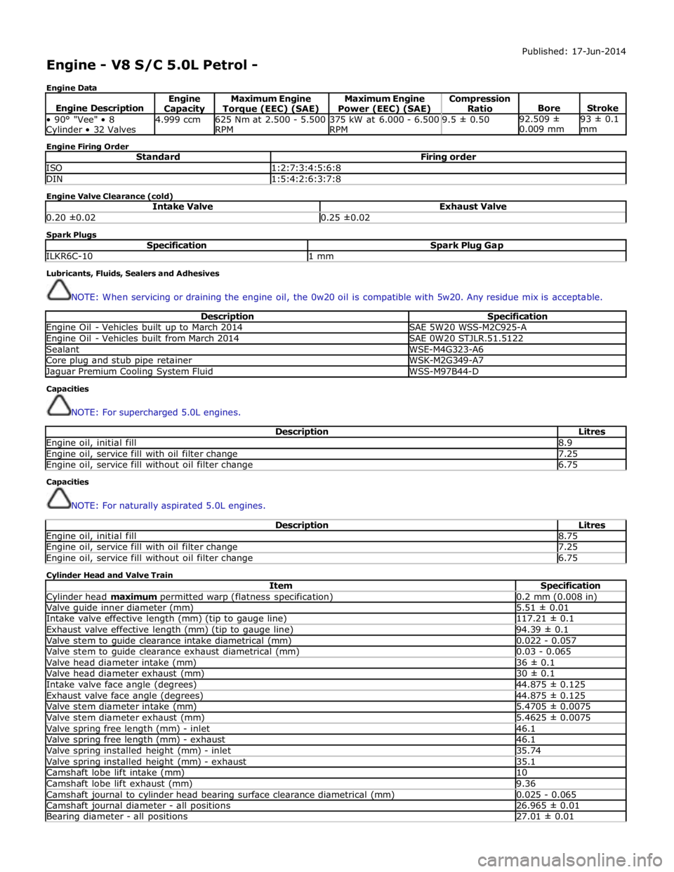
Engine Data Published: 17-Jun-2014
Engine Description Engine Capacity Maximum Engine Torque (EEC) (SAE) Maximum Engine
Power (EEC) (SAE) Compression
Ratio
Bore
Stroke • 90° "Vee" • 8 Cylinder • 32 Valves 4.999 ccm
625 Nm at 2.500 - 5.500
RPM 375 kW at 6.000 - 6.500
RPM 9.5 ± 0.50 92.509 ±
0.009 mm 93 ± 0.1
mm Engine Firing Order
Standard Firing order ISO 1:2:7:3:4:5:6:8 DIN 1:5:4:2:6:3:7:8 Engine Valve Clearance (cold)
Intake Valve Exhaust Valve 0.20 ±0.02 0.25 ±0.02 Spark Plugs
Specification Spark Plug Gap ILKR6C-10 1 mm Lubricants, Fluids, Sealers and Adhesives
NOTE: When servicing or draining the engine oil, the 0w20 oil is compatible with 5w20. Any residue mix is acceptable.
Description Specification Engine Oil - Vehicles built up to March 2014 SAE 5W20 WSS-M2C925-A Engine Oil - Vehicles built from March 2014 SAE 0W20 STJLR.51.5122 Sealant WSE-M4G323-A6 Core plug and stub pipe retainer WSK-M2G349-A7 Jaguar Premium Cooling System Fluid WSS-M97B44-D Capacities
NOTE: For supercharged 5.0L engines.
Description Litres Engine oil, initial fill 8.9 Engine oil, service fill with oil filter change 7.25 Engine oil, service fill without oil filter change 6.75 Capacities
NOTE: For naturally aspirated 5.0L engines.
Description Litres Engine oil, initial fill 8.75 Engine oil, service fill with oil filter change 7.25 Engine oil, service fill without oil filter change 6.75 Cylinder Head and Valve Train
Item Specification Cylinder head maximum permitted warp (flatness specification) 0.2 mm (0.008 in) Valve guide inner diameter (mm) 5.51 ± 0.01 Intake valve effective length (mm) (tip to gauge line) 117.21 ± 0.1 Exhaust valve effective length (mm) (tip to gauge line) 94.39 ± 0.1 Valve stem to guide clearance intake diametrical (mm) 0.022 - 0.057 Valve stem to guide clearance exhaust diametrical (mm) 0.03 - 0.065 Valve head diameter intake (mm) 36 ± 0.1 Valve head diameter exhaust (mm) 30 ± 0.1 Intake valve face angle (degrees) 44.875 ± 0.125 Exhaust valve face angle (degrees) 44.875 ± 0.125 Valve stem diameter intake (mm) 5.4705 ± 0.0075 Valve stem diameter exhaust (mm) 5.4625 ± 0.0075 Valve spring free length (mm) - inlet 46.1 Valve spring free length (mm) - exhaust 46.1 Valve spring installed height (mm) - inlet 35.74 Valve spring installed height (mm) - exhaust 35.1 Camshaft lobe lift intake (mm) 10 Camshaft lobe lift exhaust (mm) 9.36 Camshaft journal to cylinder head bearing surface clearance diametrical (mm) 0.025 - 0.065 Camshaft journal diameter - all positions 26.965 ± 0.01 Bearing diameter - all positions 27.01 ± 0.01
Page 862 of 3039
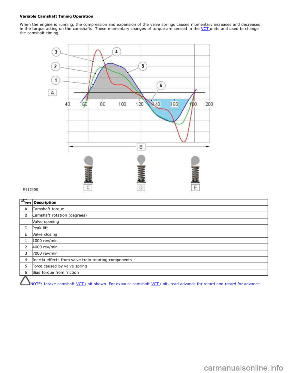
Variable Camshaft Timing Operation
When the engine is running, the compression and expansion of the valve springs causes momentary increases and decreases
in the torque acting on the camshafts. These momentary changes of torque are sensed in the VCT units and used to change the camshaft timing.
ItC
em Description A Camshaft torque B Camshaft rotation (degrees) Valve opening D Peak lift E Valve closing 1 1000 rev/min 2 4000 rev/min 3 7000 rev/min 4 Inertia effects from valve train rotating components 5 Force caused by valve spring 6 Bias torque from friction
NOTE: Intake camshaft VCT unit shown. For exhaust camshaft VCT unit, read advance for retard and retard for advance.