headlamp JAGUAR XFR 2010 1.G Workshop Manual
[x] Cancel search | Manufacturer: JAGUAR, Model Year: 2010, Model line: XFR, Model: JAGUAR XFR 2010 1.GPages: 3039, PDF Size: 58.49 MB
Page 2 of 3039

Table of ContentsContents1: General Information
100: Service Information
100-00: General Information
Description and OperationAbout This Manual
Application and Use of Specifications
Battery and Battery Charging Health and Safety Precautions
Brake System Health and Safety Precautions
Diesel Fuel System Health and Safety Precautions
General Service Information
Health and Safety Precautions
How To Use This Manual
Important Safety Instructions
Petrol and Petrol-Ethanol Fuel Systems Health and Safety Precautions
Solvents, Sealants and Adhesives
Standard Workshop Practices
Symbols Glossary
Supplemental Restraint System (SRS) Health and Safety Precautions
Road/Roller Testing
Window Glass Health and Safety Precautions
Diagnostic Trouble Code (DTC) IndexDTC: Adaptive Damping Module (SUMB)
Diagnostic Trouble Code (DTC) IndexDTC: Anti-Lock Braking System (ABS)
Diagnostic Trouble Code (DTC) IndexDTC: Audio Amplifier Module (AAM)
Diagnostic Trouble Code (DTC) IndexDTC: Blind Spot Monitoring System Module (SODL/SODR)
Diagnostic Trouble Code (DTC) IndexDTC: Central Junction Box (CJB)
Diagnostic Trouble Code (DTC) IndexDTC: Climate Control Module (HVAC)
Diagnostic Trouble Code (DTC) IndexDTC: Digital Audio Broadcast Module (DABM)
Diagnostic Trouble Code (DTC) IndexDTC: Driver Door Module/Passenger Door Module (DDM/PDM)
Diagnostic Trouble Code (DTC) IndexDTC: Driver/Passenger Seat Module (DSM/PSM)
Diagnostic Trouble Code (DTC) IndexDTC: Electric Parking Brake (PBM)
Diagnostic Trouble Code (DTC) Index V8 S/C 5.0L Petrol, DTC: Engine Control Module (ECM)
Diagnostic Trouble Code (DTC) IndexDTC: Front Seat Climate Control Module (DCSM)
Diagnostic Trouble Code (DTC) IndexDTC: Headlamp Control Module (HCM)
Diagnostic Trouble Code (DTC) IndexDTC: Instrument Cluster (IPC)
Diagnostic Trouble Code (DTC) IndexDTC: Integrated Audio Module (IAM)
Diagnostic Trouble Code (DTC) IndexDTC: Integrated Control Panel (FCIMB)
Page 22 of 3039

Operation and
Component DescriptionCellular PhoneComponent
Location
Overview
System Operation
and Component DescriptionNavigation SystemComponent Location
Overview
System Operation and Component DescriptionVideo SystemComponent
Location
Overview
System Operation
and Component DescriptionDiagnosis and TestingInformation and Entertainment SystemRemoval and InstallationAudio Unit
Audio Unit Antenna Amplifier
Audio and Climate Control Assembly
Front Door Speaker
Information and Entertainment Display
Information and Entertainment Module
Instrument Panel Speaker
Rear Door Speaker
Steering Wheel Audio Controls
Subwoofer Amplifier
Subwoofer Speaker
Satellite Radio Tuner415-01B: Information and Entertainment System - DTC: Audio Input Control Module
Diagnosis and TestingAudio Input Control Module417: Lighting
417-01: Exterior LightingSpecificationDescription and OperationComponent Location
Overview
System Operation and Component DescriptionDiagnosis and TestingHeadlampsGeneral ProceduresHeadlamp Adjustment (86.40.18)
Page 23 of 3039

Removal and InstallationApproach Lamp
Headlamp Assembly
Headlamp Leveling Front Sensor
Headlamp Leveling Rear Sensor
High Mounted Stoplamp
Rear Fog Lamp
Rear Lamp Assembly
Side Turn Signal Lamp417-02: Interior Lighting
Description and OperationComponent Location
Overview
System Operation and Component DescriptionDiagnosis and TestingInterior Lighting417-04: Daytime Running Lamps (DRL)
Description and OperationOverview
System Operation and Component Description418: Electrical Distribution
418-00: Module Communications Network
Description and OperationOverview
System Operation and Component DescriptionDiagnosis and TestingCommunications NetworkRemoval and InstallationAuxiliary Junction Box (AJB)
Central Junction Box (CJB)418-02: Wiring Harnesses
Description and OperationWiring HarnessGeneral ProceduresWiring Harness RepairRemoval and InstallationLuggage Compartment Lid Wiring Harness419: Electronic Feature Group
419-01A: Anti-Theft - Active
Description and OperationComponent Location
Overview
Page 28 of 3039

Instrument Panel Console
Instrument Panel Lower Trim Panel
Overhead Console501-14: Handles, Locks, Latches and Entry SystemsSpecificationDescription and OperationComponent Location
Overview
System Operation and Component DescriptionDiagnosis and TestingLocks, Latches and Entry SystemsRemoval and InstallationDoor Lock Cylinder Cover
Exterior Front Door Handle
Exterior Luggage Compartment Lid Release Switch
Exterior Rear Door Handle
Front Door Latch
Front Door Lock Cylinder
Interior Front Door Handle
Luggage Compartment Lid Latch Actuator
Luggage Compartment Lid Lock Cylinder
Rear Door Latch501-16: Wipers and WashersSpecificationDescription and OperationComponent Location
Overview
System Operation and Component DescriptionDiagnosis and TestingWipers and WashersRemoval and InstallationHeadlamp Washer Jet
Headlamp Washer Pump
Rain Sensor
Windshield Washer Reservoir
Windshield Wiper Motor
Windshield Wiper Pivot Arm
Windshield Washer Pump501-17: Roof Opening PanelSpecificationDescription and OperationComponent Location
Page 183 of 3039

Published: 12-May-2014
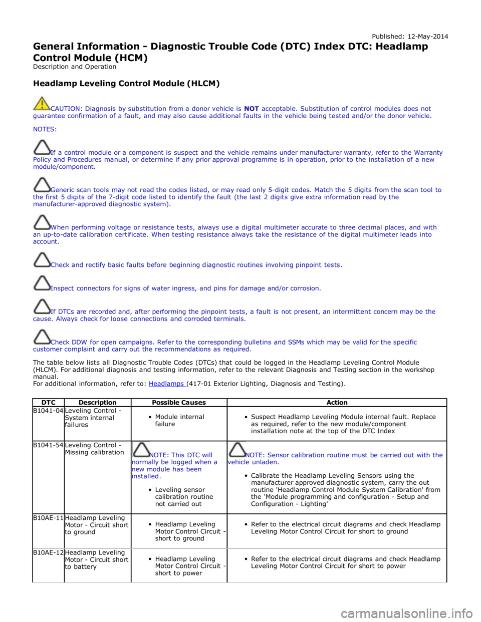
General Information - Diagnostic Trouble Code (DTC) Index DTC: Headlamp
Control Module (HCM)
Description and Operation
Headlamp Leveling Control Module (HLCM)
CAUTION: Diagnosis by substitution from a donor vehicle is NOT acceptable. Substitution of control modules does not
guarantee confirmation of a fault, and may also cause additional faults in the vehicle being tested and/or the donor vehicle.
NOTES:
If a control module or a component is suspect and the vehicle remains under manufacturer warranty, refer to the Warranty
Policy and Procedures manual, or determine if any prior approval programme is in operation, prior to the installation of a new
module/component.
Generic scan tools may not read the codes listed, or may read only 5-digit codes. Match the 5 digits from the scan tool to
the first 5 digits of the 7-digit code listed to identify the fault (the last 2 digits give extra information read by the
manufacturer-approved diagnostic system).
When performing voltage or resistance tests, always use a digital multimeter accurate to three decimal places, and with
an up-to-date calibration certificate. When testing resistance always take the resistance of the digital multimeter leads into
account.
Check and rectify basic faults before beginning diagnostic routines involving pinpoint tests.
Inspect connectors for signs of water ingress, and pins for damage and/or corrosion.
If DTCs are recorded and, after performing the pinpoint tests, a fault is not present, an intermittent concern may be the
cause. Always check for loose connections and corroded terminals.
Check DDW for open campaigns. Refer to the corresponding bulletins and SSMs which may be valid for the specific
customer complaint and carry out the recommendations as required.
The table below lists all Diagnostic Trouble Codes (DTCs) that could be logged in the Headlamp Leveling Control Module
(HLCM). For additional diagnosis and testing information, refer to the relevant Diagnosis and Testing section in the workshop
manual.
For additional information, refer to: Headlamps (417-01 Exterior Lighting, Diagnosis and Testing).
DTC Description Possible Causes Action B1041-04
Leveling Control -
System internal
failures
Module internal
failure
Suspect Headlamp Leveling Module internal fault. Replace
as required, refer to the new module/component
installation note at the top of the DTC Index B1041-54
Leveling Control -
Missing calibration
NOTE: This DTC will
normally be logged when a
new module has been
installed.
Leveling sensor
calibration routine
not carried out
NOTE: Sensor calibration routine must be carried out with the
vehicle unladen.
Calibrate the Headlamp Leveling Sensors using the
manufacturer approved diagnostic system, carry the out
routine 'Headlamp Control Module System Calibration' from
the 'Module programming and configuration - Setup and
Configuration - Lighting' B10AE-11
Headlamp Leveling
Motor - Circuit short
to ground
Headlamp Leveling
Motor Control Circuit -
short to ground
Refer to the electrical circuit diagrams and check Headlamp
Leveling Motor Control Circuit for short to ground B10AE-12
Headlamp Leveling
Motor - Circuit short
to battery
Headlamp Leveling
Motor Control Circuit -
short to power
Refer to the electrical circuit diagrams and check Headlamp
Leveling Motor Control Circuit for short to power
Page 184 of 3039

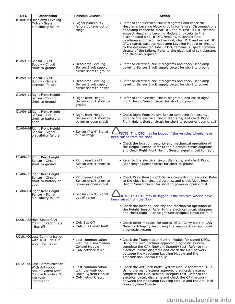
DTC Description Possible Causes Action B10AE-64
Headlamp Leveling
Motor - Signal
plausibility failure
Signal plausibility
failure voltage out of
range
Refer to the electrical circuit diagrams and check the
Headlamp Leveling Motor circuits for failure. Disconnect one
headlamp connector, clear DTC and re-test. If DTC cleared,
suspect Headlamp Leveling Module or circuits to the
disconnected side. If DTC remains, reconnect first
headlamp and disconnect second, clear DTC and re-test. If
DTC cleared, suspect Headlamp Leveling Module or circuits
to the disconnected side. If DTC remains, suspect common
circuits of the failure. Refer to the electrical circuit diagrams
and check as required B1A59-11
Sensor 5 Volt
Supply - Circuit
short to ground
Headlamp Leveling
Sensor 5 volt supply
circuit short to ground
Refer to electrical circuit diagrams and check Headlamp
Leveling Sensor 5 volt supply circuit for short to ground B1A59-12
Sensor 5 Volt
Supply - General
electrical failure
Headlamp Leveling
Sensor 5 volt supply
circuit short to power
Refer to electrical circuit diagrams and check Headlamp
Leveling Sensor 5 volt supply circuit for short to power C1A04-11
Right Front Height
Sensor - Circuit
short to ground
Right front Height
Sensor circuit short to
ground
Refer to the electrical circuit diagrams, and check Right
Front Height Sensor circuit for short to ground C1A04-15
Right Front Height
Sensor - Circuit
short to battery or
open
Right front Height
Sensor circuit short to
power or open circuit
Check Right Front Height Sensor connector for security.
Refer to the electrical circuit diagrams, and check Right
Front Height Sensor circuit for short to power or open circuit C1A04-64
Right Front Height
Sensor - Signal
plausibility failure
Sensor (PWM) Signal
out of range
NOTE: This DTC may be logged if the vehicles wheels have
been raised from the floor
Check the location, security and mechanical operation of
the Height Sensor. Refer to the electrical circuit diagrams,
and check Right Front Height Sensor signal circuit for fault C1A06-11
Right Rear Height
Sensor - Circuit
short to ground
Right rear Height
Sensor circuit short to
ground
Refer to the electrical circuit diagrams, and check Right
Rear Height Sensor circuit for short to ground C1A06-15
Right Rear Height
Sensor - Circuit
short to battery or
open
Right rear Height
Sensor circuit short to
power or open circuit
Check Right Rear Height Sensor connector for security. Refer
to the electrical circuit diagrams, and check Right Rear
Height Sensor circuit for short to power or open circuit C1A06-64
Right Rear Height
Sensor - Signal
plausibility failure
Sensor (PWM) Signal
out of range
NOTE: This DTC may be logged if the vehicles wheels have
been raised from the floor
Check the location, security and mechanical operation of
the Height Sensor. Refer to the electrical circuit diagrams,
and check Right Rear Height Sensor signal circuit for fault U0001-88
High Speed CAN
Communication Bus
- Bus off
CAN Bus Off
CAN Bus Circuit fault
Check other modules for stored DTCs. Carry out the CAN
Network Integrity test using the manufacturer approved
diagnostic system U0101-00
Lost Communication
with TCM - No sub
type information
Lost communication
with the Transmission
Control Module
CAN network fault
Check the Transmission Control Module for stored DTCs.
Using the manufacturer approved diagnostic system,
complete the CAN Network Integrity test. Refer to the
electrical circuit diagrams and check the CAN network
between the Headlamp Leveling Module and the
Transmission Control Module U0121-00
Lost Communication
With Anti-Lock
Brake System (ABS)
Control Module - No
sub type
information
Lost communication
with the Anti-lock
Brake System Module
CAN network fault
Check the Anti-lock Brake System Module for stored DTCs.
Using the manufacturer approved diagnostic system,
complete the CAN Network Integrity test. Refer to the
electrical circuit diagrams and check the CAN network
between the Headlamp Leveling Module and the Anti-lock
Brake System Module
Page 185 of 3039

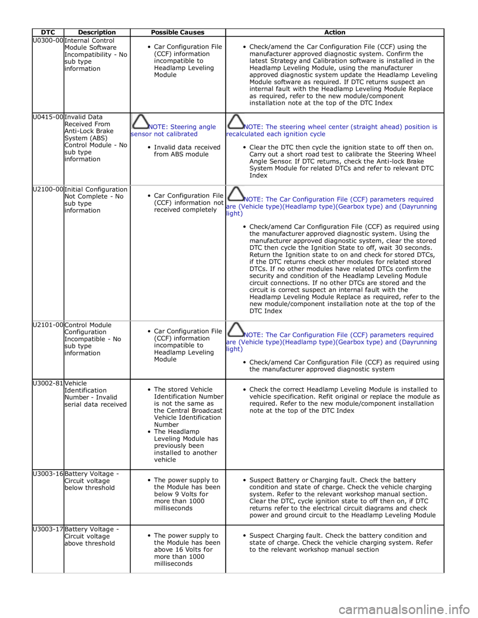
DTC Description Possible Causes Action U0300-00
Internal Control
Module Software
Incompatibility - No
sub type
information
Car Configuration File
(CCF) information
incompatible to
Headlamp Leveling
Module
Check/amend the Car Configuration File (CCF) using the
manufacturer approved diagnostic system. Confirm the
latest Strategy and Calibration software is installed in the
Headlamp Leveling Module, using the manufacturer
approved diagnostic system update the Headlamp Leveling
Module software as required. If DTC returns suspect an
internal fault with the Headlamp Leveling Module Replace
as required, refer to the new module/component
installation note at the top of the DTC Index U0415-00
Invalid Data
Received From
Anti-Lock Brake
System (ABS)
Control Module - No
sub type
information
NOTE: Steering angle
sensor not calibrated
Invalid data received
from ABS module
NOTE: The steering wheel center (straight ahead) position is
recalculated each ignition cycle
Clear the DTC then cycle the ignition state to off then on.
Carry out a short road test to calibrate the Steering Wheel
Angle Sensor. If DTC returns, check the Anti-lock Brake
System Module for related DTCs and refer to relevant DTC
Index U2100-00
Initial Configuration
Not Complete - No
sub type
information
Car Configuration File
(CCF) information not
received completely
NOTE: The Car Configuration File (CCF) parameters required
are (Vehicle type)(Headlamp type)(Gearbox type) and (Dayrunning
light)
Check/amend Car Configuration File (CCF) as required using
the manufacturer approved diagnostic system. Using the
manufacturer approved diagnostic system, clear the stored
DTC then cycle the Ignition State to off, wait 30 seconds.
Return the Ignition state to on and check for stored DTCs,
if the DTC returns check other modules for related stored
DTCs. If no other modules have related DTCs confirm the
security and condition of the Headlamp Leveling Module
circuit connections. If no other DTCs are stored and the
circuit is correct suspect an internal fault with the
Headlamp Leveling Module Replace as required, refer to the
new module/component installation note at the top of the
DTC Index U2101-00
Control Module
Configuration
Incompatible - No
sub type
information
Car Configuration File
(CCF) information
incompatible to
Headlamp Leveling
Module
NOTE: The Car Configuration File (CCF) parameters required
are (Vehicle type)(Headlamp type)(Gearbox type) and (Dayrunning
light)
Check/amend Car Configuration File (CCF) as required using
the manufacturer approved diagnostic system U3002-81
Vehicle
Identification
Number - Invalid
serial data received
The stored Vehicle
Identification Number
is not the same as
the Central Broadcast
Vehicle Identification
Number
The Headlamp
Leveling Module has
previously been
installed to another
vehicle
Check the correct Headlamp Leveling Module is installed to
vehicle specification. Refit original or replace the module as
required. Refer to the new module/component installation
note at the top of the DTC Index U3003-16
Battery Voltage -
Circuit voltage
below threshold
The power supply to
the Module has been
below 9 Volts for
more than 1000
milliseconds
Suspect Battery or Charging fault. Check the battery
condition and state of charge. Check the vehicle charging
system. Refer to the relevant workshop manual section.
Clear the DTC, cycle ignition state to off then on, if DTC
returns refer to the electrical circuit diagrams and check
power and ground circuit to the Headlamp Leveling Module U3003-17
Battery Voltage -
Circuit voltage
above threshold
The power supply to
the Module has been
above 16 Volts for
more than 1000
milliseconds
Suspect Charging fault. Check the battery condition and
state of charge. Check the vehicle charging system. Refer
to the relevant workshop manual section
Page 186 of 3039

DTC Description Possible Causes Action U3003-62
Battery Voltage -
Signal compare
failure
Difference in battery
voltage, of 2 volts or
more, between the
central broadcast
voltage (via CAN Bus)
and Headlamp
Leveling Module
Check other modules for related stored DTCs. Refer to the
electrical circuit diagrams and check power and ground
voltages at the Headlamp Leveling Module U0428-00
Invalid Data
Received From
Steering Angle
Sensor Module - No
sub type
information
NOTE: Steering Angle
Sensor not calibrated
Invalid Data Received
from the Steering
Angle Sensor Module
Check the Steering Angle Sensor Module for stored DTCs.
Using the manufacturer approved diagnostic system,
complete the CAN Network Integrity test. Refer to the
electrical circuit diagrams and check the CAN network
between the Headlamp Leveling Module and the
Transmission Control Module U0402-00
Invalid Data
Received From
Transmission
Control Module - No
sub type
information
Invalid Data Received
from the
Transmission Control
Module
Transmission
component fault
Check the Transmission Control Module for stored DTCs.
Using the manufacturer approved diagnostic system,
complete the CAN Network Integrity test. Refer to the
electrical circuit diagrams and check the CAN network
between the Headlamp Leveling Module and the
Transmission Control Module U0126-00
Lost Communication
With Steering Angle
Sensor Module - No
sub type
information
Lost communication
with the Steering
Angle Sensor Module
CAN network fault
Check the Steering Angle Sensor Module for stored DTCs.
Using the manufacturer approved diagnostic system,
complete the CAN Network Integrity test. Refer to the
electrical circuit diagrams and check the CAN network
between the Headlamp Leveling Module and the Steering
Angle Sensor U0142-00 Lost Communication
Lost communication
Check the Auxiliary Junction Box for stored DTCs. Using the With Body Control Module "B" - No sub with the Auxiliary manufacturer approved diagnostic system, complete the type information Junction Box CAN Network Integrity test. Refer to the electrical circuit CAN network fault diagrams and check the CAN network between the Headlamp Leveling Module and the Auxiliary Junction Box www.JagDocs.com
Page 486 of 3039

2 Main piston 3 Tube 4 Bypass valve (closed) 5 Piston and rod assembly ACCELEROMETERS
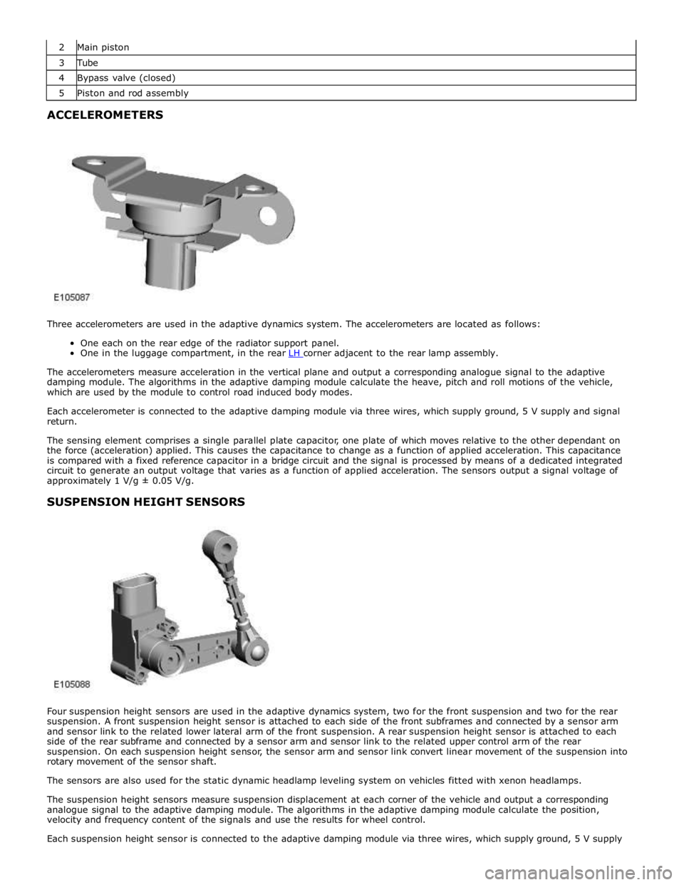
Three accelerometers are used in the adaptive dynamics system. The accelerometers are located as follows:
One each on the rear edge of the radiator support panel.
One in the luggage compartment, in the rear LH corner adjacent to the rear lamp assembly.
The accelerometers measure acceleration in the vertical plane and output a corresponding analogue signal to the adaptive
damping module. The algorithms in the adaptive damping module calculate the heave, pitch and roll motions of the vehicle,
which are used by the module to control road induced body modes.
Each accelerometer is connected to the adaptive damping module via three wires, which supply ground, 5 V supply and signal
return.
The sensing element comprises a single parallel plate capacitor, one plate of which moves relative to the other dependant on
the force (acceleration) applied. This causes the capacitance to change as a function of applied acceleration. This capacitance
is compared with a fixed reference capacitor in a bridge circuit and the signal is processed by means of a dedicated integrated
circuit to generate an output voltage that varies as a function of applied acceleration. The sensors output a signal voltage of
approximately 1 V/g ± 0.05 V/g.
SUSPENSION HEIGHT SENSORS
Four suspension height sensors are used in the adaptive dynamics system, two for the front suspension and two for the rear
suspension. A front suspension height sensor is attached to each side of the front subframes and connected by a sensor arm
and sensor link to the related lower lateral arm of the front suspension. A rear suspension height sensor is attached to each
side of the rear subframe and connected by a sensor arm and sensor link to the related upper control arm of the rear
suspension. On each suspension height sensor, the sensor arm and sensor link convert linear movement of the suspension into
rotary movement of the sensor shaft.
The sensors are also used for the static dynamic headlamp leveling system on vehicles fitted with xenon headlamps.
The suspension height sensors measure suspension displacement at each corner of the vehicle and output a corresponding
analogue signal to the adaptive damping module. The algorithms in the adaptive damping module calculate the position,
velocity and frequency content of the signals and use the results for wheel control.
Each suspension height sensor is connected to the adaptive damping module via three wires, which supply ground, 5 V supply
Page 797 of 3039

Published: 11-May-2011
Steering Column Switches - Steering Column Switches - Overview
Description and Operation
OVERVIEW
The steering column multifunction switch is situated on the steering column and consists of the wiper switch, the turn signal
indicator/lighting switch and the trip computer switch.
The RH (right-hand) multifunction switch controls the following windshield wiper functions:
Flick wipe
Intermittent wipe
Slow speed wipe
High speed wipe
Wash/Wipe
Headlamp powerwash
Rain sensing / variable wipe selection.
The LH (left-hand) multifunction switch controls the following functions:
Turn signal indicators
Side lamps
Headlamps
Auto lamps
High/low beam
Headlamp flash
Headlamp timer
Trip computer.
The steering column adjustment switch is located in the steering column lower shroud on the LH side. The switch is a 4 position 'joystick' which controls reach and rake adjustment.
The trip button allows the driver to cycle though an option menu and also reset trip cycle mileage calculations. The trip
computer information is displayed in the instrument cluster message centre.
Steering wheel mounted switches on the LH side of the driver's airbag, control the audio and telephone functions. Switches on the RH side of the driver's airbag, control the speed control functions. The steering wheel has an internal heating element. This is controlled by the driver via the Touch Screen Display (TSD). www.JagDocs.com