pinpoint JAGUAR XFR 2010 1.G Workshop Manual
[x] Cancel search | Manufacturer: JAGUAR, Model Year: 2010, Model line: XFR, Model: JAGUAR XFR 2010 1.GPages: 3039, PDF Size: 58.49 MB
Page 2419 of 3039

Glass, Frames and Mechanisms - Fixed Window Glass
Diagnosis and Testing
Principles of Operation Published: 09-Apr-2014
For a detailed description of the Glass, Frames and Mechanisms, refer to the relevant Description and Operation section in the
workshop manual.
Inspection and Verification
CAUTION: Diagnosis by substitution from a donor vehicle is NOT acceptable. Substitution of control modules does not
guarantee confirmation of a fault, and may also cause additional faults in the vehicle being tested and/or the donor vehicle.
NOTES:
If a control module or a component is suspect and the vehicle remains under manufacturer warranty, refer to the Warranty
Policy and Procedures manual, or determine if any prior approval programme is in operation, prior to the installation of a new
module/component.
When performing voltage or resistance tests, always use a digital multimeter accurate to three decimal places, and with
an up-to-date calibration certificate. When testing resistance always take the resistance of the digital multimeter leads into
account.
Check and rectify basic faults before beginning diagnostic routines involving pinpoint tests.
Refer to Section 100-00 General Information for window glass health and safety precautions.
1. Verify the customer concern
2. Visually inspect for obvious signs of damage and system integrity
Visual Inspection
3. If an obvious cause for an observed or reported concern is found, correct the cause (if possible) before proceeding to
the next step
4. If the cause is not visually evident, verify the symptom and refer to the Symptom Chart, alternatively check for
Diagnostic Trouble Codes (DTCs) and refer to the DTC Index
5. Check DDW for open campaigns. Refer to the corresponding bulletins and SSMs which may be valid for the specific
customer complaint and carry out the recommendations as required
Warranty Repairs
NOTES:
The warranty period for the windshield is twelve months with the exception of delamination and electrical faults.
Warranty repairs should be completed using genuine parts, in accordance with the Warranty Policy and Procedures
Manual.
1. Draw a line around the windshield damage using a marker pen.
2. Photograph the entire windshield. If the damage extends behind any trim, remove the trim and take further
photographs.
3. Photograph the trademark logo and code to validate the windshield as factory fitment.
Symptom Chart
Symptom Possible Causes Action Scratches
Debris trapped under a wiper blade
GO to Pinpoint Test A. Electrical
Physical damage to the windshield
www.JagDocs.com
Page 2420 of 3039
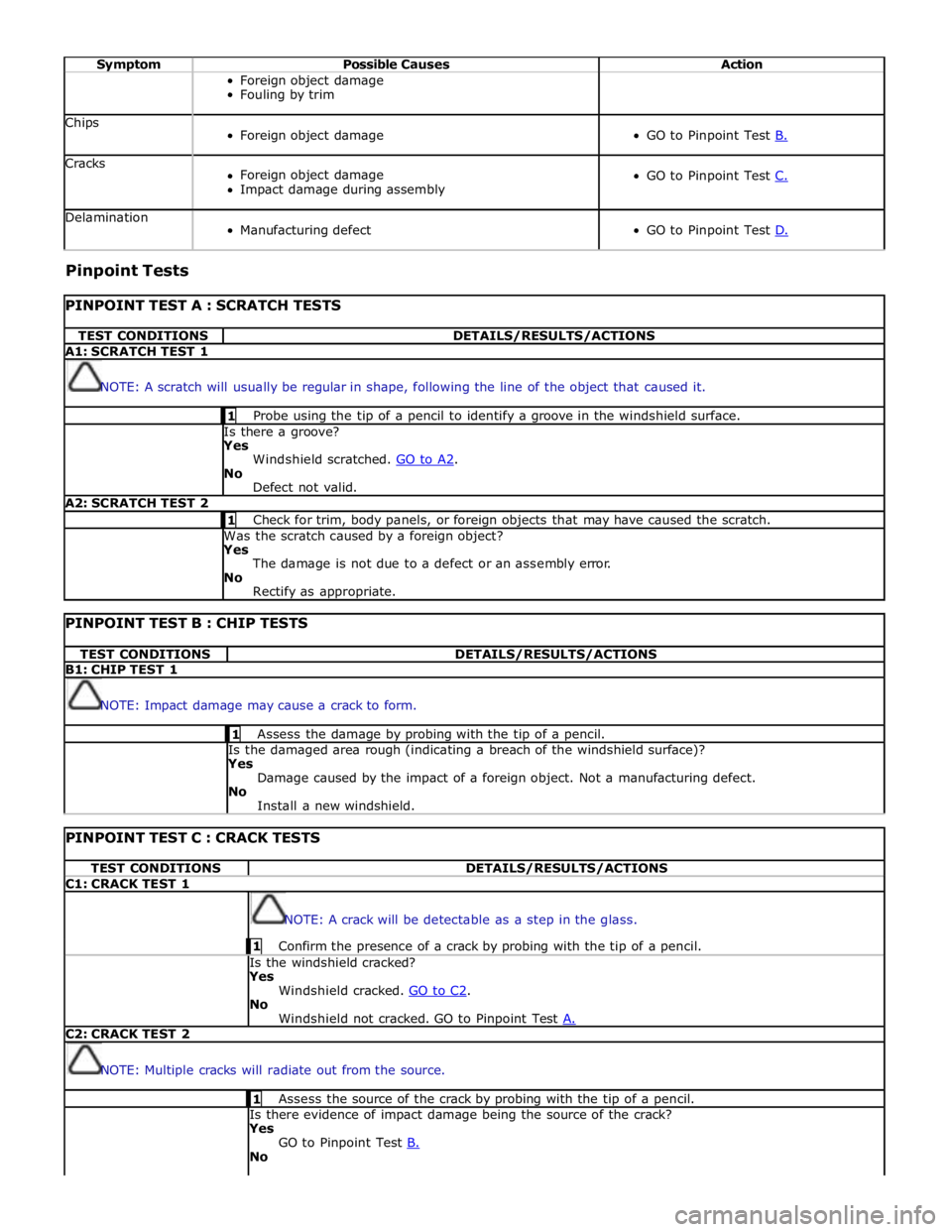
Symptom Possible Causes Action Foreign object damage
Fouling by trim Chips
Foreign object damage
GO to Pinpoint Test B. Cracks
Foreign object damage
Impact damage during assembly
GO to Pinpoint Test C. Delamination
Manufacturing defect
GO to Pinpoint Test D. Pinpoint Tests
PINPOINT TEST A : SCRATCH TESTS TEST CONDITIONS DETAILS/RESULTS/ACTIONS A1: SCRATCH TEST 1
NOTE: A scratch will usually be regular in shape, following the line of the object that caused it. 1 Probe using the tip of a pencil to identify a groove in the windshield surface. Is there a groove? Yes
Windshield scratched. GO to A2. No
Defect not valid. A2: SCRATCH TEST 2 1 Check for trim, body panels, or foreign objects that may have caused the scratch. Was the scratch caused by a foreign object? Yes
The damage is not due to a defect or an assembly error.
No
Rectify as appropriate.
PINPOINT TEST B : CHIP TESTS TEST CONDITIONS DETAILS/RESULTS/ACTIONS B1: CHIP TEST 1
NOTE: Impact damage may cause a crack to form. 1 Assess the damage by probing with the tip of a pencil. Is the damaged area rough (indicating a breach of the windshield surface)? Yes
Damage caused by the impact of a foreign object. Not a manufacturing defect.
No
Install a new windshield.
PINPOINT TEST C : CRACK TESTS TEST CONDITIONS DETAILS/RESULTS/ACTIONS C1: CRACK TEST 1
NOTE: A crack will be detectable as a step in the glass. 1 Confirm the presence of a crack by probing with the tip of a pencil. Is the windshield cracked?
Yes
Windshield cracked. GO to C2. No
Windshield not cracked. GO to Pinpoint Test A. C2: CRACK TEST 2
NOTE: Multiple cracks will radiate out from the source. 1 Assess the source of the crack by probing with the tip of a pencil. Is there evidence of impact damage being the source of the crack?
Yes
GO to Pinpoint Test B. No
Page 2495 of 3039
Published: 18-Mar-2014
Handles, Locks, Latches and Entry Systems - Locks, Latches and Entry Systems
Diagnosis and Testing
Principle of Operation
For a detailed description of the locks, latches and entry systems and operation, refer to the relevant Description and
Operation section of the workshop manual. REFER to: Handles, Locks, Latches and Entry Systems (501-14, Description and
Operation).
Inspection and Verification
CAUTION: Diagnosis by substitution from a donor vehicle is NOT acceptable. Substitution of control modules does not
guarantee confirmation of a fault and may also cause additional faults in the vehicle being checked and/or the donor vehicle
NOTE: Check and rectify basic faults before beginning diagnostic routines involving pinpoint tests
1. Verify the customer concern, to be sure the correct issue is investigated
2. Visually inspect for obvious signs of damage and system integrity
Visual Inspection
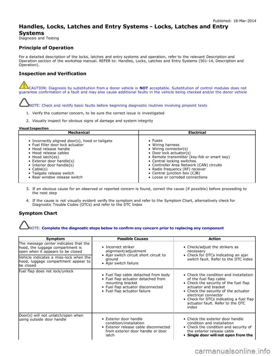
Mechanical Electrical
Incorrectly aligned door(s), hood or tailgate
Fuel filler door lock actuator
Hood release handle
Hood release cables
Hood latch(es)
Exterior door handle(s)
Interior door handle(s)
Cable(s)
Tailgate release switch
Rear window release switch
Fuses
Wiring harness
Wiring connector(s)
Door lock actuator(s)
Remote transmitter (key-fob or smart key)
Central locking switches
Controller Area Network (CAN) circuits
Radio frequency (RF) receiver
Central junction box (CJB)
Loose or corroded connections
3. If an obvious cause for an observed or reported concern is found, correct the cause (if possible) before proceeding to
the next step
4. If the cause is not visually evident verify the symptom and refer to the Symptom Chart, alternatively check for
Diagnostic Trouble Codes (DTCs) and refer to the DTC Index
Symptom Chart
NOTE: Complete the diagnostic steps below to confirm any concern prior to replacing any component
Symptom Possible Causes Action The message center indicates that the
hood, the luggage compartment is
open when it appears to be closed
Incorrect striker
alignment/adjustment
Ajar switch circuit short circuit to
ground
Ajar switch failure
Check/adjust the strikers as
necessary
Check for DTCs indicating an ajar
switch fault. Refer to the DTC index Vehicle indicates a miss-lock when the
hood, luggage compartment appear to
be closed Fuel flap does not lock/unlock
Fuel flap cable detached from body
Fuel flap actuator detached from
mounting bracket
Fuel flap actuator disconnected
Fuel flap actuator failure
Check the condition and installation
of the fuel flap cable
Check the security of the fuel flap
actuator and bracket
Check the security of the actuator
electrical connector
Check for DTCs indicating a fuel flap
actuator fault. Refer to the DTC
index Door(s) will not unlatch/open when
using outside door handle
Exterior door handle
condition/installation
Exterior release cable disconnected
from exterior door handle or door
latch
Check the exterior door handle
condition and installation
Check the condition and security of
the exterior release cable
Single door will not open from the
Page 2496 of 3039

Symptom Possible Causes Action outside (but opens from the
inside) GO to Pinpoint Test A. Door(s) will not unlatch/open when
using inside door handle
Child lock(s) engaged
Interior door handle
condition/installation
Interior release cable disconnected
from interior door handle or door
latch
Check that the child locks are
disengaged
Check the interior door handle
condition and installation
Check the condition and security of
the interior release cable
Single Door Will Not Open From
The Inside (but opens from the
outside) GO to Pinpoint Test B. Door(s) will not lock/unlock from key
fob, key or internal lock switch
Wiring harness/connectors
Central junction box (CJB)
Door lock switch
Cable fault
Check for relevant stored DTCs
Once any DTC related faults have
been rectified continue with the
diagnostic steps below
No lock / unlock function from
key-fob GO to Pinpoint Test C. Door ajar or miss lock signal at
message centre when door(s) are
closed or alarm triggering
Wiring harness
Instrument cluster
Incorrect striker
alignment/adjustment
Ajar switch circuit short circuit to
ground
Ajar switch failure
Latch Mounted Door Ajar Switch
Test GO to Pinpoint Test D. DTC Index
For a list of Diagnostic Trouble Codes (DTCs) that could be logged on this vehicle, please refer to Section 100-00.
REFER to: Communications Network (418-00, Diagnosis and Testing) /
Locks, Latches and Entry Systems - DTC: With (501-14, Diagnosis and Testing).
Pinpoint Test
PINPOINT TEST A : SINGLE DOOR WILL NOT OPEN FROM THE OUTSIDE (BUT OPENS FROM THE INSIDE) TEST CONDITIONS DETAILS/RESULTS/ACTIONS A1: CHECK THE EXTERIOR DOOR RELEASE CABLE TO EXTERIOR DOOR HANDLE IS INSTALLED CORRECTLY
1 Remove the door trim panel as necessary 2 Confirm the exterior door release cable is correctly installed to the exterior door handle Is the cable correctly installed?
Yes
GO to A2. No
Page 2497 of 3039
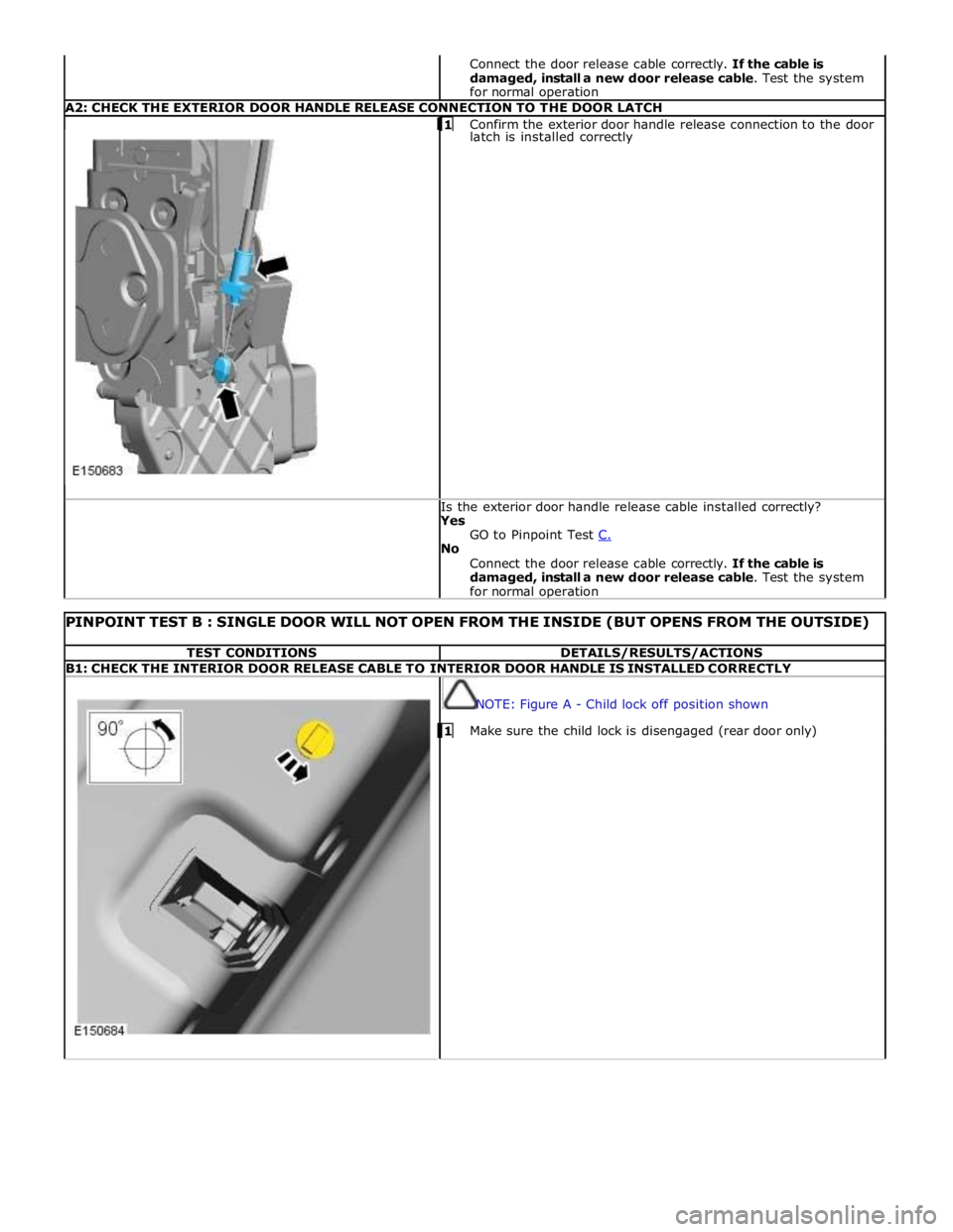
Connect the door release cable correctly. If the cable is
damaged, install a new door release cable. Test the system
for normal operation A2: CHECK THE EXTERIOR DOOR HANDLE RELEASE CONNECTION TO THE DOOR LATCH 1 Confirm the exterior door handle release connection to the door latch is installed correctly Is the exterior door handle release cable installed correctly?
Yes
GO to Pinpoint Test C. No
Connect the door release cable correctly. If the cable is
damaged, install a new door release cable. Test the system
for normal operation
PINPOINT TEST B : SINGLE DOOR WILL NOT OPEN FROM THE INSIDE (BUT OPENS FROM THE OUTSIDE) TEST CONDITIONS DETAILS/RESULTS/ACTIONS B1: CHECK THE INTERIOR DOOR RELEASE CABLE TO INTERIOR DOOR HANDLE IS INSTALLED CORRECTLY
NOTE: Figure A - Child lock off position shown 1 Make sure the child lock is disengaged (rear door only)
Page 2498 of 3039
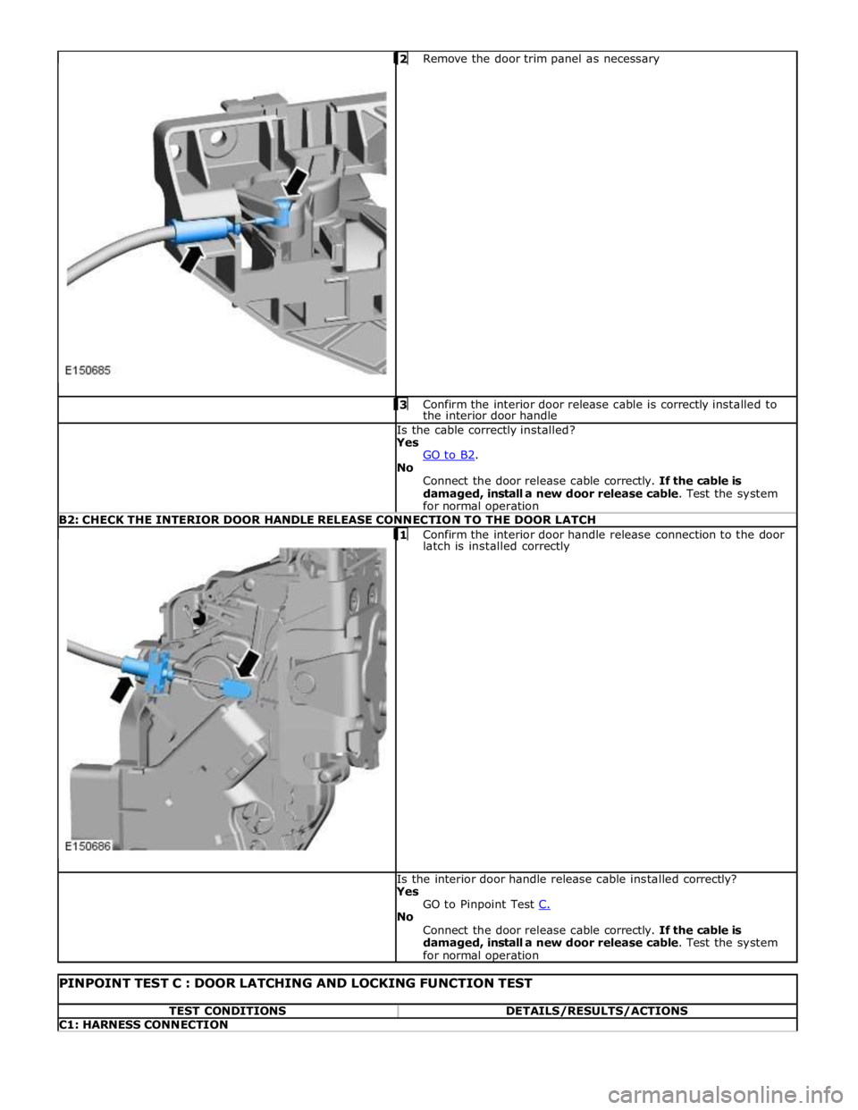
Remove the door trim panel as necessary 3 Confirm the interior door release cable is correctly installed to the interior door handle Is the cable correctly installed?
Yes
GO to B2. No
Connect the door release cable correctly. If the cable is
damaged, install a new door release cable. Test the system
for normal operation B2: CHECK THE INTERIOR DOOR HANDLE RELEASE CONNECTION TO THE DOOR LATCH
1 Confirm the interior door handle release connection to the door latch is installed correctly Is the interior door handle release cable installed correctly?
Yes
GO to Pinpoint Test C. No
Connect the door release cable correctly. If the cable is
damaged, install a new door release cable. Test the system
for normal operation
PINPOINT TEST C : DOOR LATCHING AND LOCKING FUNCTION TEST TEST CONDITIONS DETAILS/RESULTS/ACTIONS C1: HARNESS CONNECTION
Page 2504 of 3039
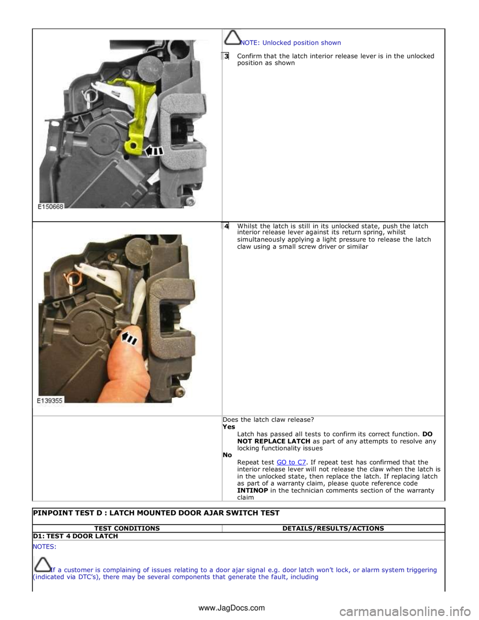
NOTE: Unlocked position shown 3 Confirm that the latch interior release lever is in the unlocked position as shown
4 Whilst the latch is still in its unlocked state, push the latch interior release lever against its return spring, whilst
simultaneously applying a light pressure to release the latch
claw using a small screw driver or similar Does the latch claw release? Yes
Latch has passed all tests to confirm its correct function. DO
NOT REPLACE LATCH as part of any attempts to resolve any
locking functionality issues
No
Repeat test GO to C7. If repeat test has confirmed that the interior release lever will not release the claw when the latch is
in the unlocked state, then replace the latch. If replacing latch
as part of a warranty claim, please quote reference code
INTINOP in the technician comments section of the warranty
claim
PINPOINT TEST D : LATCH MOUNTED DOOR AJAR SWITCH TEST TEST CONDITIONS DETAILS/RESULTS/ACTIONS D1: TEST 4 DOOR LATCH NOTES:
If a customer is complaining of issues relating to a door ajar signal e.g. door latch won’t lock, or alarm system triggering
(indicated via DTC’s), there may be several components that generate the fault, including www.JagDocs.com
Page 2543 of 3039
Wipers and Washers - Wipers and Washers
Diagnosis and Testing
Principle of Operation Published: 11-May-2011
For a detailed description of the wipers and washers, refer to the relevant Description and Operation sections in the workshop
manual. REFER to: (501-16 Wipers and Washers)
Wipers and Washers (Description and Operation), Wipers and Washers (Description and Operation), Wipers and Washers (Description and Operation).
Inspection and Verification
CAUTION: Diagnosis by substitution from a donor vehicle is NOT acceptable. Substitution of control modules does not
guarantee confirmation of a fault, and may also cause additional faults in the vehicle being tested and/or the donor vehicle.
1. Verify the customer concern.
2. Visually inspect for obvious signs of damage and system integrity.
Visual Inspection
Mechanical Electrical
Wiper blade(s)
Wiper pivot arm shaft
Washer reservoir
Hose(s)
Washer jet(s)
Fuse(s)
Wiring harness
Electrical connector(s)
Washer pump(s)
Wiper motor
3. If an obvious cause for an observed or reported concern is found, correct the cause (if possible) before proceeding to
the next step.
4. If the cause is not visually evident, check for Diagnostic Trouble Codes (DTCs) and refer to the DTC Index.
DTC Index
CAUTION: When probing connectors to take measurements in the course of the pinpoint tests, use the adaptor kit, part
number 3548-1358-00.
NOTES:
If the control module or a component is suspect and the vehicle remains under manufacturer warranty, refer to the
Warranty Policy and Procedures manual (section B1.2), or determine if any prior approval programme is in operation, prior to
the installation of a new module/component.
Generic scan tools may not read the codes listed, or may read only five digit codes. Match the five digits from the scan
tool to the first five digits of the seven digit code listed to identify the fault (the last two digits give additional information
read by the manufacturer approved diagnostic system).
When performing electrical voltage or resistance tests, always use a digital multimeter (DMM) accurate to three decimal
places, and with an up-to-date calibration certificate. When testing resistance, always take the resistance of the DMM leads
into account.
Check and rectify basic faults before beginning diagnostic routines involving pinpoint tests.
Inspect connectors for signs of water ingress, and pins for damage and/or corrosion.
If DTCs are recorded and, after performing the pinpoint tests, a fault is not present, an intermittent concern may be the
cause. Always check for loose connections and corroded terminals.
DTC Description Possible Cause Action B109512
Wiper On/Off
Relay
Wiper On/Off relay control Carry out any pinpoint tests associated with this DTC using the
manufacturer approved diagnostic system. Refer to the electrical
Page 2544 of 3039

DTC Description Possible Cause Action circuit - short to power
circuit diagrams and check wiper On/Off relay control circuit for
short to power B109514
Wiper On/Off
Relay
Wiper On/Off relay control
circuit - short to ground,
open circuit Refer to the electrical circuit diagrams and check wiper On/Off
relay control circuit for short to ground, open circuit B109612
Wiper High/Low
Relay
Wiper Fast/Slow relay
control circuit - short to
power Carry out any pinpoint tests associated with this DTC using the
manufacturer approved diagnostic system. Refer to the electrical
circuit diagrams and check wiper Fast/Slow relay control circuit for
short to power B109614
Wiper High/Low
Relay
Wiper Fast/Slow relay
control circuit - short to
ground, open circuit Refer to the electrical circuit diagrams and check wiper Fast/Slow
relay control circuit for short to ground, open circuit B10AD09 Rain Sensor
Component failures Carry out any pinpoint tests associated with this DTC using the
manufacturer approved diagnostic system. Suspect the rain/light
sensor, check and install a new sensor as required B10AD11 Rain Sensor
Rain/light sensor power
circuit - short to ground Carry out any pinpoint tests associated with this DTC using the
manufacturer approved diagnostic system. Refer to the electrical
circuit diagrams and check rain/light sensor power circuit for short
to ground B10AD96 Rain Sensor
Component internal
failure Suspect the rain/light sensor, check and install a new sensor as
required B117712
Screenwash
Level Switch
Screenwash level switch
signal circuit - short to
power Refer to the electrical circuit diagrams and check screenwash level
switch signal circuit for short to power B1C4513
Front Wiper Park
Position Switch
Windshield wiper motor
park switch signal circuit -
open circuit Refer to the electrical circuit diagrams and check windshield wiper
motor park switch signal circuit for open circuit B1C4523
Front Wiper Park
Position Switch
Signal stuck low Refer to the electrical circuit diagrams and check front wiper park
position switch input circuit for short, open circuit B1C7812 Powerwash Relay
Powerwash relay control
circuit - short to power Refer to the electrical circuit diagrams and check powerwash relay
control circuit for short to power B1C7814 Powerwash Relay
Powerwash relay control
circuit - short to ground,
open circuit Refer to the electrical circuit diagrams and check powerwash relay
control circuit for short to ground, open circuit B1C7911
Front Washer
Pump
Screenwash pump control
circuit - short to ground Refer to the electrical circuit diagrams and check screenwash
pump control circuit for short to ground B1C7913
Front Washer
Pump
Screenwash pump control
circuit - open circuit Carry out any pinpoint tests associated with this DTC using the
manufacturer approved diagnostic system. Refer to the electrical
circuit diagrams and check screenwash pump control circuit for open circuit www.JagDocs.com
Page 2563 of 3039
Roof Opening Panel - Roof Opening Panel
Diagnosis and Testing
Principle of Operation Published: 11-May-2011
For a detailed description of the roof opening panel, refer to the relevant Description and Operation sections in the workshop
manual. REFER to: (501-17 Roof Opening Panel)
Roof Opening Panel (Description and Operation), Roof Opening Panel (Description and Operation), Roof Opening Panel (Description and Operation).
Inspection and Verification
CAUTION: Diagnosis by substitution from a donor vehicle is NOT acceptable. Substitution of control modules does not
guarantee confirmation of a fault, and may also cause additional faults in the vehicle being tested and/or the donor vehicle.
1. Verify the customer concern.
2. Visually inspect for obvious signs of damage and system integrity.
Visual Inspection
Mechanical Electrical
Roof opening panel
Helixed drive cables
Switch
Control unit/motor
Fuses/relays (refer to electrical guide)
Wiring harness
Correct engagement of electrical connectors
Loose or corroded connections
3. If an obvious cause for an observed or reported concern is found, correct the cause (if possible) before proceeding to
the next step.
4. If the cause is not visually evident, check for Diagnostic Trouble Codes (DTCs) and refer to the DTC Index.
DTC Index
CAUTION: When probing connectors to take measurements in the course of the pinpoint tests, use the adaptor kit, part
number 3548-1358-00.
NOTES:
If the control module or a component is suspect and the vehicle remains under manufacturer warranty, refer to the
Warranty Policy and Procedures manual (section B1.2), or determine if any prior approval programme is in operation, prior to
the installation of a new module/component.
Generic scan tools may not read the codes listed, or may read only five digit codes. Match the five digits from the scan
tool to the first five digits of the seven digit code listed to identify the fault (the last two digits give extra information read by
the manufacturer-approved diagnostic system).
When performing voltage or resistance tests, always use a digital multimeter (DMM) accurate to three decimal places and
with a current calibration certificate. When testing resistance, always take the resistance of the DMM leads into account.
Check and rectify basic faults before beginning diagnostic routines involving pinpoint tests.
If DTCs are recorded and, after performing the pinpoint tests, a fault is not present, an intermittent concern may be the
cause. Always check for loose connections and corroded terminals.
DTC Description Possible Cause Action B10F211 Sunroof Control
Sunroof enable signal
circuit - short to ground Carry out any pinpoint tests associated with this DTC using the
manufacturer approved diagnostic system. Refer to the electrical
circuit diagrams and check sunroof enable signal circuit for short
to ground B10F212 Sunroof Control
Sunroof enable signal
circuit - short to power Refer to the electrical circuit diagrams and check sunroof enable
signal circuit for short to power