jacking JAGUAR XFR 2010 1.G Workshop Manual
[x] Cancel search | Manufacturer: JAGUAR, Model Year: 2010, Model line: XFR, Model: JAGUAR XFR 2010 1.GPages: 3039, PDF Size: 58.49 MB
Page 3 of 3039

Diagnostic Trouble Code (DTC) IndexDTC: Occupant Classification System (OCS)
Diagnostic Trouble Code (DTC) IndexDTC: Parking Aid Module (PAM)
Diagnostic Trouble Code (DTC) IndexDTC: Pedestrian Protection System Control Module (PPSCM)
Diagnostic Trouble Code (DTC) IndexDTC: Rear Differential Control Module (RDCM)
Diagnostic Trouble Code (DTC) IndexDTC: Rear Junction Box (RJB)
Diagnostic Trouble Code (DTC) IndexDTC: Remote Keyless Entry Module (RFA)
Diagnostic Trouble Code (DTC) IndexDTC: Restraints Control Module (RCM)
Diagnostic Trouble Code (DTC) IndexDTC: Satellite Digital Audio Radio System Module (SARM)
Diagnostic Trouble Code (DTC) IndexDTC: Speed Control Module (CCM)
Diagnostic Trouble Code (DTC) IndexDTC: Steering Column Lock Module (VIM)
Diagnostic Trouble Code (DTC) IndexDTC: Television Module (TVM)
Diagnostic Trouble Code (DTC) IndexDTC: Tire Pressure Monitoring System Module (TPM)
Diagnostic Trouble Code (DTC) IndexDTC: Touch Screen Display (FCDIM)
Diagnostic Trouble Code (DTC) IndexVehicles With: 6HP28 6-Speed Automatic Transmission, DTC:
Transmission Control Module (TCM)
Diagnostic Trouble Code (DTC) IndexDTC: Transmission Shift Module (GSM)
Diagnostic Trouble Code (DTC) IndexDTC: Portable Audio Interface Control Module (PAICM)
Diagnostic Trouble Code (DTC) IndexDTC: Hybrid Digital Radio Control Module (HDRCM)
Diagnostic Trouble Code (DTC) IndexDTC: Infotainment Control Module (ICM)
Diagnostic Trouble Code (DTC) IndexDTC: Telephone Module (TEL)100-01: Identification Codes
Description and OperationIdentification Codes100-02: Jacking and Lifting
Description and OperationJacking
Lifting100-04: Noise, Vibration and Harshness
Description and OperationNoise, Vibration and Harshness (NVH)Diagnosis and TestingNoise, Vibration and Harshness (NVH)General ProceduresExhaust System Neutralizing2: Chassis
204: Suspension
204-00: Suspension System - General InformationSpecificationDiagnosis and TestingSuspension SystemGeneral ProceduresCamber and Caster Adjustment
Page 67 of 3039
Do not empty fuel while working in a workshop or a pit
Ensure that working area is well ventilated
Ensure that any work on the fuel system is only carried out by experienced and well qualified maintenance personnel
Ensure that fume extraction equipment is used where appropriate
Fume extraction equipment must be in operation when solvents are used e.g. Trichloroethane, white spirit, sbp3,
methylene chloride, perchlorethylene. Do not smoke in the vicinity of volatile degreasing agents.
Whenever possible, use a ramp or pit whilst working beneath a vehicle, in preference to jacking. Position chocks at the wheels
as well as applying the parking brake. Never rely on a jack alone to support a vehicle. Use axle stands, or blocks carefully
placed at the jacking points, to provide a rigid location. Check that any lifting equipment used has adequate capacity and is
fully serviceable. Ensure that a suitable form of fire extinguisher is conveniently located. When using electrical tools and
equipment, inspect the power lead for damage and check that it is properly earthed. Disconnect the earth (grounded) terminal
of the vehicle battery. Do not disconnect any pipes of the air conditioning refrigeration system unless you are trained and
instructed to do so. A refrigerant is used which can cause blindness if allowed to come into contact with the eyes. Ensure that
adequate ventilation is provided when volatile degreasing agents are being used.
Adhere strictly to handling and safety instructions given on containers and labels. Keep oils and solvents away from naked
flames and other sources of ignition. Do not apply heat in an attempt to free seized nuts or fittings; as well as causing
damage to protective coatings, there is a risk of damage from stray heat to electronic equipment and brake lines. Do not leave
tools, equipment, spilt oil etc. around the work area. Wear protective overalls and use barrier cream when necessary.
Environmental Protection
In some countries it is illegal to pour used oil onto the ground, down sewers or drains, or into water courses. The burning of
used engine oil in small space heaters or boilers is not recommended unless emission control equipment is installed. Dispose
of used oil through authorized waste disposal contractors, to licensed waste disposal sites or to the waste oil reclamation
trade. If in doubt, contact the Local Authority for advice on disposal facilities.
Page 294 of 3039
Jacking and Lifting - Jacking
Description and Operation
Safety Precautions Published: 11-May-2011
WARNING: The jack provided with the vehicle is intended to be used in an emergency for changing a deflated tire. To
avoid damage to the vehicle, never use the jack to raise the vehicle for any other purpose. Refer to the Driver Handbook when
using the jack supplied with the vehicle. Failure to follow these instructions may result in personal injury.
The following safety precautions must be observed when raising the vehicle to carry out service operations:
Never rely on a jack alone to support a vehicle. Always use suitable vehicle stands to provide rigid support.
When working beneath a vehicle, whenever possible use a vehicle hoist instead of a jack and vehicle stands.
Make sure that the vehicle is standing on firm, level ground before using a jack.
Do not rely on the parking brake alone; chock the wheels and put the automatic transmission into Park if possible.
Check that any lifting equipment used has adequate capacity for the load being lifted and is in correct working order.
Page 295 of 3039
Jacking and Lifting - Lifting
Description and Operation
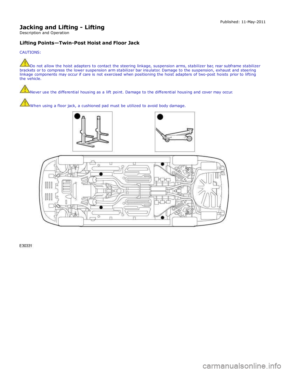
Lifting Points—Twin-Post Hoist and Floor Jack
CAUTIONS: Published: 11-May-2011
Do not allow the hoist adapters to contact the steering linkage, suspension arms, stabilizer bar, rear subframe stabilizer
brackets or to compress the lower suspension arm stabilizer bar insulator. Damage to the suspension, exhaust and steering
linkage components may occur if care is not exercised when positioning the hoist adapters of two-post hoists prior to lifting
the vehicle.
Never use the differential housing as a lift point. Damage to the differential housing and cover may occur.
When using a floor jack, a cushioned pad must be utilized to avoid body damage.
Page 302 of 3039
and drive half shaft failure, which could cause serious personal injury and extensive vehicle damage. Failure to follow these
instructions may result in personal injury.
CAUTION: The suspension should not be allowed to hang free. When the CV joint is run at a very high angle, extra
vibration as well as damage to the seals and joints can occur.
The rear suspension lower arm should be supported as far outboard as possible. To bring the vehicle to its correct ride height,
the full weight of the vehicle should be supported in the rear by floor jacks. REFER to: (100-02 Jacking and Lifting)
Jacking (Description and Operation), Lifting (Description and Operation).
1. Raise and support the vehicle. REFER to: (100-02 Jacking and Lifting)
Jacking (Description and Operation), Lifting (Description and Operation).
2. Explore the speed range of interest using the Road Test Quick Checks as previously described.
3. Carry out a coast down in neutral. If the vehicle is free of vibration when operating at a steady indicated speed and
behaves very differently in drive and coast, a transmission concern is likely.
Note, however, that a test on the lift may produce different vibrations and noises than a road test because of the effect of the
lift. It is not unusual to find vibrations on the lift that were not found in the road test. If the condition found on the road can
be duplicated on the lift, carrying out experiments on the lift may save a great deal of time.
Exhaust Neutralization Procedure
1. Raise vehicle on lift and slacken all exhaust fixings.
2. With all fixings loose, neutralize the exhaust system.
3. Tighten all fixings to correct torque, starting at the rear-most point working towards the front of the vehicle.
Symptom Chart
Symptom Possible Cause Action High-speed shake
Wheel end vibration
Engine/transmission
Driveline GO to Pinpoint Test A. Tip-in moan
Air cleaner
Power steering
Powertrain
Engine mounts
Exhaust system GO to Pinpoint Test B. Idle boom/shake/vibration, or shudder
Cable(s)/hoses(s)
Intake air distribution and filtering system
Engine mounts
Exhaust system
Belt/pulleys GO to Pinpoint Test C. Wheel end vibration analysis
Suspension/rear drive halfshaft and CV joints
Tires/wheels
Wheel bearings
CV joint boots GO to Pinpoint Test D. Non-axle noise
Trim/mouldings
A/C system
Accessories GO to Pinpoint Test E. Pinpoint Tests
NOTE: These Pinpoint Tests are designed to take the technician through a step-by-step diagnosis procedure to determine
the cause of a condition. It may not always be necessary to follow the chart to its conclusion. Carry out only the Pinpoint Test
steps necessary to correct the condition. Then check operation of the system to make sure the condition is corrected.
After verifying that the condition has been corrected, make sure all components removed have been installed.
PINPOINT TEST A : HIGH-SPEED SHAKE TEST DETAILS/RESULTS/ACTIONS www.JagDocs.com
Page 303 of 3039
PINPOINT TEST B : TIP-IN MOAN TEST
CONDITIONS DETAILS/RESULTS/ACTIONS B1: CHECK THE AIR CLEANER 1 Check the air cleaner.
Check the air cleaner, inlet tube, outlet tube, resonators and all other components associated with
the air induction system for correct installation and tightness of all connections. Are the components OK? Yes
GO to B2. No
Correct the condition. Repeat the Road Test as outlined. B2: CHECK THE EXHAUST SYSTEM 1 Carry out the exhaust system neutralizing procedure in this section. Is the exhaust system OK? Yes
GO to B3. No
Repair as necessary. Restore vehicle. Repeat the Road Test as outlined. B3: CHECK THE POWER STEERING 1 Remove the auxiliary drive belt and test for tip-in moan. Is the tip-in moan OK? Yes
Repair the power steering as necessary. For additional information, refer to Section 211-00.
No
Check and install new engine/transmission mounts as necessary. Repeat Road Test as outlined.
PINPOINT TEST C : IDLE BOOM/SHAKE/VIBRATION/SHUDDER TEST
CONDITIONS DETAILS/RESULTS/ACTIONS C1: CHECK CABLE/HOSES 1 Check the engine compartment for any component that may be grounding between the engine and body or chassis. Example: air conditioning (A/C) hoses. Are the components OK? Yes
GO to C2. No
Correct the condition. Repeat the Road Test as outlined. C2: CHECK THE COOLING RADIATOR 1 Check the engine cooling radiator mountings and bushings for security and condition. Check the radiator installation for any component that may have a touch condition. Are the installation and bushings OK? Yes
GO to C3. No
Correct the condition. Repeat the Road Test as outlined. C3: CHECK THE EXHAUST SYSTEM 1 Carry out the exhaust system neutralizing procedure in this section. Is the exhaust system OK? Yes
Check and install new engine/transmission mounts as necessary. Repeat Road Test as outlined.
No
Repair as necessary. Repeat Road Test.
PINPOINT TEST D : WHEEL END VIBRATION ANALYSIS TEST CONDITIONS DETAILS/RESULTS/ACTIONS D1: INSPECT THE TIRES 1 Inspect the tires.
Raise and support the vehicle. REFER to: (100-02 Jacking and Lifting)
Jacking (Description and Operation), Lifting (Description and Operation).
Inspect the tires for:
Correct tire size
Tire/wheel compatibility
Wear or damage
Page 304 of 3039
Tire beads correctly seated Are the tires OK? Yes
GO to D2. No
Inspect the wheels. For additional information, refer to Section 204-00. D2: INSPECT WHEEL BEARINGS 1 Inspect the wheel bearings. For additional information, refer to Section 204-00. Are the wheel bearings OK? Yes
GO to D3. No
Repair as necessary. Repeat the Road Test as outlined. D3: INSPECT THE CONSTANT VELOCITY (CV) JOINT BOOTS 1 Inspect the CV joint boots. Spin the rear tire by hand
Inspect for evidence of cracks, tears, splits or splattered grease Are the CV joint boots OK? Yes
GO to D4. No
Repair as necessary. Repeat the Road Test as outlined. D4: INSPECT WHEEL AND TIRE RUNOUT 1 Inspect the wheel and tire runout. Carry out the Wheel and Tire Check procedure.
REFER to: Lifting (100-02 Jacking and Lifting, Description and Operation). Is the wheel and tire runout OK? Yes
Balance the wheels and tires. Refer to the wheel balance equipment manufacturers instructions.
No
Repair as necessary.
REFER to: Lifting (100-02 Jacking and Lifting, Description and Operation). Repeat the Road Test as outlined.
PINPOINT TEST E : NON-AXLE NOISE TEST
CONDITIONS DETAILS/RESULTS/ACTIONS E1: INSPECT VEHICLE TRIM 1 Check the grille and trim mouldings to see if they are the source of the noise. Are the vehicle trim components causing the noise? Yes
Install new trim or repair as necessary. For additional information, refer to Section 501-08.
No
GO to E2. E2: CHECK THE A/C SYSTEM FOR NOISE 1 Check the A/C system components for noise by turning the A/C system on and off. Is the A/C system causing the noise? Yes
Diagnose the A/C system.
REFER to: Lifting (100-02 Jacking and Lifting, Description and Operation). No
GO to E3. E3: CHECK NON-FACTORY ACCESSORIES 1 Inspect any accessories for being the source of the noise. Example: grounding body-to-frame, antennas, visors, bug deflectors and fog lights? Are the accessories the cause of the noise? Yes
Adjust, repair or install new accessories or fasteners as required.
No
Verify the customer concern.
Page 310 of 3039
Shock Absorber and Spring Assembly (204-02 Rear Suspension, Removal and Installation). * Loose front stabilizer bar or rear
stabilizer bar. * Check and tighten the stabilizer bar to specification.
REFER to:
Specifications (204-01 Front Suspension, Specifications), Specifications (204-02 Rear Suspension, Specifications). * Worn lower suspension arm stabilizer
bar insulators. * Install new lower suspension arm stabilizer bar as
necessary. REFER to:
Front Stabilizer Bar - 2.7L Diesel (204-01, Removal and
Installation),
Front Stabilizer Bar - V6 3.0L Petrol (204-01 Front Suspension, Removal and Installation),
Front Stabilizer Bar - 4.2L (204-01, Removal and
Installation),
Rear Stabilizer Bar (204-02 Rear Suspension, Removal and Installation). * Shock absorber(s). * Check and install new shock absorber(s) as necessary.
REFER to:
Front Shock Absorber (204-01 Front Suspension, Removal and Installation),
Shock Absorber and Spring Assembly (204-02 Rear Suspension, Removal and Installation). Vehicle Leans to One
Side * Unevenly loaded or overloaded vehicle. * Notify the customer of incorrect vehicle loading. * Front or rear suspension components.
* Inspect the front and rear suspension systems. Repair or
install new suspension components as necessary. * Shock absorber(s). * Check and install new shock absorber(s) as necessary.
REFER to:
Front Shock Absorber (204-01 Front Suspension, Removal and Installation),
Shock Absorber and Spring Assembly (204-02 Rear Suspension, Removal and Installation). * Coil spring(s).
* Check and install new spring(s) as necessary. REFER to:
Front Shock Absorber (204-01 Front Suspension, Removal and Installation),
Shock Absorber and Spring Assembly (204-02 Rear Suspension, Removal and Installation). * Incorrect ride height. Lateral tilt out of
specification. * Check the ride height. Install new spring(s) as
necessary. REFER to:
Front Shock Absorber (204-01 Front Suspension, Removal and Installation),
Shock Absorber and Spring Assembly (204-02 Rear Suspension, Removal and Installation). Vibration/Noise * Tires/wheels.
* Wheel bearings.
* Wheel hubs.
* Brake components.
* Suspension components.
* Steering components. * Check and install new components as necessary. Wander * Unevenly loaded or overloaded vehicle. * Notify the customer of incorrect vehicle loading. * Ball joint(s). * Check the Ball Joint(s). * Front wheel bearing(s). * Check the wheel bearings. * Loose, worn or damaged suspension components. * Check and install new suspension components as necessary. * Loose suspension fasteners.
* Check and tighten the suspension fasteners to
specification.
REFER to: Specifications (204-00 Suspension System - General Information, Specifications). * Steering components. * Check and install new steering components. * Wheel alignment (excessive total front
toe-out). * Check and adjust the wheel alignment. REFER to:
(204-00 Suspension System - General Information)
Front Toe Adjustment (General Procedures), Rear Toe Adjustment (General Procedures), Camber and Caster Adjustment (General Procedures). Component Tests
Ball Joint Inspection
NOTE: The front suspension is shown in the following procedures. The inspection of the rear suspension upper ball joint
is similar.
1. Raise and support the vehicle. REFER to: (100-02 Jacking and Lifting)
Jacking (Description and Operation), Lifting (Description and Operation).
2. Prior to carrying out any inspection of the ball joints, inspect the front wheel bearings.
Page 2121 of 3039
Anti-Theft - Active - Anti-Theft - Active - Overview
Description and Operation
Overview Published: 11-May-2011
The active anti-theft system is available with three different levels of vehicle protection depending on market specification:
Hinged panel sensing
Hinged panel and intrusion sensing
Hinged panel, intrusion and inclination sensing.
The CJB (central junction box) automatically arms and disarms the active anti-theft system when it functions the central
locking system.
Refer to: Handles, Locks, Latches and Entry Systems (501-14 Handles, Locks, Latches and Entry Systems, Description and Operation).
Depending on market specification two modes of protection are used: perimeter mode and volumetric mode.
Perimeter mode
Perimeter mode, monitors the security of the hinged panels, which include:
all doors,
luggage compartment lid, and
engine compartment lid.
When perimeter mode is active, the CJB monitors the panel ajar switches in the latch mechanisms of the hinged panels.
Volumetric mode
In volumetric mode the CJB monitors the interior of the vehicle for movement using an ultrasonic sound wave sensor.
If the battery backed sounder incorporates an inclination sensor the vehicle will also be monitored for unauthorised tilting; for
example towing or jacking.