pinpoint JAGUAR XFR 2010 1.G Workshop Manual
[x] Cancel search | Manufacturer: JAGUAR, Model Year: 2010, Model line: XFR, Model: JAGUAR XFR 2010 1.GPages: 3039, PDF Size: 58.49 MB
Page 2564 of 3039

DTC Description Possible Cause Action B10F213 Sunroof Control
Sunroof enable signal
circuit - open circuit Refer to the electrical circuit diagrams and check sunroof enable
signal circuit for open circuit B113D12
Sunroof Global
Open/Close
Control
Roof opening panel global
open/close control circuit -
short to power Carry out any pinpoint tests associated with this DTC using the
manufacturer approved diagnostic system. Refer to the electrical
circuit diagrams and check roof opening panel global open/close
control circuit for short to power B113D14
Sunroof Global
Open/Close
Control
Roof opening panel global
open/close control circuit -
short to ground, open
circuit Refer to the electrical circuit diagrams and check roof opening
panel global open/close control circuit for short to ground, open
circuit www.JagDocs.com
Page 2595 of 3039

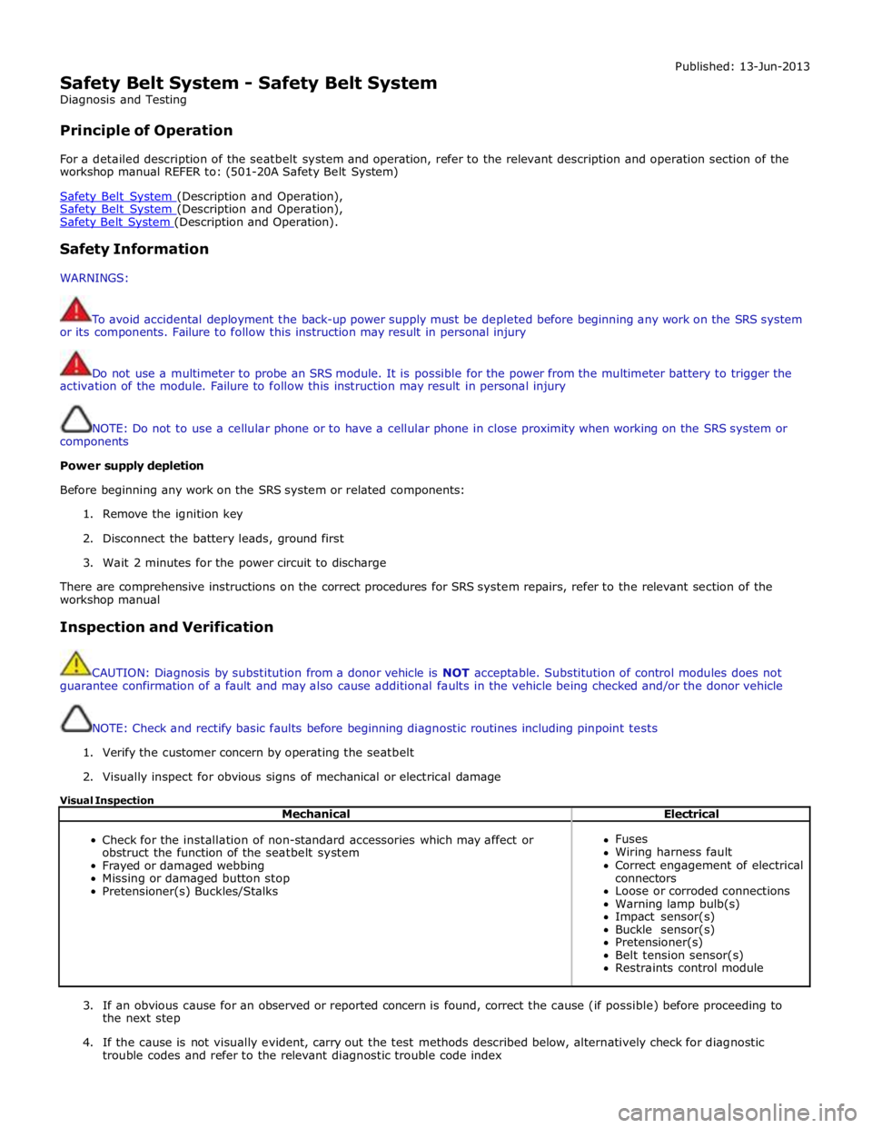
Safety Belt System - Safety Belt System
Diagnosis and Testing
Principle of Operation Published: 13-Jun-2013
For a detailed description of the seatbelt system and operation, refer to the relevant description and operation section of the
workshop manual REFER to: (501-20A Safety Belt System)
Safety Belt System (Description and Operation), Safety Belt System (Description and Operation), Safety Belt System (Description and Operation).
Safety Information
WARNINGS:
To avoid accidental deployment the back-up power supply must be depleted before beginning any work on the SRS system
or its components. Failure to follow this instruction may result in personal injury
Do not use a multimeter to probe an SRS module. It is possible for the power from the multimeter battery to trigger the
activation of the module. Failure to follow this instruction may result in personal injury
NOTE: Do not to use a cellular phone or to have a cellular phone in close proximity when working on the SRS system or
components
Power supply depletion
Before beginning any work on the SRS system or related components:
1. Remove the ignition key
2. Disconnect the battery leads, ground first
3. Wait 2 minutes for the power circuit to discharge
There are comprehensive instructions on the correct procedures for SRS system repairs, refer to the relevant section of the
workshop manual
Inspection and Verification
CAUTION: Diagnosis by substitution from a donor vehicle is NOT acceptable. Substitution of control modules does not
guarantee confirmation of a fault and may also cause additional faults in the vehicle being checked and/or the donor vehicle
NOTE: Check and rectify basic faults before beginning diagnostic routines including pinpoint tests
1. Verify the customer concern by operating the seatbelt
2. Visually inspect for obvious signs of mechanical or electrical damage
Visual Inspection
Mechanical Electrical
Check for the installation of non-standard accessories which may affect or
obstruct the function of the seatbelt system
Frayed or damaged webbing
Missing or damaged button stop
Pretensioner(s) Buckles/Stalks
Fuses
Wiring harness fault
Correct engagement of electrical
connectors
Loose or corroded connections
Warning lamp bulb(s)
Impact sensor(s)
Buckle sensor(s)
Pretensioner(s)
Belt tension sensor(s)
Restraints control module
3. If an obvious cause for an observed or reported concern is found, correct the cause (if possible) before proceeding to
the next step
4. If the cause is not visually evident, carry out the test methods described below, alternatively check for diagnostic
trouble codes and refer to the relevant diagnostic trouble code index
Page 2596 of 3039

For a complete list of all diagnostic trouble codes that could be logged on this vehicle, please refer to section 100-00.
REFER to: Supplemental Restraint System (SRS) Health and Safety Precautions (100-00 General Information, Description and Operation) /
Diagnostic Trouble Code (DTC) Index - DTC: Restraints Control Module (RCM) (100-00, Description and Operation).
Symptom Chart for Seatbelt Rows 1, 2
Symptom Possible Causes Action Seatbelt jammed -
Webbing tight
Backlock effect in action (webbing retracted
quickly and came to sudden stop)
Seatbelt retractor not installed correctly
Automatic locking retractor activated (clicking
– during retraction only)
GO to Pinpoint Test A. GO to Pinpoint Test F. See the automatic locking retractor
description below Seatbelt jammed -
Seatbelt webbing trapped in seat
GO to Pinpoint Test B. Webbing loose Seatbelt retractor webbing guide loose GO to Pinpoint Test C. Twist in webbing GO to Pinpoint Test D. Interference in webbing routing GO to Pinpoint Test E. D-loop not rotating correctly GO to Pinpoint Test G. Seatbelt - Intermittent jamming
Seatbelt retractor not installed correctly
GO to Pinpoint Test F. Seatbelt - Slow retraction
Seatbelt retractor webbing guide loose
GO to Pinpoint Test C. Twist in seatbelt webbing GO to Pinpoint Test D. Interference in webbing routing GO to Pinpoint Test E. Seatbelt retractor not installed correctly GO to Pinpoint Test F. D-loop not rotating correctly GO to Pinpoint Test G. Foreign object/debris GO to Pinpoint Test E. Seatbelt - Not retracting
Seatbelt retractor webbing guide loose
GO to Pinpoint Test C. Twist in seatbelt webbing GO to Pinpoint Test D. D-loop not rotating correctly GO to Pinpoint Test G. Interference in webbing routing GO to Pinpoint Test E. Foreign object/debris GO to Pinpoint Test E. Seatbelt - Not extracting
Backlock effect-in action (webbing retracted
GO to Pinpoint Test A. quickly and came to sudden stop) GO to Pinpoint Test F. Seatbelt retractor not installed correctly GO to Pinpoint Test C. Seatbelt retractor webbing guide loose GO to Pinpoint Test D. Twist in seatbelt webbing GO to Pinpoint Test G. D-loop not rotating correctly GO to Pinpoint Test E. Interference in webbing routing GO to Pinpoint Test E. Foreign object/debris See the automatic locking retractor Automatic locking retractor activated (clicking description below – during retraction only) Seatbelt - Noisy during
operation
Automatic locking retractor activated (clicking–
during retraction only)
Interference in webbing routing (rubbing)
GO to Pinpoint Test B. GO to Pinpoint Test E. Seatbelt buckle - Not
latching / jammed
Foreign object/debris
CAUTION: Do not insert any objects or
tools into the buckle head
GO to Pinpoint Test H.
Inertia Reel Seatbelts
The vehicle is equipped with (two row one) and (three row two) inertia reel seatbelts
These seatbelts are "dual sensitive" which means that they have:
Car sense system - A vehicle motion sensor, which locks the seatbelt webbing under braking, cornering, on steep
hills and in adverse camber conditions, when parked on a steep incline or driveway or two wheels on a high curb
Web sense system - A webbing motion sensor, which locks when the seatbelt webbing is extracted suddenly
The seatbelts in the following positions are equipped with an automatic locking retractor function:
Page 2597 of 3039

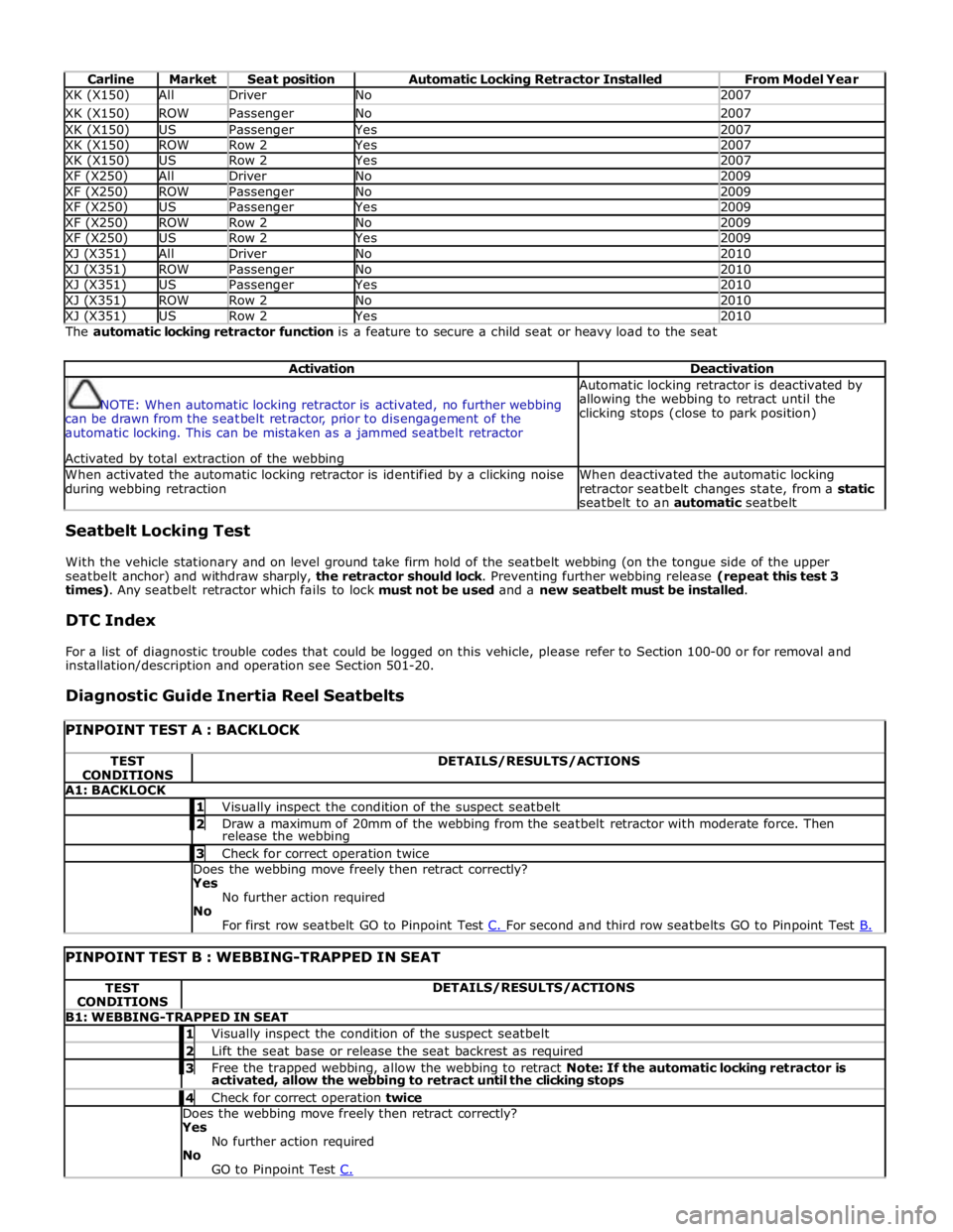
Carline Market Seat position Automatic Locking Retractor Installed From Model Year XK (X150) All Driver No 2007 XK (X150) ROW Passenger No 2007 XK (X150) US Passenger Yes 2007 XK (X150) ROW Row 2 Yes 2007 XK (X150) US Row 2 Yes 2007 XF (X250) All Driver No 2009 XF (X250) ROW Passenger No 2009 XF (X250) US Passenger Yes 2009 XF (X250) ROW Row 2 No 2009 XF (X250) US Row 2 Yes 2009 XJ (X351) All Driver No 2010 XJ (X351) ROW Passenger No 2010 XJ (X351) US Passenger Yes 2010 XJ (X351) ROW Row 2 No 2010 XJ (X351) US Row 2 Yes 2010 The automatic locking retractor function is a feature to secure a child seat or heavy load to the seat
Activation Deactivation
NOTE: When automatic locking retractor is activated, no further webbing
can be drawn from the seatbelt retractor, prior to disengagement of the
automatic locking. This can be mistaken as a jammed seatbelt retractor
Activated by total extraction of the webbing Automatic locking retractor is deactivated by
allowing the webbing to retract until the
clicking stops (close to park position) When activated the automatic locking retractor is identified by a clicking noise
during webbing retraction When deactivated the automatic locking
retractor seatbelt changes state, from a static
seatbelt to an automatic seatbelt Seatbelt Locking Test
With the vehicle stationary and on level ground take firm hold of the seatbelt webbing (on the tongue side of the upper
seatbelt anchor) and withdraw sharply, the retractor should lock. Preventing further webbing release (repeat this test 3
times). Any seatbelt retractor which fails to lock must not be used and a new seatbelt must be installed.
DTC Index
For a list of diagnostic trouble codes that could be logged on this vehicle, please refer to Section 100-00 or for removal and
installation/description and operation see Section 501-20.
Diagnostic Guide Inertia Reel Seatbelts
PINPOINT TEST A : BACKLOCK TEST
CONDITIONS DETAILS/RESULTS/ACTIONS A1: BACKLOCK 1 Visually inspect the condition of the suspect seatbelt 2 Draw a maximum of 20mm of the webbing from the seatbelt retractor with moderate force. Then release the webbing 3 Check for correct operation twice Does the webbing move freely then retract correctly?
Yes
No further action required
No
For first row seatbelt GO to Pinpoint Test C. For second and third row seatbelts GO to Pinpoint Test B.
PINPOINT TEST B : WEBBING-TRAPPED IN SEAT TEST
CONDITIONS DETAILS/RESULTS/ACTIONS B1: WEBBING-TRAPPED IN SEAT 1 Visually inspect the condition of the suspect seatbelt 2 Lift the seat base or release the seat backrest as required 3 Free the trapped webbing, allow the webbing to retract Note: If the automatic locking retractor is activated, allow the webbing to retract until the clicking stops 4 Check for correct operation twice Does the webbing move freely then retract correctly?
Yes
No further action required
No
GO to Pinpoint Test C.
Page 2598 of 3039

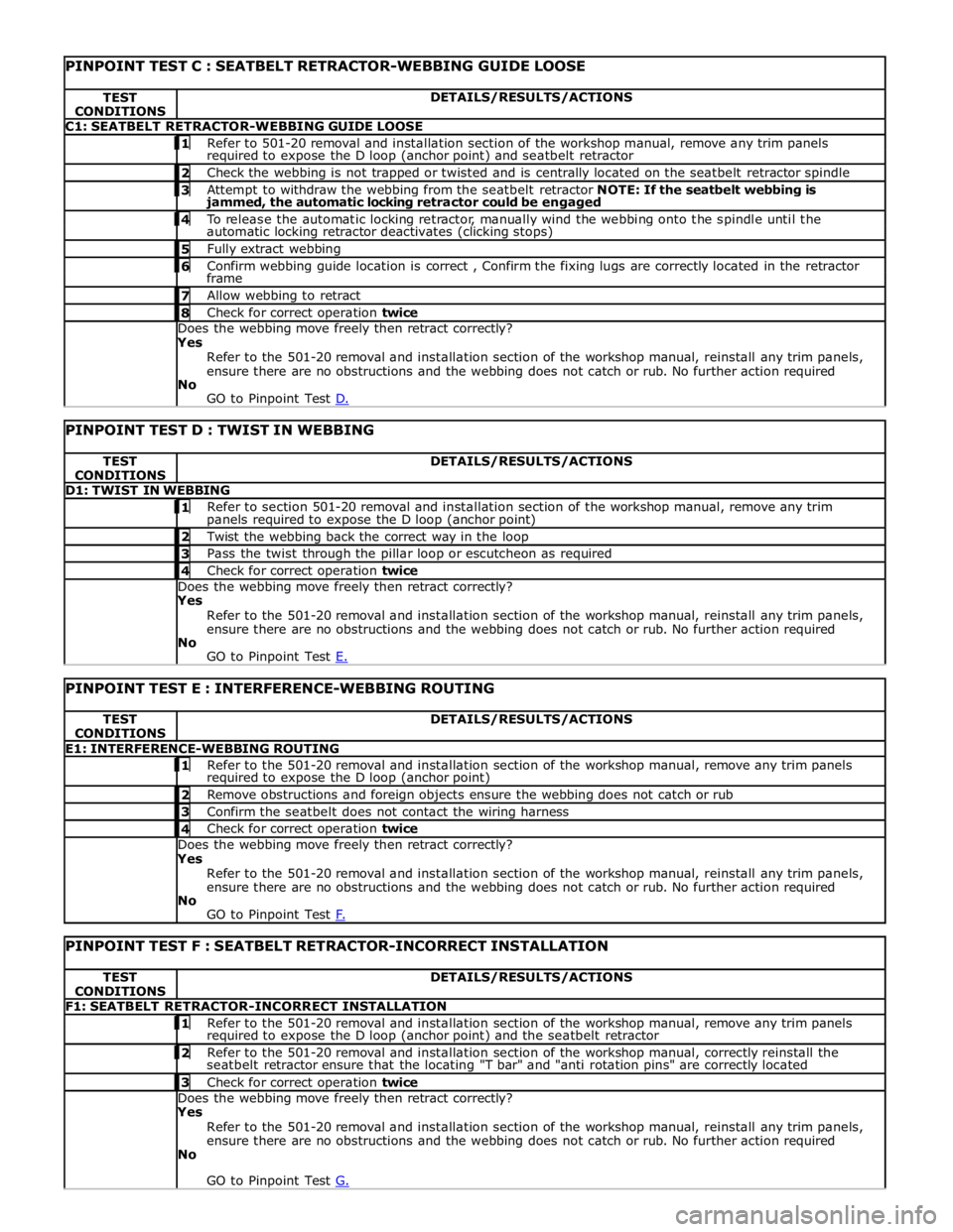
TEST
CONDITIONS DETAILS/RESULTS/ACTIONS C1: SEATBELT RETRACTOR-WEBBING GUIDE LOOSE 1 Refer to 501-20 removal and installation section of the workshop manual, remove any trim panels required to expose the D loop (anchor point) and seatbelt retractor 2 Check the webbing is not trapped or twisted and is centrally located on the seatbelt retractor spindle 3 Attempt to withdraw the webbing from the seatbelt retractor NOTE: If the seatbelt webbing is jammed, the automatic locking retractor could be engaged 4 To release the automatic locking retractor, manually wind the webbing onto the spindle until the automatic locking retractor deactivates (clicking stops) 5 Fully extract webbing 6 Confirm webbing guide location is correct , Confirm the fixing lugs are correctly located in the retractor frame 7 Allow webbing to retract 8 Check for correct operation twice Does the webbing move freely then retract correctly?
Yes
Refer to the 501-20 removal and installation section of the workshop manual, reinstall any trim panels,
ensure there are no obstructions and the webbing does not catch or rub. No further action required
No
GO to Pinpoint Test D.
PINPOINT TEST D : TWIST IN WEBBING TEST
CONDITIONS DETAILS/RESULTS/ACTIONS D1: TWIST IN WEBBING 1 Refer to section 501-20 removal and installation section of the workshop manual, remove any trim panels required to expose the D loop (anchor point) 2 Twist the webbing back the correct way in the loop 3 Pass the twist through the pillar loop or escutcheon as required 4 Check for correct operation twice Does the webbing move freely then retract correctly?
Yes
Refer to the 501-20 removal and installation section of the workshop manual, reinstall any trim panels,
ensure there are no obstructions and the webbing does not catch or rub. No further action required
No
GO to Pinpoint Test E.
PINPOINT TEST E : INTERFERENCE-WEBBING ROUTING TEST
CONDITIONS DETAILS/RESULTS/ACTIONS E1: INTERFERENCE-WEBBING ROUTING 1 Refer to the 501-20 removal and installation section of the workshop manual, remove any trim panels required to expose the D loop (anchor point) 2 Remove obstructions and foreign objects ensure the webbing does not catch or rub 3 Confirm the seatbelt does not contact the wiring harness 4 Check for correct operation twice Does the webbing move freely then retract correctly?
Yes
Refer to the 501-20 removal and installation section of the workshop manual, reinstall any trim panels,
ensure there are no obstructions and the webbing does not catch or rub. No further action required
No
GO to Pinpoint Test F.
PINPOINT TEST F : SEATBELT RETRACTOR-INCORRECT INSTALLATION TEST
CONDITIONS DETAILS/RESULTS/ACTIONS F1: SEATBELT RETRACTOR-INCORRECT INSTALLATION 1 Refer to the 501-20 removal and installation section of the workshop manual, remove any trim panels required to expose the D loop (anchor point) and the seatbelt retractor 2 Refer to the 501-20 removal and installation section of the workshop manual, correctly reinstall the seatbelt retractor ensure that the locating "T bar" and "anti rotation pins" are correctly located 3 Check for correct operation twice Does the webbing move freely then retract correctly?
Yes
Refer to the 501-20 removal and installation section of the workshop manual, reinstall any trim panels,
ensure there are no obstructions and the webbing does not catch or rub. No further action required
No
GO to Pinpoint Test G.
Page 2599 of 3039

PINPOINT TEST G : D-LOOP NOT ROTATING CORRECTLY TEST
CONDITIONS DETAILS/RESULTS/ACTIONS G1: D-LOOP NOT ROTATING CORRECTLY 1 Refer to the 501-20 removal and installation section of the workshop manual, remove any trim panels required to expose the D loop (anchor point) and the seatbelt retractor 2 Ensure there are no obstructions and the webbing does not catch or rub, the D loop (anchor point) rotates correctly and if installed the confirm the height adjuster operates correctly 3 Check for correct operation twice Does the webbing move freely then retract correctly? Yes
Refer to the 501-20 removal and installation section of the workshop manual, reinstall any trim panels,
ensure there are no obstructions and the webbing does not catch or rub. No further action required
No
Replace as required. Refer to the warranty policy and procedures manual, or determine if any prior approval programme is in operation, prior to the installation of a new module/component
PINPOINT TEST H : SEATBELT BUCKLE – NOT LATCHING/JAMMED TEST
CONDITIONS DETAILS/RESULTS/ACTIONS H1: SEATBELT BUCKLE – NOT LATCHING/JAMMED
CAUTION: Do not insert any objects or tools into the buckle head 1 Visually inspect the buckle head for evidence of damage. If damaged replace as required 2 Depress the buckle release (red button) and (Using a torch) carry out visual inspection for any evidence of debris/material or foreign objects in the buckle head 3 If required remove the pretensioner from the vehicle. Remove the seat. Remove the pretensioner from the seat frame 4 Do not insert any objects or tools buckle head With the buckle removed invert and attempt to shake out any debris 5 Attempt to latch the tongue in the buckle Does the seat belt buckle operate correctly Yes
Reinstall any components, no further action required
No
Replace the pretensioner, REFER to:
Diagnostic Trouble Code (DTC) Index - DTC: Restraints Control Module (RCM) (100-00 General
Information, Description and Operation),
Rear Safety Belt Buckle (501-20A Safety Belt System, Removal and Installation). www.JagDocs.com
Page 2687 of 3039

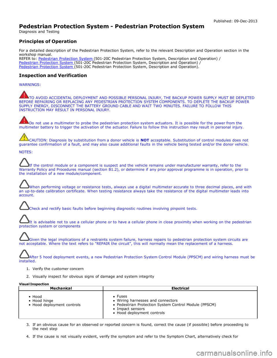
Pedestrian Protection System - Pedestrian Protection System
Diagnosis and Testing
Principles of Operation Published: 09-Dec-2013
For a detailed description of the Pedestrian Protection System, refer to the relevant Description and Operation section in the
workshop manual.
REFER to: Pedestrian Protection System (501-20C Pedestrian Protection System, Description and Operation) / Pedestrian Protection System (501-20C Pedestrian Protection System, Description and Operation) / Pedestrian Protection System (501-20C Pedestrian Protection System, Description and Operation).
Inspection and Verification
WARNINGS:
TO AVOID ACCIDENTAL DEPLOYMENT AND POSSIBLE PERSONAL INJURY, THE BACKUP POWER SUPPLY MUST BE DEPLETED
BEFORE REPAIRING OR REPLACING ANY PEDESTRIAN PROTECTION SYSTEM COMPONENTS. TO DEPLETE THE BACKUP POWER
SUPPLY ENERGY, DISCONNECT THE BATTERY GROUND CABLE AND WAIT TWO MINUTES. FAILURE TO FOLLOW THIS
INSTRUCTION MAY RESULT IN PERSONAL INJURY.
Do not use a multimeter to probe the pedestrian protection system actuators. It is possible for the power from the
multimeter battery to trigger the activation of the actuator. Failure to follow this instruction may result in personal injury.
CAUTION: Diagnosis by substitution from a donor vehicle is NOT acceptable. Substitution of control modules does not
guarantee confirmation of a fault, and may also cause additional faults in the vehicle being tested and/or the donor vehicle.
NOTES:
If the control module or a component is suspect and the vehicle remains under manufacturer warranty, refer to the
Warranty Policy and Procedures manual (section B1.2), or determine if any prior approval programme is in operation, prior to
the installation of a new module/component.
When performing voltage or resistance tests, always use a digital multimeter accurate to three decimal places, and with
an up-to-date calibration certificate. When testing resistance always take the resistance of the digital multimeter leads into
account.
Check and rectify basic faults before beginning diagnostic routines involving pinpoint tests.
It is advisable not to use a cellular phone or to have a cellular phone in close proximity when working on the pedestrian
protection system or components
Given the legal implications of a restraints system failure, harness repairs to pedestrian protection system circuits are
not acceptable. Where the text refers to "REPAIR the circuit", this will normally mean the replacement of a harness.
After 5 hood deployment events, a new Pedestrian Protection System Control Module (PPSCM) and wiring harness must be
installed.
1. Verify the customer concern
2. Visually inspect for obvious signs of damage and system integrity
Visual Inspection
Mechanical Electrical
Hood
Hood hinge
Hood deployment controls
Fuses
Wiring harnesses and connectors
Pedestrian Protection System Control Module (PPSCM)
Impact sensors
Hood deployment controls
3. If an obvious cause for an observed or reported concern is found, correct the cause (if possible) before proceeding to
the next step
4. If the cause is not visually evident, verify the symptom and refer to the Symptom Chart, alternatively check for