Actuator JAGUAR XFR 2010 1.G Owner's Manual
[x] Cancel search | Manufacturer: JAGUAR, Model Year: 2010, Model line: XFR, Model: JAGUAR XFR 2010 1.GPages: 3039, PDF Size: 58.49 MB
Page 255 of 3039

DTC Description Possible Causes Action P0613-13 TCM Processor - Circuit
Open
Watchdog fault
Suspect the Transmission Control Module. Install a
new Transmission Control Module as required,
refer to the warranty policy and procedures manual
if a module/component is suspect. P0613-14 TCM Processor - Circuit
Short to Ground or Open
Watchdog fault
Suspect the Transmission Control Module. Install a
new Transmission Control Module as required,
refer to the warranty policy and procedures manual
if a module/component is suspect. P0613-21 TCM Processor - Signal
amplitude < minimum
Watchdog fault
Suspect the Transmission Control Module. Install a
new Transmission Control Module as required,
refer to the warranty policy and procedures manual
if a module/component is suspect. P0613-22 TCM Processor - Signal
amplitude > maximum
Watchdog fault
Suspect the Transmission Control Module. Install a
new Transmission Control Module as required,
refer to the warranty policy and procedures manual
if a module/component is suspect. P0613-47 TCM Processor -
Watchdog / safety Micro
controller failure
Watchdog fault
Suspect the Transmission Control Module. Install a
new Transmission Control Module as required,
refer to the warranty policy and procedures manual
if a module/component is suspect. P0613-49 TCM Processor - Internal
electronic failure
Micro controller
component faults
Suspect the Transmission Control Module. Install a
new Transmission Control Module as required,
refer to the warranty policy and procedures manual
if a module/component is suspect. P0613-68 TCM Processor - Event
Information
Watchdog fault
Suspect the Transmission Control Module. Install a
new Transmission Control Module as required,
refer to the warranty policy and procedures manual
if a module/component is suspect. P061B-02
Internal Control Module Torque Calculation
Performance - General
signal failure
Transmission Control
Module - positive torque
signal not valid
Suspect the Transmission Control Module. Install a
new Transmission Control Module as required,
refer to the warranty policy and procedures manual
if a module/component is suspect. P061B-26
Internal Control Module Torque Calculation
Performance - Signal rate
of change below
threshold
Transmission Control
Module positive torque
signal not valid
Suspect the Transmission Control Module. Install a
new Transmission Control Module as required,
refer to the warranty policy and procedures manual
if a module/component is suspect. P062F-04
Internal Control Module
EEPROM Error - System
Internal Failures
EEPROM communication
error
Suspect the Transmission Control Module. Install a
new Transmission Control Module as required,
refer to the warranty policy and procedures manual
if a module/component is suspect. P0642-21
Sensor Reference Voltage
A Circuit Low - Signal
amplitude < minimum
Sensor supply voltage
fault low
Suspect the Transmission Control Module. Install a
new Transmission Control Module as required,
refer to the warranty policy and procedures manual
if a module/component is suspect. P0643-22
Sensor Reference Voltage
A Circuit High - Signal
amplitude > maximum
Sensor supply voltage
fault high
Suspect the Transmission Control Module. Install a
new Transmission Control Module as required,
refer to the warranty policy and procedures manual
if a module/component is suspect. P0657-13
Actuator Supply Voltage
A Circuit / Open - Circuit
Open
Actuator supply (pressure
control valves etc) Open
Circuit
Suspect the Transmission Control Module. Install a
new Transmission Control Module as required,
refer to the warranty policy and procedures manual
if a module/component is suspect. www.JagDocs.com
Page 256 of 3039

DTC Description Possible Causes Action P0657-1C
Actuator Supply Voltage
A Circuit / Open - Circuit
voltage out of range
Actuator supply (pressure
control valves etc)
voltage plausibility fault
Refer to electrical Circuit diagrams and check
Transmission Control Module connector for signs of
water ingress or damage, check pin 7 for Short to
Power or Ground (should NOT be connected and
harness terminal should have a bung installed). If
no fault identified, suspect the Transmission
Control Module. Check and install a new
Transmission Control Module as required, refer to
the warranty policy and procedures manual if a
module/component is suspect. P0658-11
Actuator Supply Voltage
A Circuit Low - Circuit
Short to Ground
Actuator supply (pressure
control valves etc)
voltage Short to Ground
Suspect the Transmission Control Module. Install a
new Transmission Control Module as required,
refer to the warranty policy and procedures manual
if a module/component is suspect. P0659-12
Actuator Supply Voltage
A Circuit High - Circuit
Short to Battery
Actuator supply (pressure
control valves etc)
voltage Short to Power
Suspect the Transmission Control Module. Install a
new Transmission Control Module as required,
refer to the warranty policy and procedures manual
if a module/component is suspect. P0667-01
PCM / ECM / TCM Internal Temperature Sensor A
Range/Performance -
General Electrical Failure
General electrical failure
Suspect the Transmission Control Module. Install a
new Transmission Control Module as required,
refer to the warranty policy and procedures manual
if a module/component is suspect. P0667-04
PCM / ECM / TCM Internal Temperature Sensor A
Range/Performance -
System Internal Failures
Internal Electronic Failure
Suspect the Transmission Control Module. Install a
new Transmission Control Module as required,
refer to the warranty policy and procedures manual
if a module/component is suspect. P0667-49
PCM / ECM / TCM Internal Temperature Sensor A
Range/Performance -
Internal electronic failure
Internal electronic failure
Suspect the Transmission Control Module. Install a
new Transmission Control Module as required,
refer to the warranty policy and procedures manual
if a module/component is suspect. P0700-02 Transmission Control
System (MIL Request) -
General signal failure
General Signal failure
Clear DTC, Road test and re-test, Read DTCs and
Investigate as required P0700-22 Transmission Control
System (MIL Request) -
Signal amplitude >
maximum
Double fault from
monitoring of internal
power supply and
pressure
regulator/solenoid control
software
If any of the following DTCs are also present;
P074013, P096712, P273912, P273012, P272112,
P096312, P276312, P097112, suspect the
Transmission Control Module, check and install a
new Transmission Control Module as required,
refer to the warranty policy and procedures manual
if a module/component is suspect. P0700-75 Transmission Control
System (MIL Request) -
Emergency Position Not
Reachable
Emergency Position Not
Reachable
Clear DTC, Road test and re-test, Read DTCs and
investigate as required P0710-13 Transmission Fluid Temperature Sensor A
Circuit - Circuit Open
Transmission fluid
temperature sensor
Circuit Open Circuit
Clear DTC and test. If code re-detects suspect the
Transmission Control Module. Install a new
Transmission Control Module as required, refer to
the warranty policy and procedures manual if a
module/component is suspect. P0711-01 Transmission Fluid Temperature Sensor A
Circuit
Range/Performance -
General Electrical Failure
General electrical failure
Clear DTC and test. If code re-detects suspect the
Transmission Control Module. Install a new
Transmission Control Module as required, refer to
the warranty policy and procedures manual if a
module/component is suspect. P0711-22 Transmission Fluid Temperature Sensor A
Circuit
Range/Performance -
Signal amplitude >
maximum
Signal amplitude >
maximum. Excessive
jump in temperature
Clear DTC. Carry out cold start road test, continue
driving vehicle until normal operating temperature
is achieved. Reads DTCs, if DTC returns, suspect
the Transmission Control Module. Install a new
Transmission Control Module as required, refer to
Page 259 of 3039

DTC Description Possible Causes Action P0745-04
Pressure Control Solenoid
A - System Internal
Failures
System Internal Failures
Suspect the Transmission Control Module. Install a
new Transmission Control Module as required,
refer to the warranty policy and procedures manual
if a module/component is suspect. P0745-48
Pressure Control Solenoid
A - Supervision Software
Failure
Supervision Software
Failure
Suspect the Transmission Control Module. Install a
new Transmission Control Module as required,
refer to the warranty policy and procedures manual
if a module/component is suspect. P0758-12 Shift Solenoid B Electrical
- Circuit Short to Battery
Circuit Short to Power
Suspect the Transmission Control Module. Install a
new Transmission Control Module as required,
refer to the warranty policy and procedures manual
if a module/component is suspect. P0758-13 Shift Solenoid B Electrical
- Circuit Open
Solenoid valve 1 or
Pressure control Solenoid
G Circuit Open Circuit
Suspect the Transmission Control Module. Install a
new Transmission Control Module as required,
refer to the warranty policy and procedures manual
if a module/component is suspect. P0771-71
Shift Solenoid E
Performance/Stuck Off -
Actuator stuck
Actuator stuck
Suspect the Transmission Control Module. Install a
new Transmission Control Module as required,
refer to the warranty policy and procedures manual
if a module/component is suspect. P0775-04
Pressure Control Solenoid
B - System Internal
Failures
System Internal Failures
Suspect the Transmission Control Module. Install a
new Transmission Control Module as required,
refer to the warranty policy and procedures manual
if a module/component is suspect. P0775-48
Pressure Control Solenoid
B - Supervision Software
Failure
Supervision Software
Failure
Suspect the Transmission Control Module. Install a
new Transmission Control Module as required,
refer to the warranty policy and procedures manual
if a module/component is suspect. P0781-07
1-2 Shift - Mechanical
Failures
Gear Ratio Monitoring.
Mechanical Failures
Check and correct oil level. Clear DTC. If code
re-detects suspect Transmission (mechanical)
internal fault. Install a new Transmission as
required, refer to the warranty policy and
procedures manual if a module/component is
suspect. P0781-77
2-1 Shift - Commanded
position not reachable
Gear Ratio Monitoring.
Mechanical Failures
Check and correct oil level. Clear DTC. If code
re-detects suspect Transmission (mechanical)
internal fault. Install a new Transmission as
required, refer to the warranty policy and
procedures manual if a module/component is
suspect. P0782-07
2-3 Shift - Commanded
position not reachable
Gear Ratio Monitoring.
Mechanical Failures
Check and correct oil level. Clear DTC. If code
re-detects suspect Transmission (mechanical)
internal fault. Install a new Transmission as
required, refer to the warranty policy and
procedures manual if a module/component is
suspect. P0782-77
3-2 Shift - Commanded
position not reachable
Gear Ratio Monitoring.
Mechanical Failures
Check and correct oil level. Clear DTC. If code
re-detects suspect Transmission (mechanical)
internal fault. Install a new Transmission as
required, refer to the warranty policy and
procedures manual if a module/component is
suspect. P0783-07
3-4 Shift - Mechanical
Failures
Gear Ratio Monitoring.
Mechanical Failures
Check and correct oil level. Clear DTC. If code
re-detects suspect Transmission (mechanical)
internal fault. Install a new Transmission as
required, refer to the warranty policy and
procedures manual if a module/component is
Page 263 of 3039

DTC Description Possible Causes Action P1674-04
Control Module Software
Corrupted - System
Internal Failures
System internal failures
Suspect the Transmission Control Module. Install a
new Transmission Control Module as required,
refer to the warranty policy and procedures manual
if a module/component is suspect. P1674-48
Control Module Software
Corrupted - Supervision
Software Failure
Supervision software
failure
Suspect the Transmission Control Module. Install a
new Transmission Control Module as required,
refer to the warranty policy and procedures manual
if a module/component is suspect. P1707-07 Transfer Case Neutral or
Park/Neutral Indication
Circuit - Commanded
position not reachable
Transfer case neutral or
park/neutral indication
circuit - mechanical
failures
Clear the DTC. Test drive the Vehicle, engaging
and disengaging the parking lock several times. If
the DTC recurs, check parking lock components
and replace as required. If no faulty parklock
component is found Clear DTC and the DTC returns
suspect the Transmission Control Module. Install a
new Transmission Control Module as required,
refer to the warranty policy and procedures manual
if a module/component is suspect. P1707-72 Transfer Case Neutral or
Park/Neutral Indication
Circuit - Actuator Stuck
Open
Transfer case neutral or
park/neutral indication
circuit - Actuator stuck
open
Clear the DTC. Test drive the Vehicle, engaging
and disengaging the parking lock several times. If
the DTC recurs, check parking lock components
and replace as required. If no faulty parklock
component is found Clear DTC and the DTC returns
suspect the Transmission Control Module. Install a
new Transmission Control Module as required,
refer to the warranty policy and procedures manual
if a module/component is suspect. P1707-77 Transfer Case Neutral or
Park/Neutral Indication
Circuit - Commanded
position not reachable
Commanded position not
reachable
Clear the DTC. Test drive the Vehicle, engaging
and disengaging the parking lock several times. If
the DTC recurs, check parking lock components
and replace as required. If no faulty parklock
component is found Clear DTC and the DTC returns
suspect the Transmission Control Module. Install a
new Transmission Control Module as required,
refer to the warranty policy and procedures manual
if a module/component is suspect. P2700-07 Transmission Friction
Element A Apply Time
Range/Performance -
Mechanical Failures
Gear Ratio Monitoring.
Mechanical Failures
Check and correct oil level. Clear DTC. If code
re-detects suspect Transmission (mechanical)
internal fault. Install a new Transmission as
required, refer to the warranty policy and
procedures manual if a module/component is
suspect. P2701-07 Transmission Friction
Element B Apply Time
Range/Performance -
Mechanical Failures
Gear Ratio Monitoring.
Mechanical Failures
Check and correct oil level. Clear DTC. If code
re-detects suspect Transmission (mechanical)
internal fault. Install a new Transmission as
required, refer to the warranty policy and
procedures manual if a module/component is
suspect. P2702-07 Transmission Friction
Element C Apply Time
Range/Performance -
Mechanical Failures
Gear Ratio Monitoring.
Mechanical Failures
Check and correct oil level. Clear DTC. If code
re-detects suspect Transmission (mechanical)
internal fault. Install a new Transmission as
required, refer to the warranty policy and
procedures manual if a module/component is
suspect. P2703-07 Transmission Friction
Element D Apply Time
Range/Performance -
Mechanical Failures
Gear Ratio Monitoring.
Mechanical Failures
Check and correct oil level. Clear DTC. If code
re-detects suspect Transmission (mechanical)
internal fault. Install a new Transmission as
required, refer to the warranty policy and
procedures manual if a module/component is
suspect.
Page 413 of 3039

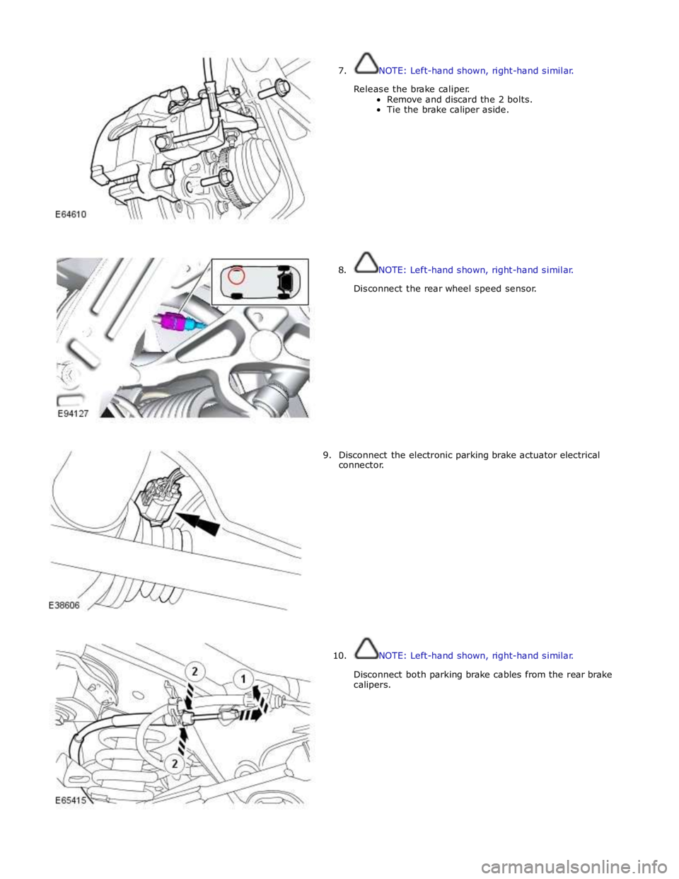
7. NOTE: Left-hand shown, right-hand similar.
Release the brake caliper.
Remove and discard the 2 bolts.
Tie the brake caliper aside.
8. NOTE: Left-hand shown, right-hand similar.
Disconnect the rear wheel speed sensor.
9. Disconnect the electronic parking brake actuator electrical
connector.
10. NOTE: Left-hand shown, right-hand similar.
Disconnect both parking brake cables from the rear brake
calipers.
Page 534 of 3039

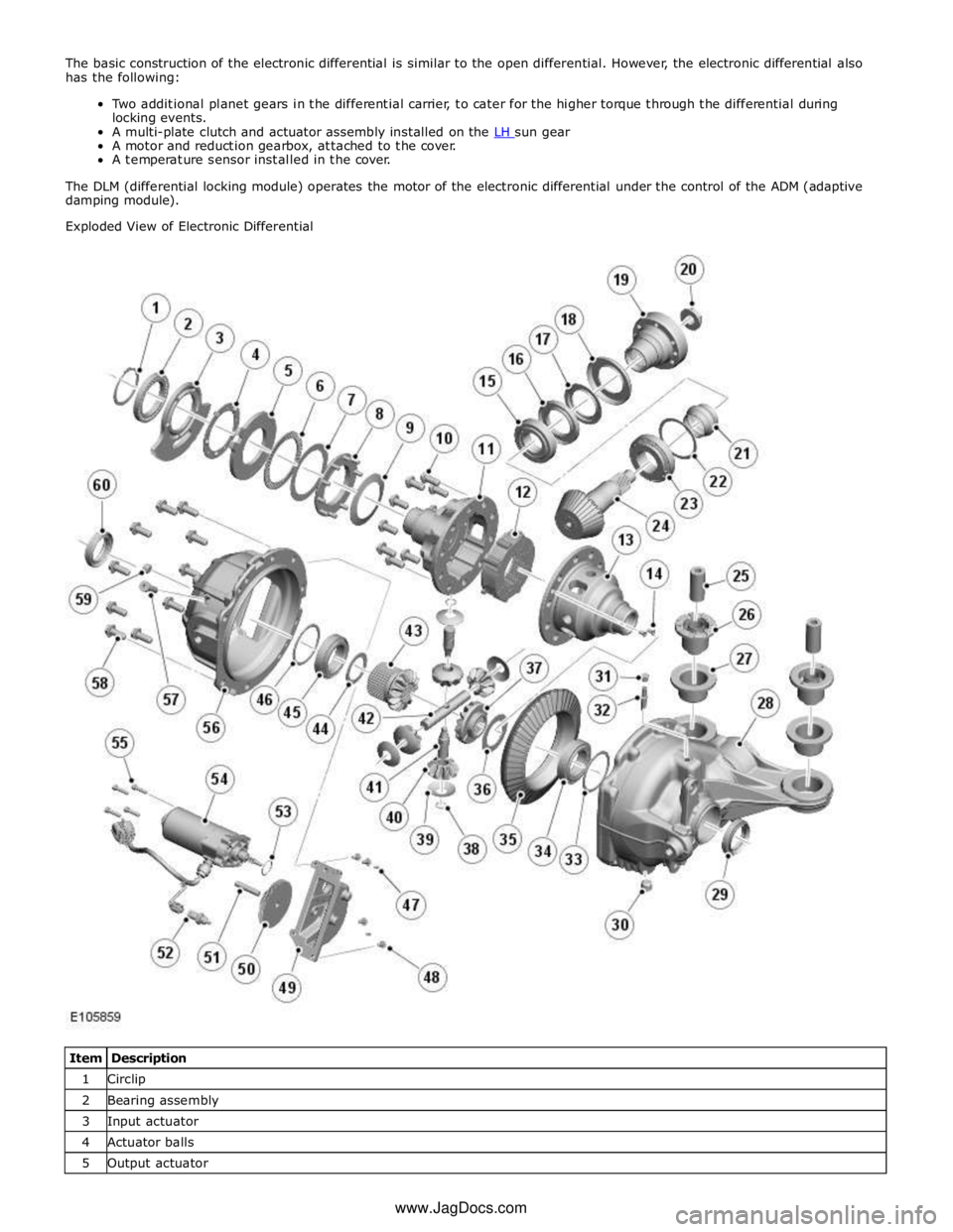
A motor and reduction gearbox, attached to the cover.
A temperature sensor installed in the cover.
The DLM (differential locking module) operates the motor of the electronic differential under the control of the ADM (adaptive
damping module).
Exploded View of Electronic Differential
Item Description 1 Circlip 2 Bearing assembly 3 Input actuator 4 Actuator balls 5 Output actuator www.JagDocs.com
Page 535 of 3039

Thrust race 7 Shim 8 Thrust plate 9 Dished washer 10 Bolt (10 off) 11 Clutch basket 12 Multi-plate clutch and pressure disc 13 Differential case 14 Screw (2 off) 15 Bearing assembly 16 Oil seal 17 Oil slinger inner 18 Oil slinger outer 19 Input flange 20 Pinion nut 21 Collapsible spacer 22 Shim 23 Bearing assembly 24 Pinion shaft 25 Mounting insulator inner (2 off) 26 Mounting insulator rubber (2 off) 27 Mounting insulator outer (2 off) 28 Carrier 29 Oil seal 30 Drain plug 31 Vent 32 Breather cap 33 Shim 34 Bearing assembly 35 Drive gear 36 Shim 37 RH sun gear 38 Circlip 39 Thrust washer (4 off) 40 Planet gear (4 off) 41 Pin (2 off) 42 Shaft 43 LH sun gear 44 Shim 45 Bearing assembly 46 Shim 47 Dowel (2 off) 48 Bolt (4 off) 49 Reduction gear casing 50 Reduction gear 51 Shaft 52 Temperature sensor 53 O-ring seal 54 Motor 55 Screw (4 off) 56 Cover 57 Output actuator locking pin 58 Bolt (9 off)
Page 536 of 3039

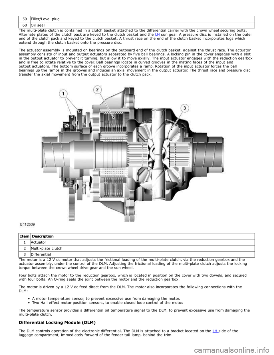
60 Oil seal The multi-plate clutch is contained in a clutch basket attached to the differential carrier with the crown wheel securing bolts.
Alternate plates of the clutch pack are keyed to the clutch basket and the LH sun gear. A pressure disc is installed on the outer end of the clutch pack and keyed to the clutch basket. A thrust race on the end of the clutch basket incorporates lugs which
extend through the clutch basket onto the pressure disc.
The actuator assembly is mounted on bearings on the outboard end of the clutch basket, against the thrust race. The actuator
assembly consists of input and output actuators separated by five ball bearings. A locking pin in the cover engages with a slot
in the output actuator to prevent it turning, but allow it to move axially. The input actuator engages with the reduction gearbox
and is free to rotate relative to the cover. Ball bearings locate in curved grooves in the mating faces of the input and
output actuators. The bottom surface of each groove incorporates a ramp. Rotation of the input actuator forces the ball
bearings up the ramps in the grooves and induces an axial movement in the output actuator. The thrust race and pressure disc
transfer the axial movement from the output actuator to the clutch pack.
Item Description 1 Actuator 2 Multi-plate clutch 3 Differential The motor is a 12 V dc motor that adjusts the frictional loading of the multi-plate clutch, via the reduction gearbox and the
actuator assembly, under the control of the DLM. Adjusting the frictional loading of the multi-plate clutch adjusts the locking
torque between the crown wheel drive gear and the sun wheel.
Four bolts attach the motor to the reduction gearbox, which is located in position on the cover with two dowels, and secured
with four bolts. An O-ring seals the joint between the motor and the reduction gearbox.
The motor is driven by a 12 V dc feed direct from the DLM. The motor also incorporates the following connections with the
DLM:
A motor temperature sensor, to prevent excessive use from damaging the motor.
Two Hall effect motor position sensors, to enable closed loop control of the motor.
The temperature sensor provides a differential oil temperature signal to the DLM, to prevent excessive use from damaging the
multi-plate clutch.
Differential Locking Module (DLM)
The DLM controls operation of the electronic differential. The DLM is attached to a bracket located on the LH side of the luggage compartment, immediately forward of the fender tail lamp, behind the trim.
Page 582 of 3039

Brake System - General Information - Brake System
Diagnosis and Testing
Principle of Operation Published: 11-May-2011
For a detailed description of the brake system, refer to the relevant Description and Operation sections in the workshop
manual. REFER to:
Front Disc Brake (206-03, Description and Operation),
Front Disc Brake (206-03, Description and Operation),
Front Disc Brake (206-03, Description and Operation),
Rear Disc Brake (206-04, Description and Operation),
Rear Disc Brake (206-04, Description and Operation),
Rear Disc Brake (206-04, Description and Operation),
Parking Brake (206-05 Parking Brake and Actuation, Description and Operation), Parking Brake (206-05 Parking Brake and Actuation, Description and Operation), Parking Brake (206-05 Parking Brake and Actuation, Description and Operation), Hydraulic Brake Actuation (206-06 Hydraulic Brake Actuation, Description and Operation), Hydraulic Brake Actuation (206-06 Hydraulic Brake Actuation, Description and Operation), Hydraulic Brake Actuation (206-06 Hydraulic Brake Actuation, Description and Operation), Brake Booster (206-07 Power Brake Actuation, Description and Operation), Brake Booster (206-07 Power Brake Actuation, Description and Operation), Brake Booster (206-07, Description and Operation).
Inspection and Verification
Visually examine the front and rear wheel and tire assemblies for damage such as uneven wear patterns, tread worn out or
sidewall damage. Verify the tires are the same size, type and, where possible, same manufacturer. Replace the damaged
wheel or excessively worn tire.
Wheels and tires must be cleared of any foreign matter and tire pressures adjusted to the correct specification.
If the tires exhibit uneven wear or feathering, the cause must be corrected. Check the steering and suspension components for
damage or wear and, if necessary, check and adjust front wheel alignment. REFER to: (204-00 Suspension System - General
Information)
Specifications (Specifications), Front Toe Adjustment (General Procedures).
Visual Inspection
Mechanical Electrical
Brake master cylinder
Brake caliper piston(s)
Brake discs
Wheel bearings
Brake pads
Power brake booster
Brake pedal linkage
Brake booster vacuum hose
Tires
Debris
Parking brake actuator
Parking brake module
Parking brake switch
Damaged or corroded wiring harness
Brake master cylinder fluid level switch Road Test
Carry out a road test to compare actual vehicle braking performance with the performance standards expected by the driver.
The ability of the test driver to make valid comparisons and detect performance deficiencies will depend on experience.
The driver should have a thorough knowledge of brake system operation and accepted general performance guidelines to make
good comparisons and detect performance concerns.
An experienced brake technician will always establish a route that will be used for all brake diagnosis road tests. The roads
selected will be reasonably smooth and level. Gravel or bumpy roads are not suitable because the surface does not allow the
tires to grip the road equally. Crowned roads should be avoided because of the large amount of weight shifted to the low set
of wheels on this type of road. Once the route is established and consistently used, the road surface variable can be
eliminated from the test results.
Before a road test, obtain a complete description of the customer concerns or suspected condition. From the description, the
technician's experience will allow the technician to match possible causes with symptoms. Certain components will be tagged
as possible suspects while others will be eliminated by the evidence. More importantly, the customer description can reveal
unsafe conditions which should be checked or corrected before the road test. The description will also help form the basic
approach to the road test by narrowing the concern to specific components, vehicle speed or conditions.
Begin the road test with a general brake performance check. Keeping the description of the concern in mind, test the brakes at
different vehicle speeds using both light and heavy pedal pressure. To determine if the concern is in the front or rear braking
system, use the brake pedal and then use the parking brake control. If the condition (pull, vibration, pulsation) occurs only
with the parking brake, the concern is in the rear brake system.
Page 644 of 3039

Parking brake module retaining bolts 4 - 35 Parking brake release actuator retaining bolts 20 15 -