Module control functions JAGUAR XFR 2010 1.G Owner's Manual
[x] Cancel search | Manufacturer: JAGUAR, Model Year: 2010, Model line: XFR, Model: JAGUAR XFR 2010 1.GPages: 3039, PDF Size: 58.49 MB
Page 2146 of 3039
Check the Starter Relay circuit.
NOTE: On petrol engine variants, due to Smart Start, both sides of Relay Coil are switched directly from ECM (If
conditions correct). On diesel engine variants the low side only is switched directly from the ECM.
Check that the Steering Column Lock correctly operates and the steering wheel can turn freely.
Check that the High Speed CAN network is not malfunctioning, i.e. the CAN circuit is open or short circuit. This would mean
that the instrument cluster and ECM would be unable to communicate resulting in no Challenge being performed to enable the
ECM. This would be supported by LED Flash Code 24, see PATS Fault Code Table.
Also check the CAN network between the ABS module and the CJB. The CJB uses the CAN_BrakePressureTMC signal to
determine if the brake pedal has been pressed in order to allow an engine crank. The CJB uses a value of 0x05, if the CJB sees
a value less than this, it will not enable the Crank Request Output.
Engine cranks but will not start
If the Engine is cranking it means that the ECM has passed the authorisation required with the Instrument Cluster. If this
authorisation failed, the ECM would not engage the starter relay. This could be confirmed by verifying the PATS LED prove out
(illuminated solid for 3 seconds) or by reading DTCs from the instrument cluster and ECM.
In this case, the fuel pump circuit should be verified. The Fuel Pump Delivery Module (FPDM), which is supplied via the RJB
(authentication required with the instrument cluster) and controlled by the ECM, supplies the fuel pump.
In all cases of suspected non-start issues, the most logical failure modes should be eliminated first. i.e.
1. Check all relevant supplies and grounds to the relevant modules listed herein.
2. Note any unusual behaviour from other systems/functionality.
3. Note any functions that are not operating as expected.
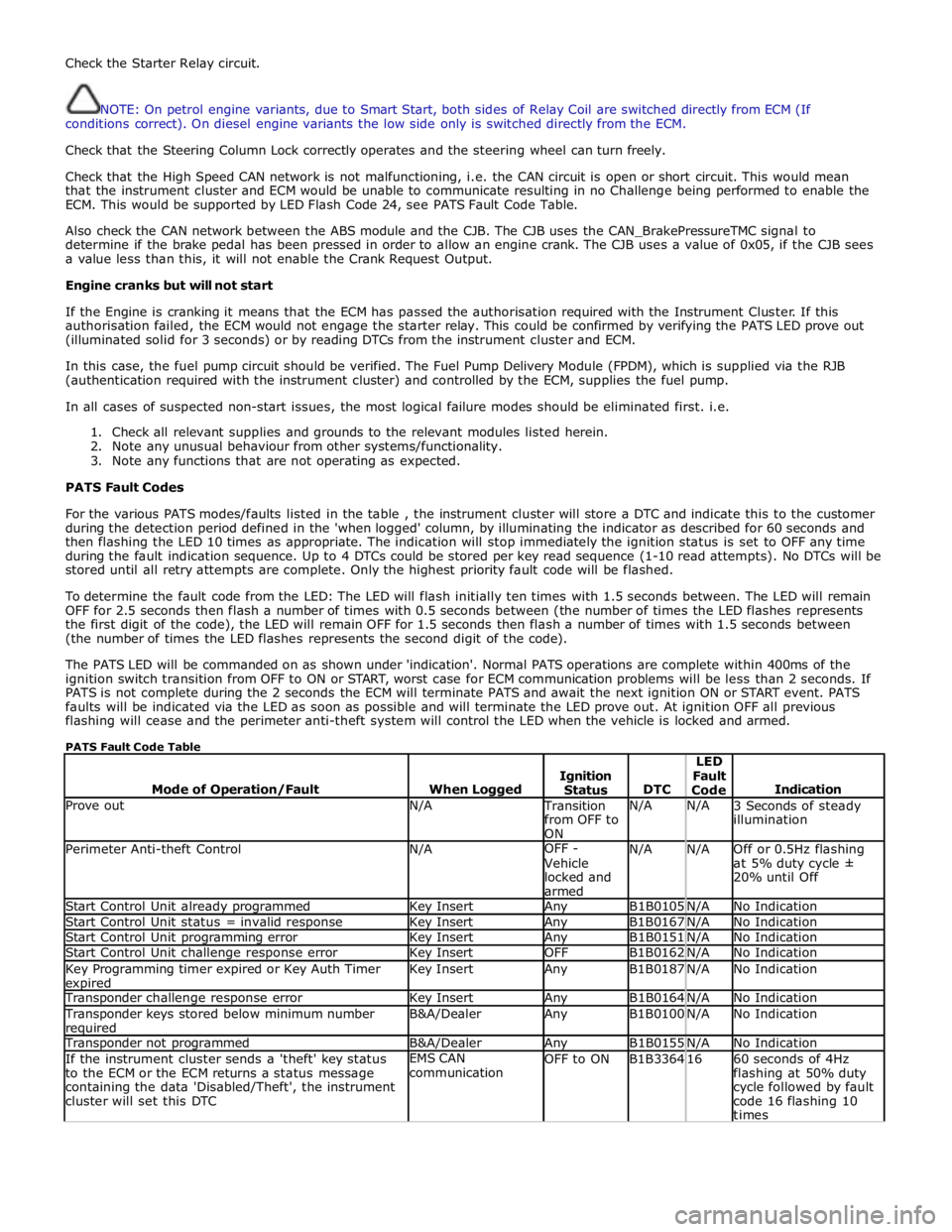
PATS Fault Codes
For the various PATS modes/faults listed in the table , the instrument cluster will store a DTC and indicate this to the customer
during the detection period defined in the 'when logged' column, by illuminating the indicator as described for 60 seconds and
then flashing the LED 10 times as appropriate. The indication will stop immediately the ignition status is set to OFF any time
during the fault indication sequence. Up to 4 DTCs could be stored per key read sequence (1-10 read attempts). No DTCs will be
stored until all retry attempts are complete. Only the highest priority fault code will be flashed.
To determine the fault code from the LED: The LED will flash initially ten times with 1.5 seconds between. The LED will remain
OFF for 2.5 seconds then flash a number of times with 0.5 seconds between (the number of times the LED flashes represents
the first digit of the code), the LED will remain OFF for 1.5 seconds then flash a number of times with 1.5 seconds between
(the number of times the LED flashes represents the second digit of the code).
The PATS LED will be commanded on as shown under 'indication'. Normal PATS operations are complete within 400ms of the
ignition switch transition from OFF to ON or START, worst case for ECM communication problems will be less than 2 seconds. If
PATS is not complete during the 2 seconds the ECM will terminate PATS and await the next ignition ON or START event. PATS
faults will be indicated via the LED as soon as possible and will terminate the LED prove out. At ignition OFF all previous
flashing will cease and the perimeter anti-theft system will control the LED when the vehicle is locked and armed.
PATS Fault Code Table
Mode of Operation/Fault
When Logged
Ignition
Status
DTC LED
Fault
Code
Indication Prove out N/A Transition
from OFF to
ON N/A N/A
3 Seconds of steady
illumination Perimeter Anti-theft Control N/A OFF -
Vehicle
locked and
armed N/A N/A
Off or 0.5Hz flashing
at 5% duty cycle ±
20% until Off Start Control Unit already programmed Key Insert Any B1B0105 N/A No Indication Start Control Unit status = invalid response Key Insert Any B1B0167 N/A No Indication Start Control Unit programming error Key Insert Any B1B0151 N/A No Indication Start Control Unit challenge response error Key Insert OFF B1B0162 N/A No Indication Key Programming timer expired or Key Auth Timer expired Key Insert Any B1B0187 N/A No Indication Transponder challenge response error Key Insert Any B1B0164 N/A No Indication Transponder keys stored below minimum number required B&A/Dealer Any B1B0100 N/A No Indication Transponder not programmed B&A/Dealer Any B1B0155 N/A No Indication If the instrument cluster sends a 'theft' key status
to the ECM or the ECM returns a status message
containing the data 'Disabled/Theft', the instrument
cluster will set this DTC EMS CAN
communication OFF to ON B1B3364 16
60 seconds of 4Hz
flashing at 50% duty
cycle followed by fault
code 16 flashing 10
times
Page 2170 of 3039
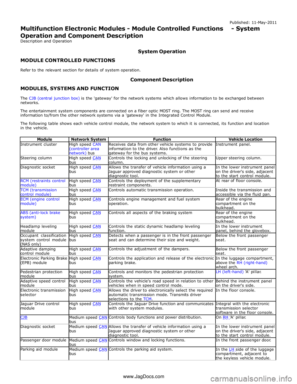
Instrument cluster
High speed CAN
(controller area network) bus Receives data from other vehicle systems to provide
information to the driver. Also functions as the gateway for the bus systems. Instrument panel. Steering column
High speed CAN bus Controls the locking and unlocking of the steering
column. Upper steering column. Diagnostic socket
High speed CAN bus Allows the transfer of vehicle information using a
Jaguar approved diagnostic system or other diagnostic tool. In the lower instrument panel
on the driver's side, adjacent
to the start control module. RCM (restraints control module) High speed CAN bus Controls the deployment of the supplementary
restraint components. At rear of floor console. TCM (transmission
control module) High speed CAN bus Controls automatic transmission operation.
Inside the transmission and
accessible via the fluid pan. ECM (engine control
module) High speed CAN bus Controls engine management and fuel system
operation. Rear of the engine
compartment on the
bulkhead. ABS (anti-lock brake
system) High speed CAN bus Controls all aspects of the braking system
Rear of the engine
compartment on the
bulkhead. Headlamp leveling
module High speed CAN bus Controls the static dynamic headlamp leveling
function. In the lower instrument panel, behind the glovebox. Occupant classification
system control module (NAS only) High speed CAN bus Detects when a passenger is in the front passenger
seat and can determine their size and weight. Below the front passenger
seat. Adaptive damping
control module High speed CAN bus Controls the adjustment of the dampers.
Below the front passenger
seat. Electronic Parking Brake
(EPB) module High speed CAN bus Controls the application and release of the electronic
parking brake. In the luggage compartment,
above the RH (right-hand)
wheel arch. Pedestrian protection
module High speed CAN bus Controls and monitors the pedestrian protection system. LH (left-hand) 'A' pillar. Adaptive speed control
module High speed CAN bus Controls the vehicle's road speed in relation to other
vehicles when in speed control mode. Behind the instrument panel
on the driver's side. Electronic transmission
selector High speed CAN bus Allows the driver to electronically select the required
automatic transmission mode. Transmits driver
selections to the TCM. In the floor console. Jaguar Drive control
module High speed CAN bus Controls the Jaguar Drive function and communicates
with other system modules. Integral with the electronic
transmission selector
software in the floor console. CJB
Medium speed CAN bus Controls body functions and power distribution. On RH 'A' pillar. Diagnostic socket
Medium speed CAN bus Allows the transfer of vehicle information using a
Jaguar approved diagnostic system or other diagnostic tool. In the lower instrument panel
on the driver's side, adjacent
to the start control module. Passenger door module
Medium speed CAN bus Controls window and locking functions. In the front passenger door. Parking aid module
Medium speed CAN bus Controls the parking aid system.
In the LH side of the luggage compartment, adjacent to
the keyless vehicle module. www.JagDocs.com
Page 2171 of 3039
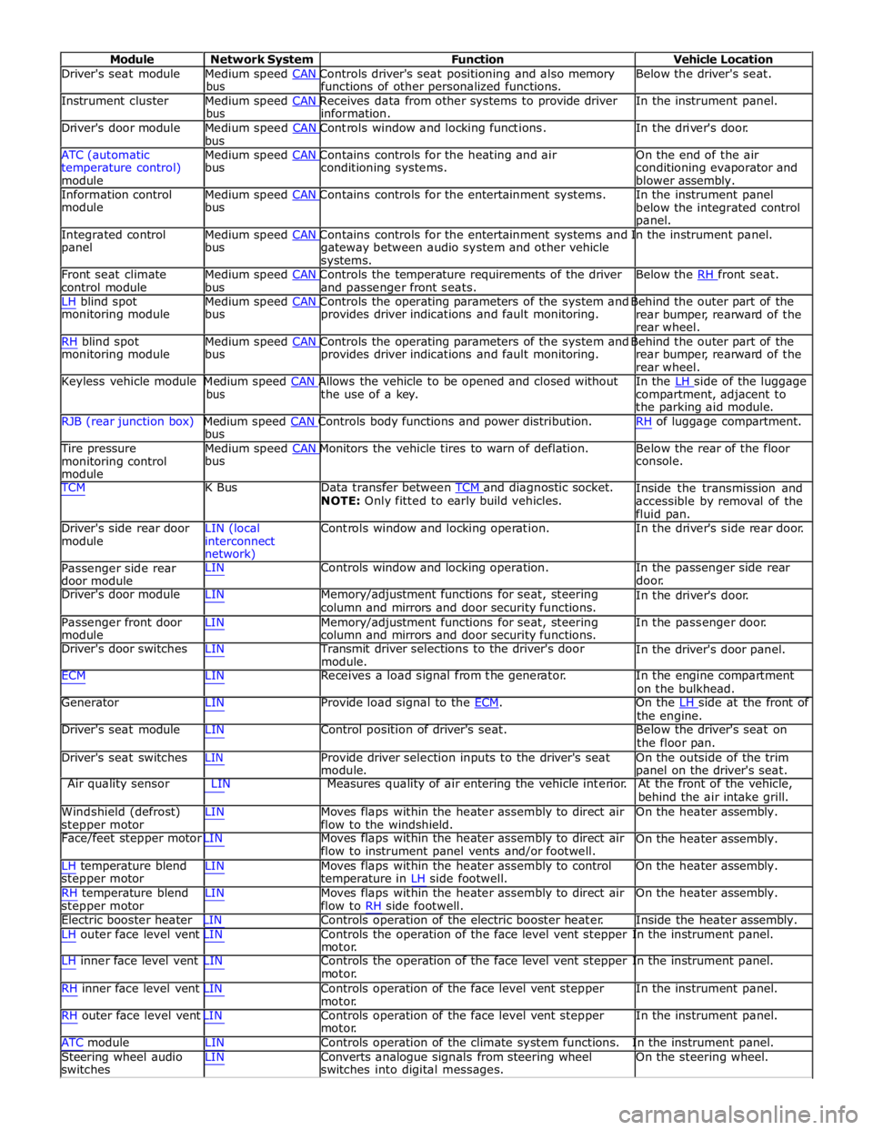
Module Network System Function Vehicle Location
Driver's seat module Medium speed CAN Controls driver's seat positioning and also memory Below the driver's seat. bus functions of other personalized functions.
Instrument cluster Medium speed CAN Receives data from other systems to provide driver In the instrument panel. bus information.
Driver's door module Medium speed CAN Controls window and locking functions. In the driver's door. bus
ATC (automatic Medium speed CAN Contains controls for the heating and air On the end of the air
temperature control)
module bus conditioning systems.
conditioning evaporator and
blower assembly.
Information control Medium speed CAN Contains controls for the entertainment systems. In the instrument panel module bus
below the integrated control
panel.
Integrated control Medium speed CAN Contains controls for the entertainment systems and In the instrument panel. panel bus
gateway between audio system and other vehicle
systems.
Front seat climate Medium speed CAN Controls the temperature requirements of the driver Below the RH front seat. control module bus and passenger front seats.
LH blind spot Medium speed CAN Controls the operating parameters of the system and Behind the outer part of the monitoring module bus provides driver indications and fault monitoring.
rear bumper, rearward of the
rear wheel.
RH blind spot Medium speed CAN Controls the operating parameters of the system and Behind the outer part of the monitoring module bus provides driver indications and fault monitoring.
rear bumper, rearward of the
rear wheel.
Keyless vehicle module Medium speed CAN Allows the vehicle to be opened and closed without In the LH side of the luggage bus the use of a key.
compartment, adjacent to
the parking aid module.
RJB (rear junction box) Medium speed CAN Controls body functions and power distribution. RH of luggage compartment. bus
Tire pressure Medium speed CAN Monitors the vehicle tires to warn of deflation. Below the rear of the floor monitoring control
module bus console.
TCM K Bus Data transfer between TCM and diagnostic socket. NOTE: Only fitted to early build vehicles. Inside the transmission and
accessible by removal of the
fluid pan.
Driver's side rear door
module LIN (local
interconnect
network) Controls window and locking operation. In the driver's side rear door.
Passenger side rear
door module LIN Controls window and locking operation. In the passenger side rear
door.
Driver's door module LIN Memory/adjustment functions for seat, steering
column and mirrors and door security functions. In the driver's door.
Passenger front door
module LIN Memory/adjustment functions for seat, steering
column and mirrors and door security functions. In the passenger door.
Driver's door switches LIN Transmit driver selections to the driver's door
module. In the driver's door panel.
ECM LIN Receives a load signal from the generator. In the engine compartment
on the bulkhead.
Generator LIN Provide load signal to the ECM. On the LH side at the front of the engine.
Driver's seat module LIN Control position of driver's seat. Below the driver's seat on
the floor pan.
Driver's seat switches LIN Provide driver selection inputs to the driver's seat
module. On the outside of the trim
panel on the driver's seat.
Air quality sensor LIN Measures quality of air entering the vehicle interior. At the front of the vehicle,
behind the air intake grill.
Windshield (defrost)
stepper motor LIN Moves flaps within the heater assembly to direct air
flow to the windshield. On the heater assembly.
Face/feet stepper motor LIN Moves flaps within the heater assembly to direct air
flow to instrument panel vents and/or footwell. On the heater assembly.
LH temperature blend
stepper motor
RH temperature blend
stepper motor LIN Moves flaps within the heater assembly to control
temperature in LH side footwell.
LIN Moves flaps within the heater assembly to direct air
flow to RH side footwell. On the heater assembly.
On the heater assembly.
Electric booster heater LIN Controls operation of the electric booster heater. Inside the heater assembly.
LH outer face level vent LIN Controls the operation of the face level vent stepper In the instrument panel.
motor.
LH inner face level vent LIN Controls the operation of the face level vent stepper In the instrument panel.
motor.
RH inner face level vent LIN Controls operation of the face level vent stepper
motor.
RH outer face level vent LIN Controls operation of the face level vent stepper
motor. In the instrument panel.
In the instrument panel.
ATC module LIN Controls operation of the climate system functions. In the instrument panel.
Steering wheel audio
switches LIN Converts analogue signals from steering wheel
switches into digital messages. On the steering wheel.
Page 2172 of 3039
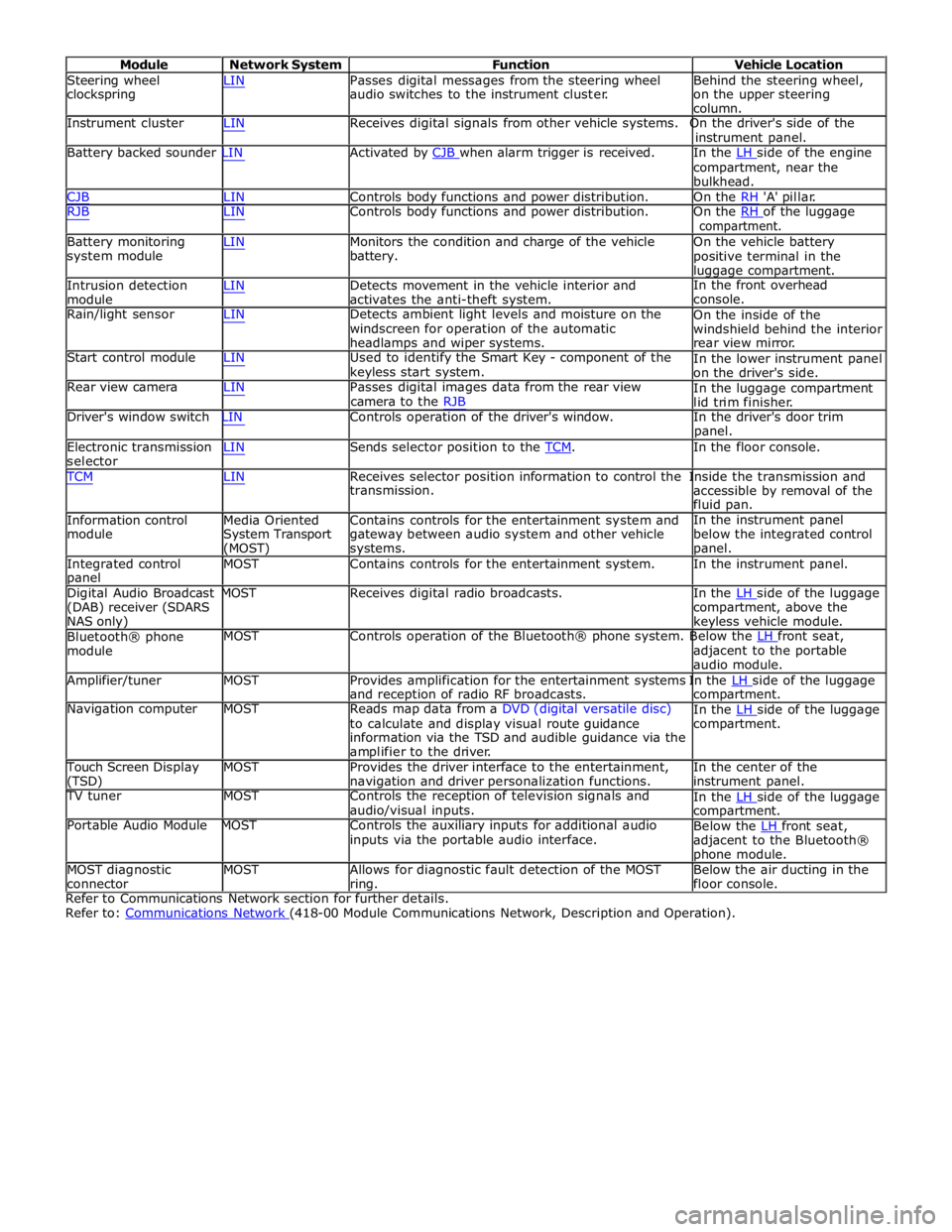
Module Network System Function Vehicle Location
Steering wheel
clockspring LIN Passes digital messages from the steering wheel
audio switches to the instrument cluster. Behind the steering wheel,
on the upper steering
column.
Instrument cluster LIN Receives digital signals from other vehicle systems. On the driver's side of the
instrument panel.
Battery backed sounder LIN Activated by CJB when alarm trigger is received. In the LH side of the engine compartment, near the
bulkhead.
CJB LIN Controls body functions and power distribution. On the RH 'A' pillar.
RJB LIN Controls body functions and power distribution. On the RH of the luggage compartment.
Battery monitoring
system module
Intrusion detection
module LIN Monitors the condition and charge of the vehicle
battery.
LIN Detects movement in the vehicle interior and
activates the anti-theft system. On the vehicle battery
positive terminal in the
luggage compartment.
In the front overhead
console.
Rain/light sensor LIN Detects ambient light levels and moisture on the
windscreen for operation of the automatic
headlamps and wiper systems.
Start control module LIN Used to identify the Smart Key - component of the
keyless start system.
Rear view camera LIN Passes digital images data from the rear view
camera to the RJB On the inside of the
windshield behind the interior
rear view mirror.
In the lower instrument panel
on the driver's side.
In the luggage compartment
lid trim finisher.
Driver's window switch LIN Controls operation of the driver's window. In the driver's door trim
panel.
Electronic transmission
selector LIN Sends selector position to the TCM. In the floor console. TCM LIN Receives selector position information to control the Inside the transmission and
Information control
module
Media Oriented
System Transport
(MOST) transmission.
Contains controls for the entertainment system and
gateway between audio system and other vehicle
systems. accessible by removal of the
fluid pan.
In the instrument panel
below the integrated control
panel.
Integrated control
panel MOST Contains controls for the entertainment system. In the instrument panel.
Digital Audio Broadcast MOST Receives digital radio broadcasts. In the LH side of the luggage (DAB) receiver (SDARS
NAS only)
Bluetooth® phone
module compartment, above the
keyless vehicle module.
MOST Controls operation of the Bluetooth® phone system. Below the LH front seat, adjacent to the portable
audio module.
Amplifier/tuner MOST Provides amplification for the entertainment systems In the LH side of the luggage and reception of radio RF broadcasts.
Navigation computer MOST Reads map data from a DVD (digital versatile disc)
to calculate and display visual route guidance
information via the TSD and audible guidance via the
amplifier to the driver. compartment.
In the LH side of the luggage compartment.
Touch Screen Display
(TSD) MOST Provides the driver interface to the entertainment,
navigation and driver personalization functions. In the center of the
instrument panel.
TV tuner MOST Controls the reception of television signals and
audio/visual inputs.
Portable Audio Module MOST Controls the auxiliary inputs for additional audio
inputs via the portable audio interface. In the LH side of the luggage compartment.
Below the LH front seat, adjacent to the Bluetooth®
phone module.
MOST diagnostic
connector MOST Allows for diagnostic fault detection of the MOST
ring. Below the air ducting in the
floor console.
Refer to Communications Network section for further details.
Refer to: Communications Network (418-00 Module Communications Network, Description and Operation).
Page 2173 of 3039
Multifunction Electronic Modules - Driver Door Module (DDM)
Diagnosis and Testing
Description and Operation Published: 11-May-2011
For a detailed description of the multifunction electronic control modules, refer to the relevant Description and Operation
sections in the workshop manual. REFER to: (419-10 Multifunction Electronic Modules)
Module Controlled Functions (Description and Operation), Module Controlled Functions (Description and Operation), Module Controlled Functions (Description and Operation).
Inspection and Verification
CAUTION: Diagnosis by substitution from a donor vehicle is NOT acceptable. Substitution of control modules does not
guarantee confirmation of a fault, and may also cause additional faults in the vehicle being tested and/or the donor vehicle.
1. Verify the customer concern.
2. Visually inspect for obvious signs of damage and system integrity.
3. If an obvious cause for an observed or reported concern is found, correct the cause (if possible) before proceeding to
the next step.
4. If the cause is not visually evident, check for Diagnostic Trouble Codes (DTCs) and refer to the DTC Index.
DTC Index
CAUTION: When probing connectors to take measurements in the course of the pinpoint tests, use the adaptor kit, part
number 3548-1358-00.
NOTES:
If the control module or a component is suspect and the vehicle remains under manufacturer warranty, refer to the
Warranty Policy and Procedures manual (section B1.2), or determine if any prior approval programme is in operation, prior to
the installation of a new module/component.
Generic scan tools may not read the codes listed, or may read only five digit codes. Match the five digits from the scan
tool to the first five digits of the seven digit code listed to identify the fault (the last two digits give additional information
read by the manufacturer approved diagnostic system).
When performing electrical voltage or resistance tests, always use a digital multimeter (DMM) accurate to three decimal
places, and with an up-to-date calibration certificate. When testing resistance, always take the resistance of the DMM leads
into account.
Check and rectify basic faults before beginning diagnostic routines involving pinpoint tests.
Inspect connectors for signs of water ingress, and pins for damage and/or corrosion.
If DTCs are recorded and, after performing the pinpoint tests, a fault is not present, an intermittent concern may be the
cause. Always check for loose connections and corroded terminals.
DTC Description Possible Cause Action B10EB11
Driver door double
locking motor
Driver door double locking motor
control circuit - short to ground Refer to the electrical circuit diagrams and test driver
door double locking motor control circuit for short ground Electrical
Fuse(s)
Electrical connector(s)
Wiring Harness Visual Inspection
Page 2178 of 3039

Published: 11-May-2011
Multifunction Electronic Modules - Remote Keyless Entry (RKE) Module
Diagnosis and Testing
Principles of Operation
For a detailed description of the Remote Keyless Entry system, refer to the relevant Description and Operation sections in the
workshop manual. REFER to: (419-10 Multifunction Electronic Modules)
Module Controlled Functions (Description and Operation), Module Controlled Functions (Description and Operation), Module Controlled Functions (Description and Operation).
Inspection and Verification
CAUTION: Diagnosis by substitution from a donor vehicle is NOT acceptable. Substitution of control modules does not
guarantee confirmation of a fault, and may also cause additional faults in the vehicle being tested and/or the donor vehicle.
1. Verify the customer concern.
2. Visually inspect for obvious signs of damage and system integrity.
Visual Inspection
Mechanical Electrical
Misaligned door(s), hood or luggage compartment lid
Door latch(s)
Actuating rod(s)
Exterior door handle(s)
Interior door handle(s)
Door lock cylinder
Cable(s)
Luggage compartment lid exterior release switch
Fuse(s)
Wiring harness
Electrical connector(s)
Door lock actuator(s)
Remote transmitter batteries
Vehicle battery
Remote transmitter
Door lock switch(s)
3. If an obvious cause for an observed or reported concern is found, correct the cause (if possible) before proceeding to
the next step.
4. If the cause is not visually evident, check for Diagnostic Trouble Codes (DTCs) and refer to the DTC Index.
DTC Index
CAUTION: When probing connectors to take measurements in the course of the pinpoint tests, use the adaptor kit, part
number 3548-1358-00.
NOTES:
If the control module or a component is suspect and the vehicle remains under manufacturer warranty, refer to the
Warranty Policy and Procedures manual (section B1.2), or determine if any prior approval programme is in operation, prior to
the installation of a new module/component.
Generic scan tools may not read the codes listed, or may read only five digit codes. Match the five digits from the scan
tool to the first five digits of the seven digit code listed to identify the fault (the last two digits give additional information
read by the manufacturer approved diagnostic system).
When performing electrical voltage or resistance tests, always use a digital multimeter (DMM) accurate to three decimal
places, and with an up-to-date calibration certificate. When testing resistance, always take the resistance of the DMM leads
into account.
Check and rectify basic faults before beginning diagnostic routines involving pinpoint tests.
Inspect connectors for signs of water ingress, and pins for damage and/or corrosion.
If DTCs are recorded and, after performing the pinpoint tests, a fault is not present, an intermittent concern may be the
cause. Always check for loose connections and corroded terminals.
Page 2182 of 3039
Published: 11-May-2011
Multifunction Electronic Modules - Passenger Door Module (PDM)
Diagnosis and Testing
Description and Operation
For a detailed description of the multifunction electronic control modules, refer to the relevant Description and Operation
sections in the workshop manual. REFER to: (419-10 Multifunction Electronic Modules)
Module Controlled Functions (Description and Operation), Module Controlled Functions (Description and Operation), Module Controlled Functions (Description and Operation).
Inspection and Verification
CAUTION: Diagnosis by substitution from a donor vehicle is NOT acceptable. Substitution of control modules does not
guarantee confirmation of a fault, and may also cause additional faults in the vehicle being tested and/or the donor vehicle.
1. Verify the customer concern.
2. Visually inspect for obvious signs of damage and system integrity.
3. If an obvious cause for an observed or reported concern is found, correct the cause (if possible) before proceeding to
the next step.
4. If the cause is not visually evident, check for Diagnostic Trouble Codes (DTCs) and refer to the DTC Index.
DTC Index
CAUTION: When probing connectors to take measurements in the course of the pinpoint tests, use the adaptor kit, part
number 3548-1358-00.
NOTES:
If the control module or a component is suspect and the vehicle remains under manufacturer warranty, refer to the
Warranty Policy and Procedures manual (section B1.2), or determine if any prior approval programme is in operation, prior to
the installation of a new module/component.
Generic scan tools may not read the codes listed, or may read only five digit codes. Match the five digits from the scan
tool to the first five digits of the seven digit code listed to identify the fault (the last two digits give additional information
read by the manufacturer approved diagnostic system).
When performing electrical voltage or resistance tests, always use a digital multimeter (DMM) accurate to three decimal
places, and with an up-to-date calibration certificate. When testing resistance, always take the resistance of the DMM leads
into account.
Check and rectify basic faults before beginning diagnostic routines involving pinpoint tests.
Inspect connectors for signs of water ingress, and pins for damage and/or corrosion.
If DTCs are recorded and, after performing the pinpoint tests, a fault is not present, an intermittent concern may be the
cause. Always check for loose connections and corroded terminals.
DTC Description Possible Cause Action B10EB11
Driver door double
locking motor
Driver door double locking motor
control circuit - short to ground Refer to the electrical circuit diagrams and test driver
door double locking motor control circuit for short ground Electrical
Fuse(s)
Electrical connector(s)
Wiring Harness Visual Inspection
Page 2294 of 3039
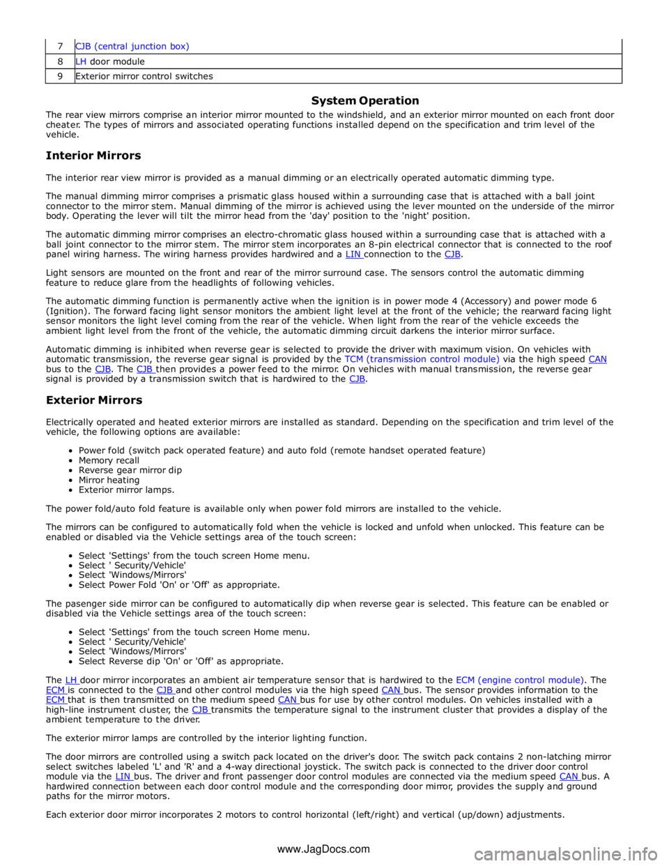
8 LH door module 9 Exterior mirror control switches
System Operation
The rear view mirrors comprise an interior mirror mounted to the windshield, and an exterior mirror mounted on each front door
cheater. The types of mirrors and associated operating functions installed depend on the specification and trim level of the
vehicle.
Interior Mirrors
The interior rear view mirror is provided as a manual dimming or an electrically operated automatic dimming type.
The manual dimming mirror comprises a prismatic glass housed within a surrounding case that is attached with a ball joint
connector to the mirror stem. Manual dimming of the mirror is achieved using the lever mounted on the underside of the mirror
body. Operating the lever will tilt the mirror head from the 'day' position to the 'night' position.
The automatic dimming mirror comprises an electro-chromatic glass housed within a surrounding case that is attached with a
ball joint connector to the mirror stem. The mirror stem incorporates an 8-pin electrical connector that is connected to the roof
panel wiring harness. The wiring harness provides hardwired and a LIN connection to the CJB.
Light sensors are mounted on the front and rear of the mirror surround case. The sensors control the automatic dimming
feature to reduce glare from the headlights of following vehicles.
The automatic dimming function is permanently active when the ignition is in power mode 4 (Accessory) and power mode 6
(Ignition). The forward facing light sensor monitors the ambient light level at the front of the vehicle; the rearward facing light
sensor monitors the light level coming from the rear of the vehicle. When light from the rear of the vehicle exceeds the
ambient light level from the front of the vehicle, the automatic dimming circuit darkens the interior mirror surface.
Automatic dimming is inhibited when reverse gear is selected to provide the driver with maximum vision. On vehicles with
automatic transmission, the reverse gear signal is provided by the TCM (transmission control module) via the high speed CAN bus to the CJB. The CJB then provides a power feed to the mirror. On vehicles with manual transmission, the reverse gear signal is provided by a transmission switch that is hardwired to the CJB.
Exterior Mirrors
Electrically operated and heated exterior mirrors are installed as standard. Depending on the specification and trim level of the
vehicle, the following options are available:
Power fold (switch pack operated feature) and auto fold (remote handset operated feature)
Memory recall
Reverse gear mirror dip
Mirror heating
Exterior mirror lamps.
The power fold/auto fold feature is available only when power fold mirrors are installed to the vehicle.
The mirrors can be configured to automatically fold when the vehicle is locked and unfold when unlocked. This feature can be
enabled or disabled via the Vehicle settings area of the touch screen:
Select 'Settings' from the touch screen Home menu.
Select ' Security/Vehicle'
Select 'Windows/Mirrors'
Select Power Fold 'On' or 'Off' as appropriate.
The pasenger side mirror can be configured to automatically dip when reverse gear is selected. This feature can be enabled or
disabled via the Vehicle settings area of the touch screen:
Select 'Settings' from the touch screen Home menu.
Select ' Security/Vehicle'
Select 'Windows/Mirrors'
Select Reverse dip 'On' or 'Off' as appropriate.
The LH door mirror incorporates an ambient air temperature sensor that is hardwired to the ECM (engine control module). The ECM is connected to the CJB and other control modules via the high speed CAN bus. The sensor provides information to the ECM that is then transmitted on the medium speed CAN bus for use by other control modules. On vehicles installed with a high-line instrument cluster, the CJB transmits the temperature signal to the instrument cluster that provides a display of the ambient temperature to the driver.
The exterior mirror lamps are controlled by the interior lighting function.
The door mirrors are controlled using a switch pack located on the driver's door. The switch pack contains 2 non-latching mirror
select switches labeled 'L' and 'R' and a 4-way directional joystick. The switch pack is connected to the driver door control
module via the LIN bus. The driver and front passenger door control modules are connected via the medium speed CAN bus. A hardwired connection between each door control module and the corresponding door mirror, provides the supply and ground
paths for the mirror motors.
Each exterior door mirror incorporates 2 motors to control horizontal (left/right) and vertical (up/down) adjustments. www.JagDocs.com
Page 2316 of 3039
supplies provide power for the movement motors in addition to the driver's seat switch pack. Power is only supplied to the
driver's seat module and the driver's seat switch pack when the ignition is on (power mode 6).
The driver's seat switch pack is connected to the driver's seat module by a LIN bus for the seat movement switches. Any selection for seat movement generates a message which is passed via the LIN to the driver's seat module. The seat module processes the request and operates the applicable seat function as required using the power supplies from the CJB.
Each seat motor contains a Hall position sensor. The sensor sends a feedback signal to the driver's seat module. The signal is
used for memory store and memory recall functions.
The lumbar adjustment switch on the driver's seat switch pack is wired direct to the lumbar pump and solenoids. The switch,
when moved to the inflate position for either the upper or lower inflatable cushion cell, provides a power supply to the lumbar
pump and simultaneously activates the applicable inflate solenoid valve. When the switch is released the pump stops and the
solenoid valve closes trapping the air in the inflatable cushion. When the switch is moved to the deflate position for either the
upper or lower inflatable cushion cell, power is supplied to the applicable deflate solenoid valve which opens to allow the air in
the cushion to escape. When the switch is released, the valve is closed and the remaining air in the cushion is retained.
FRONT SEATS - DESCRIPTION Component Description
The table below highlights the features available for each seating option.
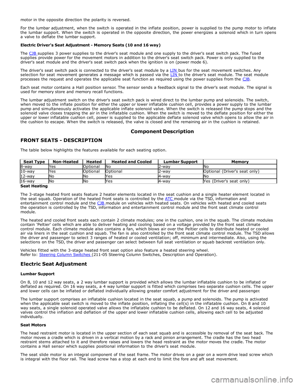
Seat Type Non-Heated Heated Heated and Cooled Lumbar Support Memory 8-way Yes Optional No 2-way No 10-way Yes Optional Optional 2-way Optional (Driver's seat only) 12-way No No Yes 4-way No 16-way No No Yes 4-way Yes (Driver's seat only) Seat Heating
The 3-stage heated front seats feature 2 heater elements located in the seat cushion and a single heater element located in
the seat squab. Operation of the heated front seats is controlled by the ATC module via the TSD, information and entertainment control module and the CJB module on vehicles with heated seats. On vehicles with heated and cooled seats the operation is controlled by the TSD, information and entertainment control module and the front seat climate control
module.
The heated and cooled front seats each contain 2 climate modules; one in the cushion, one in the squab. The climate modules
contain 'Peltier' cells which are able to deliver heating and cooling based on a voltage provided by the front seat climate
control module. Each climate module also contains a fan, which blows air over the Peltier cells to distribute heated or cooled
air via liners in the seat cushion and squab. The fan is also controlled by the front seat climate control module. The TSD allows
the driver and passenger to select 3 ranges of heated or cooled ventilation; off, minimum and intermediate. Also, using the
selections on the TSD, the driver and passenger can select between full seat ventilation or squab backrest ventilation only.
Vehicles fitted with the 3-stage heated front seat option also feature a heated steering wheel.
Refer to: Steering Column Switches (211-05 Steering Column Switches, Description and Operation).
Electric Seat Adjustment
Lumbar Support
On 8, 10 and 12 way seats, a 2 way lumbar support is provided which allows the lumbar inflatable cushion to be inflated or
deflated as required. On 16 way seats, a 4 way lumbar support is fitted which comprises two separate cushion cells. The upper
and lower cells can be inflated or deflated individually allowing greater comfort adjustment for the driver and passenger.
The lumbar support comprises an inflatable cushion located in the seat squab, a pump and solenoids. The pump is activated
when the applicable seat switch is moved to the inflate position, inflating the cell(s) in the inflatable cushion. On 8 and 10
way seats, a single solenoid operated valve allows the inflatable cushion to be deflated. On 12 and 16 way seats, 4 solenoid
valves control the inflation and deflation of the upper and lower inflatable cushion cells, allowing each cell to be adjusted
individually.
Seat Motors
The head restraint motor is located in the upper section of each seat squab and is accessible by removal of the seat back. The
motor moves a cradle which is driven in a vertical motion by a rack and pinion arrangement. The cradle has the two head
restraint stems attached to it and therefore raises and lowers the head restraint as the motor moves the cradle. The motor
contains a Hall sensor which supplies positional information to the driver's seat module.
The seat slide motor is an integral component of the seat frame. The motor drives on a gear on a worm drive lead screw which
is integral with the floor rail. The lead screw has a stop at each end to limit the fore and aft seat movement.
Page 2340 of 3039
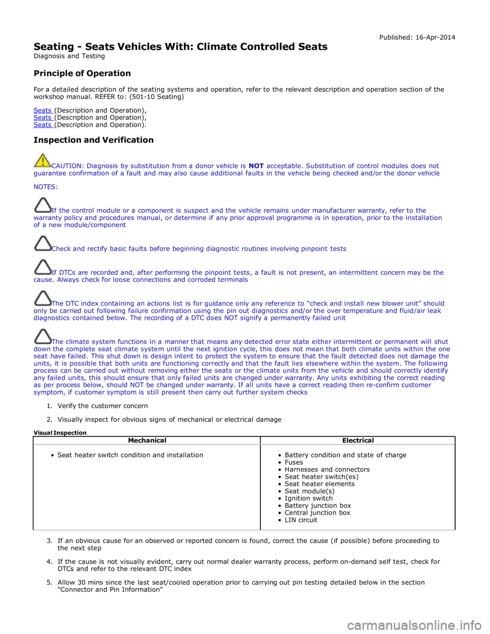
Seating - Seats Vehicles With: Climate Controlled Seats
Diagnosis and Testing
Principle of Operation Published: 16-Apr-2014
For a detailed description of the seating systems and operation, refer to the relevant description and operation section of the
workshop manual. REFER to: (501-10 Seating)
Seats (Description and Operation), Seats (Description and Operation), Seats (Description and Operation).
Inspection and Verification
CAUTION: Diagnosis by substitution from a donor vehicle is NOT acceptable. Substitution of control modules does not
guarantee confirmation of a fault and may also cause additional faults in the vehicle being checked and/or the donor vehicle
NOTES:
If the control module or a component is suspect and the vehicle remains under manufacturer warranty, refer to the
warranty policy and procedures manual, or determine if any prior approval programme is in operation, prior to the installation
of a new module/component
Check and rectify basic faults before beginning diagnostic routines involving pinpoint tests
If DTCs are recorded and, after performing the pinpoint tests, a fault is not present, an intermittent concern may be the
cause. Always check for loose connections and corroded terminals
The DTC index containing an actions list is for guidance only any reference to “check and install new blower unit” should
only be carried out following failure confirmation using the pin out diagnostics and/or the over temperature and fluid/air leak
diagnostics contained below. The recording of a DTC does NOT signify a permanently failed unit
The climate system functions in a manner that means any detected error state either intermittent or permanent will shut
down the complete seat climate system until the next ignition cycle, this does not mean that both climate units within the one
seat have failed. This shut down is design intent to protect the system to ensure that the fault detected does not damage the
units, it is possible that both units are functioning correctly and that the fault lies elsewhere within the system. The following
process can be carried out without removing either the seats or the climate units from the vehicle and should correctly identify
any failed units, this should ensure that only failed units are changed under warranty. Any units exhibiting the correct reading
as per process below, should NOT be changed under warranty. If all units have a correct reading then re-confirm customer
symptom, if customer symptom is still present then carry out further system checks
1. Verify the customer concern
2. Visually inspect for obvious signs of mechanical or electrical damage
Visual Inspection
Mechanical Electrical
Seat heater switch condition and installation
Battery condition and state of charge
Fuses
Harnesses and connectors
Seat heater switch(es)
Seat heater elements
Seat module(s)
Ignition switch
Battery junction box
Central junction box
LIN circuit
3. If an obvious cause for an observed or reported concern is found, correct the cause (if possible) before proceeding to
the next step
4. If the cause is not visually evident, carry out normal dealer warranty process, perform on-demand self test, check for
DTCs and refer to the relevant DTC index
5. Allow 30 mins since the last seat/cooled operation prior to carrying out pin testing detailed below in the section
"Connector and Pin Information"