Module control functions JAGUAR XFR 2010 1.G Owner's Guide
[x] Cancel search | Manufacturer: JAGUAR, Model Year: 2010, Model line: XFR, Model: JAGUAR XFR 2010 1.GPages: 3039, PDF Size: 58.49 MB
Page 2341 of 3039

6. Locate climate seat module, (refer to Electrical Information - Electrical Reference Library, contained in TOPIx) for
guidance on how to gain access to the connector(s)
7. Locate and disconnect relevant connector prior to pin test
8. Using ohm-meter to probe each heat/cooled unit pins (at rear of connector), reading should achieve no greater than 10
ohms after 1 minute (initial fluctuations in readings may occur using ohm-meter, post 1 minute readings will have
stabilized)
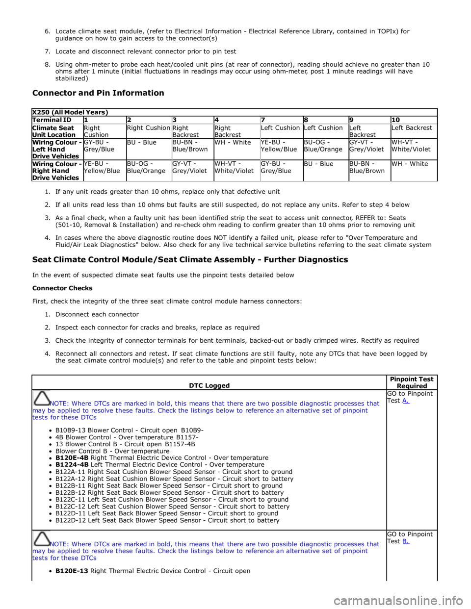
Connector and Pin Information
X250 (All Model Years) Terminal ID 1 2 3 4 7 8 9 10 Climate Seat
Unit Location Right
Cushion Right Cushion
Right
Backrest Right
Backrest Left Cushion Left Cushion
Left
Backrest Left Backrest Wiring Colour -
Left Hand
Drive Vehicles GY-BU -
Grey/Blue BU - Blue BU-BN -
Blue/Brown WH - White YE-BU - Yellow/Blue BU-OG -
Blue/Orange GY-VT -
Grey/Violet WH-VT -
White/Violet Wiring Colour -
Right Hand
Drive Vehicles YE-BU - Yellow/Blue BU-OG -
Blue/Orange GY-VT -
Grey/Violet WH-VT -
White/Violet GY-BU -
Grey/Blue BU - Blue BU-BN -
Blue/Brown WH - White
1. If any unit reads greater than 10 ohms, replace only that defective unit
2. If all units read less than 10 ohms but faults are still suspected, do not replace any units. Refer to step 4 below
3. As a final check, when a faulty unit has been identified strip the seat to access unit connector, REFER to: Seats
(501-10, Removal & Installation) and re-check ohm reading to confirm greater than 10 ohms prior to removing unit
4. In cases where the above diagnostic routine does NOT identify a failed unit, please refer to "Over Temperature and
Fluid/Air Leak Diagnostics" below. Also check for any live technical service bulletins referring to the seat climate system
Seat Climate Control Module/Seat Climate Assembly - Further Diagnostics
In the event of suspected climate seat faults use the pinpoint tests detailed below
Connector Checks
First, check the integrity of the three seat climate control module harness connectors:
1. Disconnect each connector
2. Inspect each connector for cracks and breaks, replace as required
3. Check the integrity of connector terminals for bent terminals, backed-out or badly crimped wires. Rectify as required
4. Reconnect all connectors and retest. If seat climate functions are still faulty, note any DTCs that have been logged by
the seat climate control module(s) and refer to the table and pinpoint tests below:
DTC Logged Pinpoint Test Required
NOTE: Where DTCs are marked in bold, this means that there are two possible diagnostic processes that
may be applied to resolve these faults. Check the listings below to reference an alternative set of pinpoint
tests for these DTCs
B10B9-13 Blower Control - Circuit open B10B9-
4B Blower Control - Over temperature B1157-
13 Blower Control B - Circuit open B1157-4B
Blower Control B - Over temperature
B120E-4B Right Thermal Electric Device Control - Over temperature
B1224-4B Left Thermal Electric Device Control - Over temperature
B122A-11 Right Seat Cushion Blower Speed Sensor - Circuit short to ground
B122A-12 Right Seat Cushion Blower Speed Sensor - Circuit short to battery
B122B-11 Right Seat Back Blower Speed Sensor - Circuit short to ground
B122B-12 Right Seat Back Blower Speed Sensor - Circuit short to battery
B122C-11 Left Seat Cushion Blower Speed Sensor - Circuit short to ground
B122C-12 Left Seat Cushion Blower Speed Sensor - Circuit short to battery
B122D-11 Left Seat Back Blower Speed Sensor - Circuit short to ground
B122D-12 Left Seat Back Blower Speed Sensor - Circuit short to battery GO to Pinpoint
Test A.
NOTE: Where DTCs are marked in bold, this means that there are two possible diagnostic processes that
may be applied to resolve these faults. Check the listings below to reference an alternative set of pinpoint
tests for these DTCs
B120E-13 Right Thermal Electric Device Control - Circuit open GO to Pinpoint
Test B.
Page 2493 of 3039

Item Description Note: A = Hardwired; N = Medium speed CAN 1 Battery 2 Megafuse (250 A) 3 CJB 4 Radio frequency receiver 5 Keylesss vehicle module 6 Door handle, lock/unlock switch and antenna - front passenger 7 Door latch, fast latch - front passenger 8 Door latch, fast latch - RH rear passenger 9 Door handle, lock/unlock switch and antenna - RH rear passenger 10 Door latch, fast latch - LH rear passenger 11 Door handle, lock/unlock switch and antenna - LH rear passenger 12 Door latch, fast latch - driver door 13 Door handle, lock/unlock switch and antenna - driver door
System Operation
The hinged panels are secured with latches and strikers. A remotely operated central locking system controls the locking and
unlocking of the door and luggage compartment latches. A radio frequency Smart Key allows the vehicle to be locked and
unlocked by pressing the appropriate handset buttons. Two levels of central locking system are available: remote central
locking and an optional passive entry system.
The passive entry and associated passive start system allows the driver to unlock and start the vehicle without using a vehicle
key in a door-lock or ignition switch. The passive entry system is an optional fitment while the passive start system is a
standard fitment on all vehicles. The passive start system is combined with the passive anti-theft immobilization system.
Refer to: Anti-Theft - Passive (419-01B Anti-Theft - Passive, Description and Operation).
Emergency access to the vehicle is provided by two concealed key barrels: one located in the front left-hand door handle and
one located on the underside of the luggage compartment lid finisher. An emergency, removable key blade is fitted into the
Smart Key.
Operation of either key barrel unlocks the vehicle but does not disarm the alarm system. The key barrels in the door and
luggage compartment lid are concealed by a plastic cover which can be removed by inserting the blade of the emergency key
into a slot in the cover.
Locking and unlocking conditions using the emergency key in the door key barrel:
If the alarm is not armed the vehicle can be centrally unlocked.
If the alarm is armed the door only can be opened and the alarm will be triggered.
The vehicle cannot be double locked or the alarm system armed using the emergency key.
The vehicle can be centrally locked and unlocked from inside using the interior handle release levers on the front doors only.
Central locking and unlocking can also be performed using lock and unlock buttons on the vehicle's fascia. The driver can select
locking options, single point entry or drive away locking for example, from a menu available on the touch screen.
Central Locking – Radio Frequency Remote System
The radio frequency central locking system, provides locking and unlocking of the vehicle from inside and outside of the
vehicle. The system is operated using buttons on the Smart Key, which transmits radio frequency signals to the central locking
radio frequency receiver.
The system provides additional security by double-locking the doors from outside the vehicle if the lock button, on the Smart
Key, is pressed twice within 3 seconds; this function is not applicable in North American Specification (NAS) and Japanese
markets.
Additional buttons on the Smart Key provide for the convenience operation of the luggage compartment lid release, headlamp
delay and panic alarm functions. A global open or close feature is also available in certain markets using the lock/unlock
buttons.
Passive Entry
On vehicles fitted with the optional passive entry system, the vehicle can be unlocked without the use of a key blade or
pressing buttons on the Smart Key. The Smart Key operates the passive entry system in addition to the passive start system.
Refer to: Anti-Theft - Passive (419-01B Anti-Theft - Passive, Description and Operation).
The passive entry system is controlled by the keyless vehicle module and five low frequency antennas. One antenna located in
each door handle and one antenna located behind the rear bumper cover.
When a vehicle door handle is pulled to the first five-percent of its travel and the Smart Key is within one meter of the handle;
the Smart Key receives the low-frequency signal transmitted from the keyless vehicle module. The Smart Key responds with a
radio frequency transmission of its authorization code. The radio frequency signal is received by the central locking radio-
frequency receiver and passed to the keyless vehicle module which checks and approves the code as valid. Once the handle is
Page 2615 of 3039

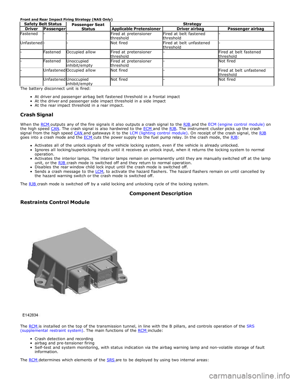
Driver Passenger Applicable Pretensioner Driver airbag Passenger airbag Fastened - -
Fired at pretensioner
threshold Fired at belt fastened
threshold - Unfastened - - Not fired
Fired at belt unfastened
threshold - - Fastened Occupied allow
Fired at pretensioner
threshold -
Fired at belt fastened
threshold - Fastened
Unoccupied inhibit/empty Fired at pretensioner
threshold - Not fired - Unfastened Occupied allow Not fired -
Fired at belt unfastened
threshold Unfastened
Unoccupied inhibit/empty Not fired - Not fired The battery disconnect unit is fired:
At driver and passenger airbag belt fastened threshold in a frontal impact
At the driver and passenger side impact threshold in a side impact
At the rear impact threshold in a rear impact.
Crash Signal
When the RCM outputs any of the fire signals it also outputs a crash signal to the RJB and the ECM (engine control module) on the high speed CAN. The crash signal is also hardwired to the ECM and the RJB. The instrument cluster picks up the crash signal from the high speed CAN and gateways it to the LCM (lighting control module). On receipt of the crash signal, the RJB goes into a crash mode and the ECM cuts the power supply to the fuel pump relay. In the crash mode, the RJB: Activates all of the unlock signals of the vehicle locking system, even if the vehicle is already unlocked.
Ignores all locking/superlocking inputs until it receives an unlock input, when it returns the locking system to normal
operation.
Activates the interior lamps. The interior lamps remain on permanently until they are manually switched off at the lamp
unit, or the RJB crash mode is switched off and they return to normal operation. Disables the rear window child lock input until the crash mode is switched off.
Sends a crash message to the LCM, to activate the hazard flashers. The hazard flashers remain on until cancelled by the hazard warning switch or the crash mode is switched off.
The RJB crash mode is switched off by a valid locking and unlocking cycle of the locking system.
Restraints Control Module Component Description
The RCM is installed on the top of the transmission tunnel, in line with the B pillars, and controls operation of the SRS (supplemental restraint system). The main functions of the RCM include:
Crash detection and recording
airbag and pre-tensioner firing
Self-test and system monitoring, with status indication via the airbag warning lamp and non-volatile storage of fault
information.
The RCM determines which elements of the SRS are to be deployed by using two internal areas: