Module control functions JAGUAR XFR 2010 1.G User Guide
[x] Cancel search | Manufacturer: JAGUAR, Model Year: 2010, Model line: XFR, Model: JAGUAR XFR 2010 1.GPages: 3039, PDF Size: 58.49 MB
Page 1886 of 3039
the secondary battery (if fitted) and passes through a grommet in the floorpan.
On new vehicles the primary battery positive terminal is fitted with a transit relay. The transit relay must removed using the
correct process detailed in the Pre Delivery Inspection (PDI) manual.
The battery negative terminal is fitted with a BMS control module. The control module is integral with the battery negative
cable and communicates with the GWM via a LIN bus connection. The battery condition information is passed to the GWM
which controls the generator output accordingly.
CAUTION: To avoid damage to the BMS control module, always use the body ground point in the engine compartment and
not the battery negative terminal when connecting a slave power supply.
Failure to use the recommended ground point will lead to the setting of a DTC. Incorrect information of battery condition will
be retained by the BMS control module due to the unmonitored current flow into the battery. The system will however,
recognize and compensate for the change in battery status after a period of time.
If a new battery is fitted, the BMS control module will require re-calibration using a Jaguar approved diagnostic system.
Replacement of the BMS control module requires no action as the control module will re-calibrate automatically.
SECONDARY BATTERY - DUAL BATTERY VEHICLES ONLY
The secondary battery is located in a tray on the next of the primary battery and is secured to the DBJB with a bracket. The
battery negative (-) terminal is connected via a cable to the vehicle body. The positive (+) terminal is connected by a cable to
the DBJB. The battery is vented via a tube which is connected with a T piece to the vent from the primary battery and passes
through a grommet in the floorpan.
The state of charge of the secondary battery is monitored by the Gateway Module (GWM).
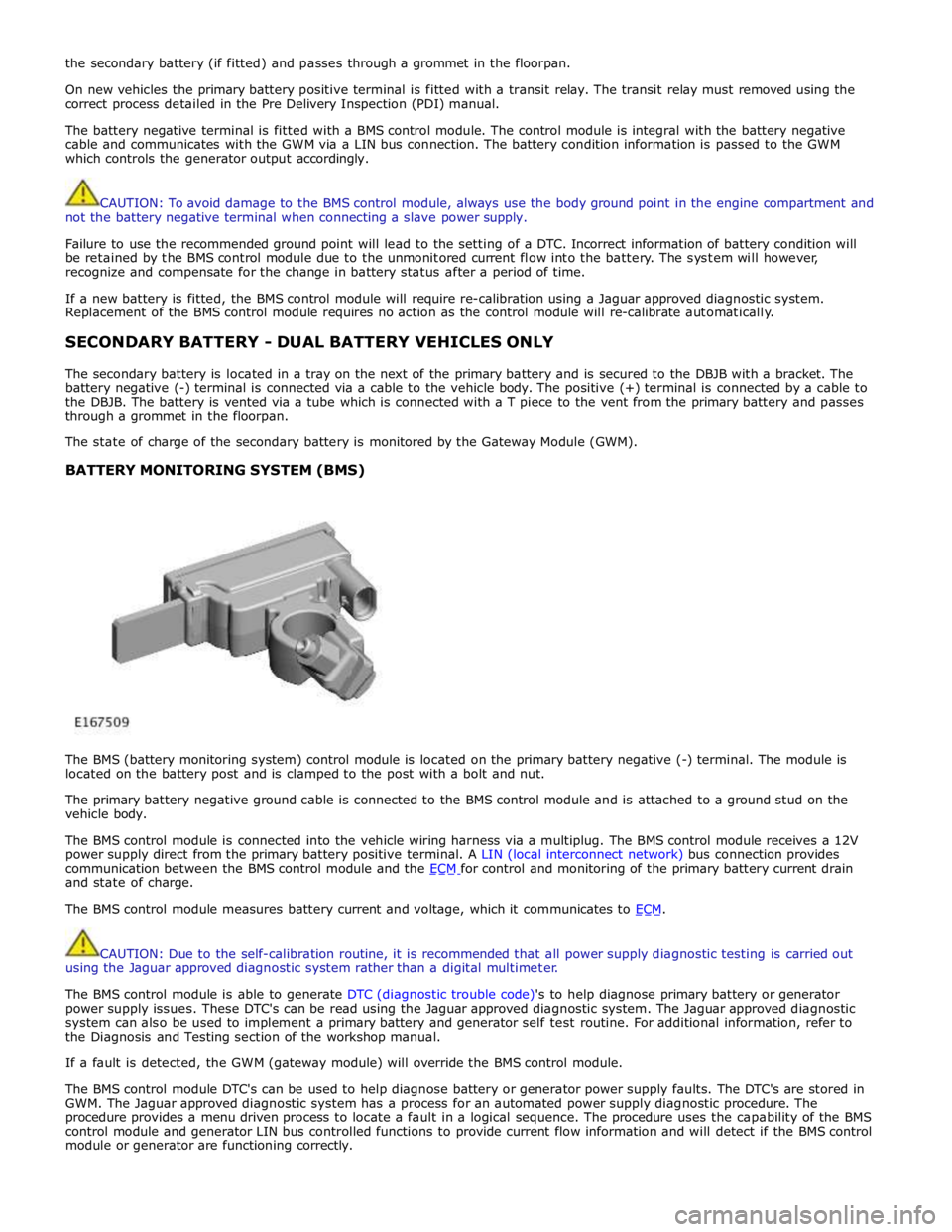
BATTERY MONITORING SYSTEM (BMS)
The BMS (battery monitoring system) control module is located on the primary battery negative (-) terminal. The module is
located on the battery post and is clamped to the post with a bolt and nut.
The primary battery negative ground cable is connected to the BMS control module and is attached to a ground stud on the
vehicle body.
The BMS control module is connected into the vehicle wiring harness via a multiplug. The BMS control module receives a 12V
power supply direct from the primary battery positive terminal. A LIN (local interconnect network) bus connection provides
communication between the BMS control module and the ECM for control and monitoring of the primary battery current drain and state of charge.
The BMS control module measures battery current and voltage, which it communicates to ECM.
CAUTION: Due to the self-calibration routine, it is recommended that all power supply diagnostic testing is carried out
using the Jaguar approved diagnostic system rather than a digital multimeter.
The BMS control module is able to generate DTC (diagnostic trouble code)'s to help diagnose primary battery or generator
power supply issues. These DTC's can be read using the Jaguar approved diagnostic system. The Jaguar approved diagnostic
system can also be used to implement a primary battery and generator self test routine. For additional information, refer to
the Diagnosis and Testing section of the workshop manual.
If a fault is detected, the GWM (gateway module) will override the BMS control module.
The BMS control module DTC's can be used to help diagnose battery or generator power supply faults. The DTC's are stored in
GWM. The Jaguar approved diagnostic system has a process for an automated power supply diagnostic procedure. The
procedure provides a menu driven process to locate a fault in a logical sequence. The procedure uses the capability of the BMS
control module and generator LIN bus controlled functions to provide current flow information and will detect if the BMS control
module or generator are functioning correctly.
Page 1949 of 3039
systems.
A typical example of information transfer is vehicle speed information from the ABS (anti-lock brake system) module used to
control the automatic volume control function. The vehicle speed information from the ABS module is sent on the high speed
CAN network and collected by the instrument panel gateway. The signal is passed to the medium speed CAN network and onto the ICM gateway. The ICM calculates the volume adjustment required. The corrected audio volume level signal is sent on the
MOST network to the IAM or Power amplifier (dependant on vehicle equipment level) for output to the speaker system.
AUDIO SYSTEM USER CONTROLS
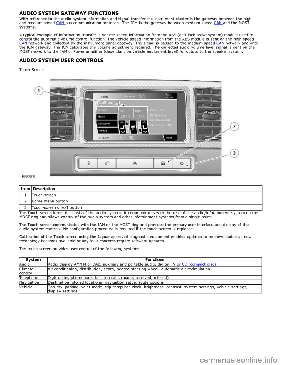
Touch-Screen
Item Description 1 Touch-screen 2 Home menu button 3 Touch-screen on/off button The Touch-screen forms the basis of the audio system. It communicates with the rest of the audio/infotainment system on the
MOST ring and allows control of the audio system and other infotainment systems from a single point.
The Touch-screen communicates with the IAM on the MOST ring and provides the primary user interface and display of the
audio system controls. No configuration procedure is required if the touch-screen is replaced.
Calibration of the Touch-screen using the Jaguar approved diagnostic equipment enables updates to be downloaded as new
technology becomes available or any fault concerns require software updates.
The touch-screen provides user control of the following systems:
System Functions Audio Radio display AM/FM or DAB, auxiliary and portable audio, digital TV or CD (compact disc) Climate
control Air conditioning, distribution, seats, heated steering wheel, automatic air recirculation Telephone Digit dialer, phone book, last ten calls (made, received, missed) Navigation Destination, stored locations, navigation setup, route options Vehicle
Security, parking, valet mode, trip computer, clock, brightness, contrast, system settings, vehicle settings, display settings
Page 1951 of 3039
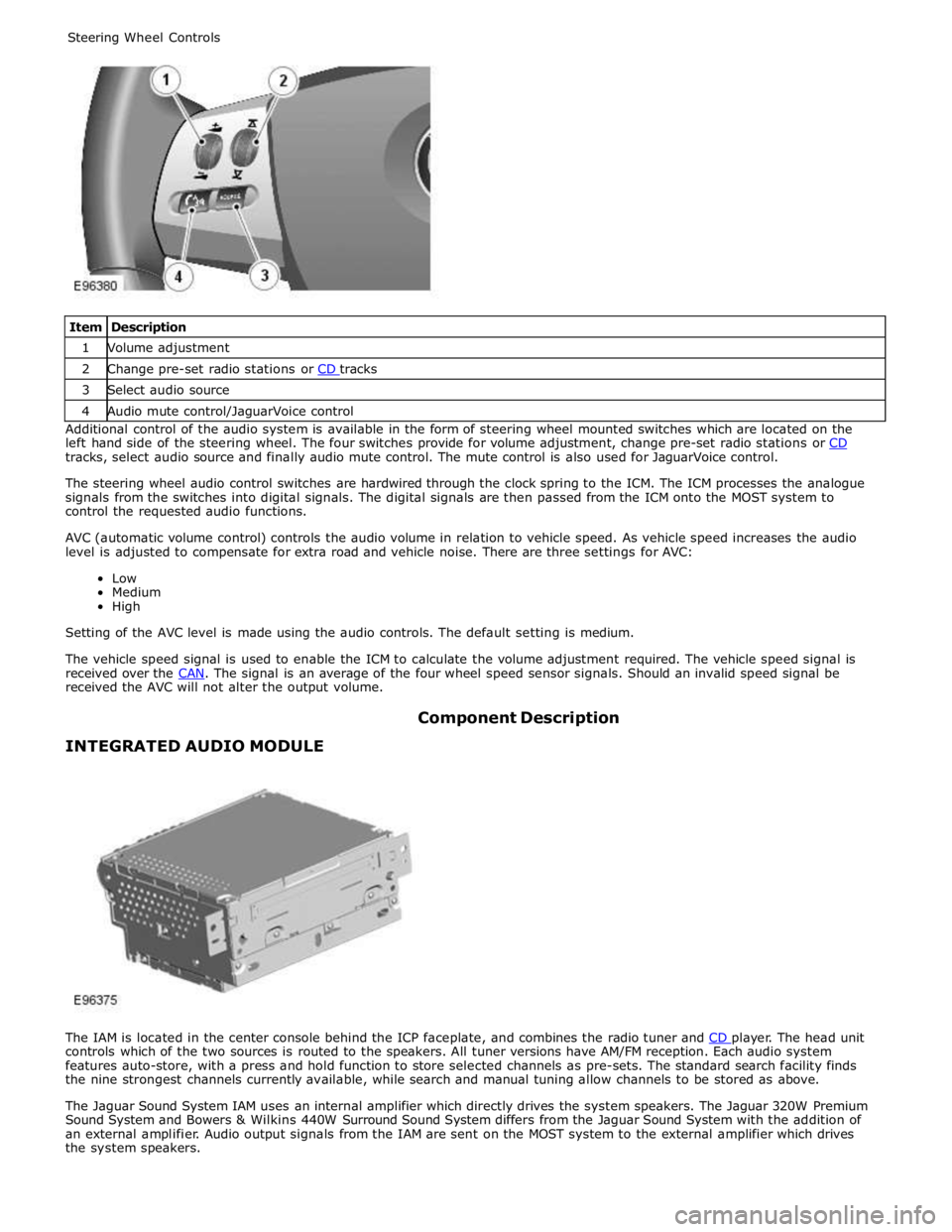
1 Volume adjustment 2 Change pre-set radio stations or CD tracks 3 Select audio source 4 Audio mute control/JaguarVoice control Additional control of the audio system is available in the form of steering wheel mounted switches which are located on the
left hand side of the steering wheel. The four switches provide for volume adjustment, change pre-set radio stations or CD tracks, select audio source and finally audio mute control. The mute control is also used for JaguarVoice control.
The steering wheel audio control switches are hardwired through the clock spring to the ICM. The ICM processes the analogue
signals from the switches into digital signals. The digital signals are then passed from the ICM onto the MOST system to
control the requested audio functions.
AVC (automatic volume control) controls the audio volume in relation to vehicle speed. As vehicle speed increases the audio
level is adjusted to compensate for extra road and vehicle noise. There are three settings for AVC:
Low
Medium
High
Setting of the AVC level is made using the audio controls. The default setting is medium.
The vehicle speed signal is used to enable the ICM to calculate the volume adjustment required. The vehicle speed signal is
received over the CAN. The signal is an average of the four wheel speed sensor signals. Should an invalid speed signal be received the AVC will not alter the output volume.
INTEGRATED AUDIO MODULE Component Description
The IAM is located in the center console behind the ICP faceplate, and combines the radio tuner and CD player. The head unit controls which of the two sources is routed to the speakers. All tuner versions have AM/FM reception. Each audio system
features auto-store, with a press and hold function to store selected channels as pre-sets. The standard search facility finds
the nine strongest channels currently available, while search and manual tuning allow channels to be stored as above.
The Jaguar Sound System IAM uses an internal amplifier which directly drives the system speakers. The Jaguar 320W Premium
Sound System and Bowers & Wilkins 440W Surround Sound System differs from the Jaguar Sound System with the addition of
an external amplifier. Audio output signals from the IAM are sent on the MOST system to the external amplifier which drives
the system speakers.
Page 1953 of 3039
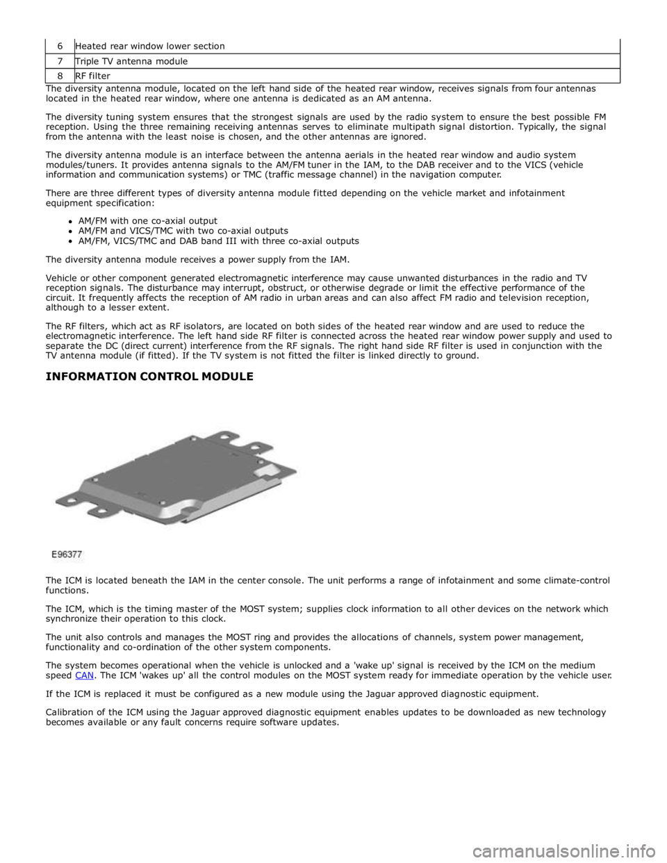
7 Triple TV antenna module 8 RF filter The diversity antenna module, located on the left hand side of the heated rear window, receives signals from four antennas
located in the heated rear window, where one antenna is dedicated as an AM antenna.
The diversity tuning system ensures that the strongest signals are used by the radio system to ensure the best possible FM
reception. Using the three remaining receiving antennas serves to eliminate multipath signal distortion. Typically, the signal
from the antenna with the least noise is chosen, and the other antennas are ignored.
The diversity antenna module is an interface between the antenna aerials in the heated rear window and audio system
modules/tuners. It provides antenna signals to the AM/FM tuner in the IAM, to the DAB receiver and to the VICS (vehicle
information and communication systems) or TMC (traffic message channel) in the navigation computer.
There are three different types of diversity antenna module fitted depending on the vehicle market and infotainment
equipment specification:
AM/FM with one co-axial output
AM/FM and VICS/TMC with two co-axial outputs
AM/FM, VICS/TMC and DAB band III with three co-axial outputs
The diversity antenna module receives a power supply from the IAM.
Vehicle or other component generated electromagnetic interference may cause unwanted disturbances in the radio and TV
reception signals. The disturbance may interrupt, obstruct, or otherwise degrade or limit the effective performance of the
circuit. It frequently affects the reception of AM radio in urban areas and can also affect FM radio and television reception,
although to a lesser extent.
The RF filters, which act as RF isolators, are located on both sides of the heated rear window and are used to reduce the
electromagnetic interference. The left hand side RF filter is connected across the heated rear window power supply and used to
separate the DC (direct current) interference from the RF signals. The right hand side RF filter is used in conjunction with the
TV antenna module (if fitted). If the TV system is not fitted the filter is linked directly to ground.
INFORMATION CONTROL MODULE
The ICM is located beneath the IAM in the center console. The unit performs a range of infotainment and some climate-control
functions.
The ICM, which is the timing master of the MOST system; supplies clock information to all other devices on the network which
synchronize their operation to this clock.
The unit also controls and manages the MOST ring and provides the allocations of channels, system power management,
functionality and co-ordination of the other system components.
The system becomes operational when the vehicle is unlocked and a 'wake up' signal is received by the ICM on the medium
speed CAN. The ICM 'wakes up' all the control modules on the MOST system ready for immediate operation by the vehicle user. If the ICM is replaced it must be configured as a new module using the Jaguar approved diagnostic equipment.
Calibration of the ICM using the Jaguar approved diagnostic equipment enables updates to be downloaded as new technology
becomes available or any fault concerns require software updates.
Page 1957 of 3039

NOTE: When the vehicle DAB radio is first used the system will not receive any digital stations until the auto-tune
function has been completed.
Digital radio channels are organized into groups called ensembles (also known as multiplexes). Some individual channels may
also provide a number of subchannels. For example, if several sports events are being held simultaneously, the channel may
temporarily choose to broadcast each different event on a separate subchannel.
DAB is broadcast across Europe, Canada and parts of Asia. System transmission is via a terrestrial network, on two separate
broadcasting bands:
DAB band-L
DAB band III
The DAB system requires additional components to be added to the audio system. DAB antennas and a receiver are fitted to
allow reception of the service.
Operation of the DAB system is the same as the radio operation with selections made through the touch-screen and ICP to
access and navigate the system functions.
The DAB receiver is a dedicated tuner which is controlled by the ICM on the MOST ring. The receiver processes the signals from
the DAB antennas. Information is transmitted on the MOST ring and processed by the ICM. The processed information is sent
out to the power amplifier or IAM (with internal amplifier) and broadcast through the speaker system.
No configuration procedure is required if the DAB receiver is replaced. Calibration of the DAB receiver using the Jaguar
approved diagnostic equipment enables updates to be downloaded as new technology becomes available or any fault concerns
require software updates.
Digital Audio Broadcasting Antennas
Item Description 1 Roof pod 2 Diversity antenna module The DAB band III antenna is located in the heated rear window and is part of the diversity antenna module circuit. The two
antenna circuits each have a co-axial connection to the DAB module.
DAB signals are transmitted on either DAB band III (174 - 240 MHz) or DAB band-L (1452 - 1492 MHz). Some countries may
only use the band III signals, while others may only use the band-L signals. Some countries use both frequency ranges within
the same geographical area. The type of DAB signal received depends on the vehicle market location.
The DAB antennas are designed with 50 ohm output impedance. The DAB receiver is fitted with 50 ohm fakra II connectors to
ensure compatibility with the antenna. For optimum performance 50 ohm low loss coaxial cable is used between the antenna
and receiver.
Page 1980 of 3039

the roof pod and is shared with the DAB (digital audio broadcasting) band L antenna or satellite radio antenna where fitted.
The roof pod is located externally in a central position towards the rear of the roof.
The GPS antenna is designed with 50 ohm output impedance. The navigation computer is fitted with 50 ohm fakra II connectors to ensure compatibility with the antenna. For optimum performance 50 ohm low loss coaxial cable is used between
the antenna and navigation computer.
It is possible for the GPS antenna to lose the signal from the GPS satellites; In hilly or tree lined areas
Built up areas with tall buildings
In multi storey car parks
In garages
In tunnels
On bridges
During heavy rain or thunderstorms
When the signal is lost the navigation computer will continue to give guidance using memory mapped data from the DVD map until the signal is restored.
TMC/VICS FM Antenna
Data messages for both TMC (traffic message channel) and VICS (vehicle information and communication system) are received
through the FM antennas and diversity antenna module located in the heated rear window.
VICS Beacon Antenna (Japan Only)
The VICS (vehicle information and communication system) beacon antenna receives infra red and RF (radio frequency) traffic
data signals from road side transmitters. The antenna is connected to the navigation computer which incorporates a VICS
(vehicle information and communication system) receiver.
Touch Screen Display
The Touch-screen is the control interface for the following vehicle systems;
System Functions Audio Radio display AM/FM or DAB (digital audio broadcast), auxiliary and portable audio, digital TV or CD Climate
control Air conditioning, distribution, seats, heated steering wheel, automatic air recirculation Telephone Digit dialer, phone book, last ten calls (made, received, missed) www.JagDocs.com
Page 2026 of 3039
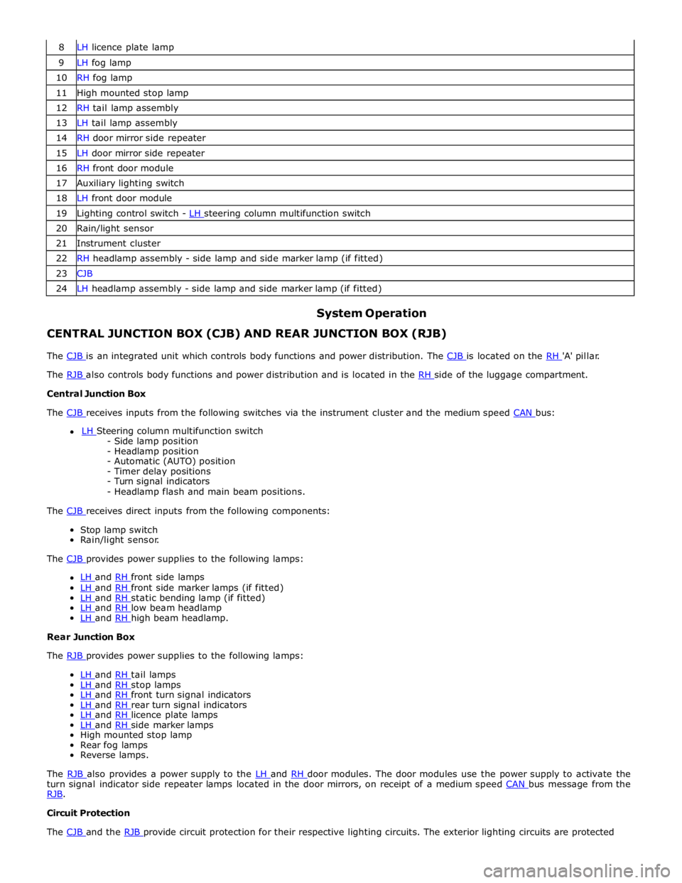
8 LH licence plate lamp 9 LH fog lamp 10 RH fog lamp 11 High mounted stop lamp 12 RH tail lamp assembly 13 LH tail lamp assembly 14 RH door mirror side repeater 15 LH door mirror side repeater 16 RH front door module 17 Auxiliary lighting switch 18 LH front door module 19 Lighting control switch - LH steering column multifunction switch 20 Rain/light sensor 21 Instrument cluster 22 RH headlamp assembly - side lamp and side marker lamp (if fitted) 23 CJB 24 LH headlamp assembly - side lamp and side marker lamp (if fitted)
System Operation CENTRAL JUNCTION BOX (CJB) AND REAR JUNCTION BOX (RJB)
The CJB is an integrated unit which controls body functions and power distribution. The CJB is located on the RH 'A' pillar. The RJB also controls body functions and power distribution and is located in the RH side of the luggage compartment. Central Junction Box
The CJB receives inputs from the following switches via the instrument cluster and the medium speed CAN bus: LH Steering column multifunction switch - Side lamp position
- Headlamp position
- Automatic (AUTO) position
- Timer delay positions
- Turn signal indicators
- Headlamp flash and main beam positions.
The CJB receives direct inputs from the following components: Stop lamp switch
Rain/light sensor.
The CJB provides power supplies to the following lamps:
LH and RH front side lamps LH and RH front side marker lamps (if fitted) LH and RH static bending lamp (if fitted) LH and RH low beam headlamp LH and RH high beam headlamp. Rear Junction Box
The RJB provides power supplies to the following lamps:
LH and RH tail lamps LH and RH stop lamps LH and RH front turn signal indicators LH and RH rear turn signal indicators LH and RH licence plate lamps LH and RH side marker lamps High mounted stop lamp
Rear fog lamps
Reverse lamps.
The RJB also provides a power supply to the LH and RH door modules. The door modules use the power supply to activate the turn signal indicator side repeater lamps located in the door mirrors, on receipt of a medium speed CAN bus message from the RJB. Circuit Protection
The CJB and the RJB provide circuit protection for their respective lighting circuits. The exterior lighting circuits are protected
Page 2124 of 3039
The battery backed sounder is disconnected (partial trigger only).
The vehicle battery is disconnected on a vehicle fitted with a battery backed sounder (partial trigger only).
The inclination sensor detects a change in vehicle attitude.
The intrusion detection module detects movement within the cabin.
Door Modules Component Description
The door modules provide the interface between the door latch-motors, the door latch-switches and the CJB. The door modules
provide door switch status information and enable the door latch-motors on request from the CJB or the keyless vehicle
module.
Keyless Vehicle Module
The keyless vehicle module interfaces with the Central locking, Radio Frequency (RF) receiver and collects RF signal information
which is transmitted from the Smart Key. This information is translated into commands which are passed on the medium speed
CAN bus to the:
CJB,
RJB,
door modules, and
instrument cluster.
The keyless vehicle module also monitors:
2 interior antennae,
1 luggage compartment antenna,
a rear bumper antenna, and
4 door handle antennae if the passive entry system is fitted.
On vehicles with passive entry, the additional fast latch motors are controlled via the keyless vehicle module and the locking
status is passed to the CJB on the medium speed CAN bus.
Instrument Cluster
The instrument cluster controls the alarm indicator, and in conjunction with the ECM (engine control module), the engine
immobilization. The ECM controls the engine crank and fuel functions and the instrument cluster processes the valid
transponder information.
Alarm Indicator
The alarm indicator is a LED (light emitting diode) located in the body of the sunload/light sensor. When the ignition is off the
indicator gives a visual indication of the active anti-theft system to show if the alarm system is active or not active. Operation
of the alarm indicator is controlled by the instrument cluster which varies the flash rate of the LED to indicate the system
status of the alarm and the immobilization systems.
When the ignition is on, the indicator provides a visual indication of the status of the passive anti-theft (engine
immobilization) system. If the immobilization system is operating correctly, the LED will be illuminated for 3 seconds at
ignition on and then extinguish. If a fault exists in the immobilization system, the LED will be either permanently illuminated
or flashing for 60 seconds. This indicates that a fault exists and fault code has been recorded. After the 60 second period the
LED will flash at different frequencies which indicate the nature of the fault.
Refer to: Anti-Theft - Passive (419-01B Anti-Theft - Passive, Description and Operation).
Passive Anti-Theft Horn
The passive anti-theft horn is hardwired to the CJB which activates the horn when the alarm is triggered.
Battery Backed Sounder
Operation of the battery backed sounder is controlled by the CJB on the LIN bus. The sounder is also connected with a
permanent battery supply via the CJB. An integral, rechargeable battery powers the sounder if the battery power supply from
the CJB is interrupted.
Dependant on vehicle, a incitation sensor is incorporated into the battery backed sounder, to monitor vehicle attitude, see
Inclination Sensor.
Inclination Sensor
The CJB monitors the inclination sensor and will activate the alarm system if the vehicle is being raised.
Intrusion Detection Module
The intrusion detection module comprises an ultrasonic sound wave sensor which monitors the vehicle's interior.
The intrusion detection module is activated with volumetric mode which in turn is enabled when the vehicle is double locked.
The vehicle can be locked and alarmed with the module de-activated if a pet is to be left in the vehicle for example by single-
Page 2143 of 3039
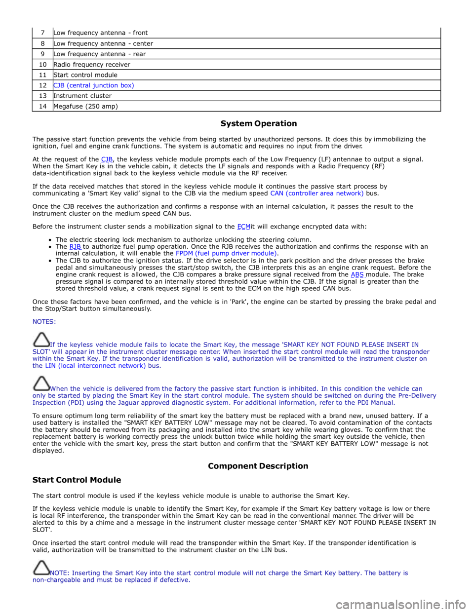
7 Low frequency antenna - front 8 Low frequency antenna - center 9 Low frequency antenna - rear 10 Radio frequency receiver 11 Start control module 12 CJB (central junction box) 13 Instrument cluster 14 Megafuse (250 amp)
System Operation
The passive start function prevents the vehicle from being started by unauthorized persons. It does this by immobilizing the
ignition, fuel and engine crank functions. The system is automatic and requires no input from the driver.
At the request of the CJB, the keyless vehicle module prompts each of the Low Frequency (LF) antennae to output a signal. When the Smart Key is in the vehicle cabin, it detects the LF signals and responds with a Radio Frequency (RF)
data-identification signal back to the keyless vehicle module via the RF receiver.
If the data received matches that stored in the keyless vehicle module it continues the passive start process by
communicating a 'Smart Key valid’ signal to the CJB via the medium speed CAN (controller area network) bus.
Once the CJB receives the authorization and confirms a response with an internal calculation, it passes the result to the
instrument cluster on the medium speed CAN bus.
Before the instrument cluster sends a mobilization signal to the ECMit will exchange encrypted data with: The electric steering lock mechanism to authorize unlocking the steering column.
The RJB to authorize fuel pump operation. Once the RJB receives the authorization and confirms the response with an internal calculation, it will enable the FPDM (fuel pump driver module).
The CJB to authorize the ignition status. If the drive selector is in the park position and the driver presses the brake
pedal and simultaneously presses the start/stop switch, the CJB interprets this as an engine crank request. Before the
engine crank request is allowed, the CJB compares a brake pressure signal received from the ABS module. The brake pressure signal is compared to an internally stored threshold value within the CJB. If the signal is greater than the
stored threshold value, a crank request signal is sent to the ECM on the high speed CAN bus.
Once these factors have been confirmed, and the vehicle is in 'Park', the engine can be started by pressing the brake pedal and
the Stop/Start button simultaneously.
NOTES:
If the keyless vehicle module fails to locate the Smart Key, the message 'SMART KEY NOT FOUND PLEASE INSERT IN
SLOT' will appear in the instrument cluster message center. When inserted the start control module will read the transponder
within the Smart Key. If the transponder identification is valid, authorization will be transmitted to the instrument cluster on
the LIN (local interconnect network) bus.
When the vehicle is delivered from the factory the passive start function is inhibited. In this condition the vehicle can
only be started by placing the Smart Key in the start control module. The system should be switched on during the Pre-Delivery
Inspection (PDI) using the Jaguar approved diagnostic system. For additional information, refer to the PDI Manual.
To ensure optimum long term reliability of the smart key the battery must be replaced with a brand new, unused battery. If a
used battery is installed the "SMART KEY BATTERY LOW" message may not be cleared. To avoid contamination of the contacts
the battery should be removed from its packaging and installed into the smart key while wearing gloves. To confirm that the
replacement battery is working correctly press the unlock button twice while holding the smart key outside the vehicle, then
enter the vehicle with the smart key, press the start button and confirm that the "SMART KEY BATTERY LOW" message is not
displayed.
Start Control Module Component Description
The start control module is used if the keyless vehicle module is unable to authorise the Smart Key.
If the keyless vehicle module is unable to identify the Smart Key, for example if the Smart Key battery voltage is low or there
is local RF interference, the transponder within the Smart Key can be read in the conventional manner. The driver will be
alerted to this by a chime and a message in the instrument cluster message center 'SMART KEY NOT FOUND PLEASE INSERT IN
SLOT'.
Once inserted the start control module will read the transponder within the Smart Key. If the transponder identification is
valid, authorization will be transmitted to the instrument cluster on the LIN bus.
NOTE: Inserting the Smart Key into the start control module will not charge the Smart Key battery. The battery is
non-chargeable and must be replaced if defective.
Page 2145 of 3039
Anti-Theft - Passive (Description and Operation), Anti-Theft - Passive (Description and Operation).
Inspection and Verification
Anti-theft - Passive
The best method to confirm the correct operation of the Passive Anti-Theft System (PATS) is to check the LED (located in the
center of the instrument panel). The LED should illuminate solid for 3 seconds, when the ignition status is set to ON, and then
extinguish. This validates all PATS functions (i.e. the key transponder matches a stored key code, the challenge/response
sequence between the respective modules was successful resulting in the EMS being enabled).
Ignition fails to operate
Check that the smart key is located within the vehicle interior, and that it is the correct one for the vehicle.
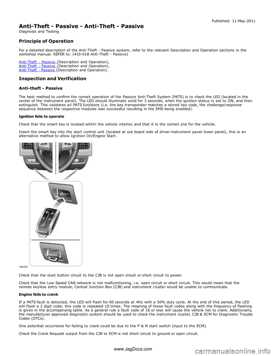
Insert the smart key into the start control unit (located at out board side of driver instrument panel lower panel), this is an
alternative method to allow Ignition On/Engine Start.
Check that the start button circuit to the CJB is not open circuit or short circuit to power.
Check that the Low Speed CAN network is not malfunctioning, i.e. open circuit or short circuit. This would mean that the
remote keyless entry module, Central Junction Box (CJB) and instrument cluster would be unable to communicate.
Engine fails to crank
If a PATS fault is detected, the LED will flash for 60 seconds at 4Hz with a 50% duty cycle. At the end of this period, the LED
will flash a 2 digit code; this code is repeated 10 times. The meaning of these fault codes along with the frequency of flashing
is given in the accompanying table. As a general rule a fault code of 16 or less will cause the vehicle not to crank. Additionally,
the manufacturer approved diagnostic system should be used to check the instrument cluster, CJB & ECM for Diagnostic Trouble
Codes (DTCs).
One potential occurrence for failing to crank could be due to the P & N start switch (input to the ECM).
Check the Crank Request output from the CJB to ECM is not short circuit to ground or open circuit. www.JagDocs.com