engine coolant JAGUAR XFR 2010 1.G Owner's Manual
[x] Cancel search | Manufacturer: JAGUAR, Model Year: 2010, Model line: XFR, Model: JAGUAR XFR 2010 1.GPages: 3039, PDF Size: 58.49 MB
Page 1125 of 3039

- Megafuse fixing nuts
Engine junction box
- Megafuse
- Megafuse fixing nuts
- Fuses
- Engine control module relay Were any circuits or wiring short circuit to ground, short circuit to power, open circuit, high resistance or any
connectors damaged from water ingress, pin damage and/or corrosion?
Yes
Rectify as required
No
Proceed to the next step. A9 'Cooling fan validation procedure' A9: COOLING FAN VALIDATION PROCEDURE 1 Ensure the hood is closed 2 Allow vehicle to idle 3 Switch ON air conditioning and set to lowest temperature and highest fan speed 4 Allow vehicle to reach operating temperature (approximately 90 degrees C). Using the manufacturer approved diagnostic system monitor datalogger signals – Engine Coolant Temperature (0XF405) -and -
Electric Fan PWM Control - Commanded (0X03F9) - as the engine coolant temperature reaches
operating temperature the fan speed should also increase between the values of 9 and 90% Did the cooling fan rotate at increasing speed as engine coolant temperature increased?
Yes
Return vehicle to customer
No
Contact dealer technical support DTC Index
For a list of diagnostic trouble codes (DTCs) that could be logged on this vehicle, please refer to Section 100-00.
REFER to: Electronic Engine Controls (303-14D Electronic Engine Controls - V8 S/C 5.0L Petrol, Diagnosis and Testing). www.JagDocs.com
Page 1126 of 3039
Published: 11-May-2011
Engine Cooling - V8 5.0L Petrol/V8 S/C 5.0L Petrol - Cooling System Draining
and Vacuum Filling
General Procedures
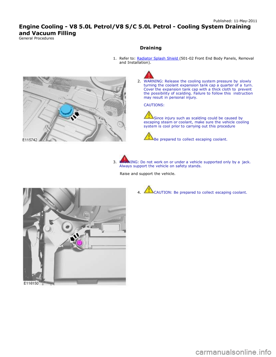
Draining
1. Refer to: Radiator Splash Shield (501-02 Front End Body Panels, Removal and Installation).
2. WARNING: Release the cooling system pressure by slowly
turning the coolant expansion tank cap a quarter of a turn.
Cover the expansion tank cap with a thick cloth to prevent
the possibility of scalding. Failure to follow this instruction
may result in personal injury.
CAUTIONS:
Since injury such as scalding could be caused by
escaping steam or coolant, make sure the vehicle cooling
system is cool prior to carrying out this procedure
Be prepared to collect escaping coolant.
3. WARNING: Do not work on or under a vehicle supported only by a jack.
Always support the vehicle on safety stands.
Raise and support the vehicle.
4. CAUTION: Be prepared to collect escaping coolant.
Page 1127 of 3039
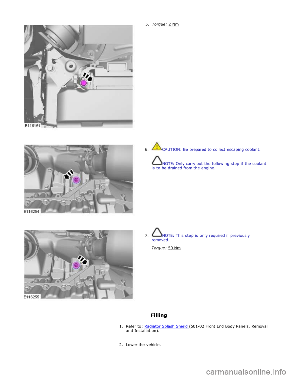
5. Torque: 2 Nm 6. CAUTION: Be prepared to collect escaping coolant.
NOTE: Only carry out the following step if the coolant
is to be drained from the engine.
7. NOTE: This step is only required if previously
removed.
Torque: 50 Nm
Filling
1. Refer to: Radiator Splash Shield (501-02 Front End Body Panels, Removal and Installation).
2. Lower the vehicle.
Page 1129 of 3039
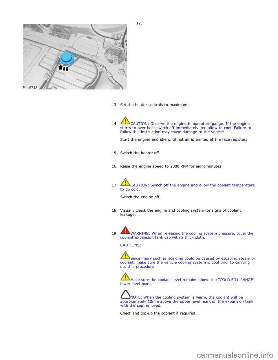
12.
13.
Set the heater controls to maximum.
14. CAUTION: Observe the engine temperature gauge. If the engine
starts to over-heat switch off immediately and allow to cool. Failure to
follow this instruction may cause damage to the vehicle
Start the engine and idle until hot air is emited at the face registers.
15. Switch the heater off.
16. Raise the engine speed to 2000 RPM for eight minutes.
17. CAUTION: Switch off the engine and allow the coolant temperature
to go cold.
Switch the engine off.
18. Visually check the engine and cooling system for signs of coolant
leakage.
19. WARNING: When releasing the cooling system pressure, cover the
coolant expansion tank cap with a thick cloth.
CAUTIONS:
Since injury such as scalding could be caused by escaping steam or
coolant, make sure the vehicle cooling system is cool prior to carrying
out this procedure
Make sure the coolant level remains above the "COLD FILL RANGE"
lower level mark.
NOTE: When the cooling system is warm, the coolant will be
approximately 10mm above the upper level mark on the expansion tank
with the cap removed.
Check and top-up the coolant if required.
Page 1130 of 3039
Published: 14-Feb-2013
Engine Cooling - V8 5.0L Petrol/V8 S/C 5.0L Petrol - Cooling System Partial Draining, Filling and Bleeding V8 S/C 5.0L Petrol
General Procedures
Draining
1. WARNING: Make sure to support the vehicle with axle stands.
Raise and support the vehicle.
2. Refer to: Radiator Splash Shield (501-02 Front End Body Panels, Removal and Installation).
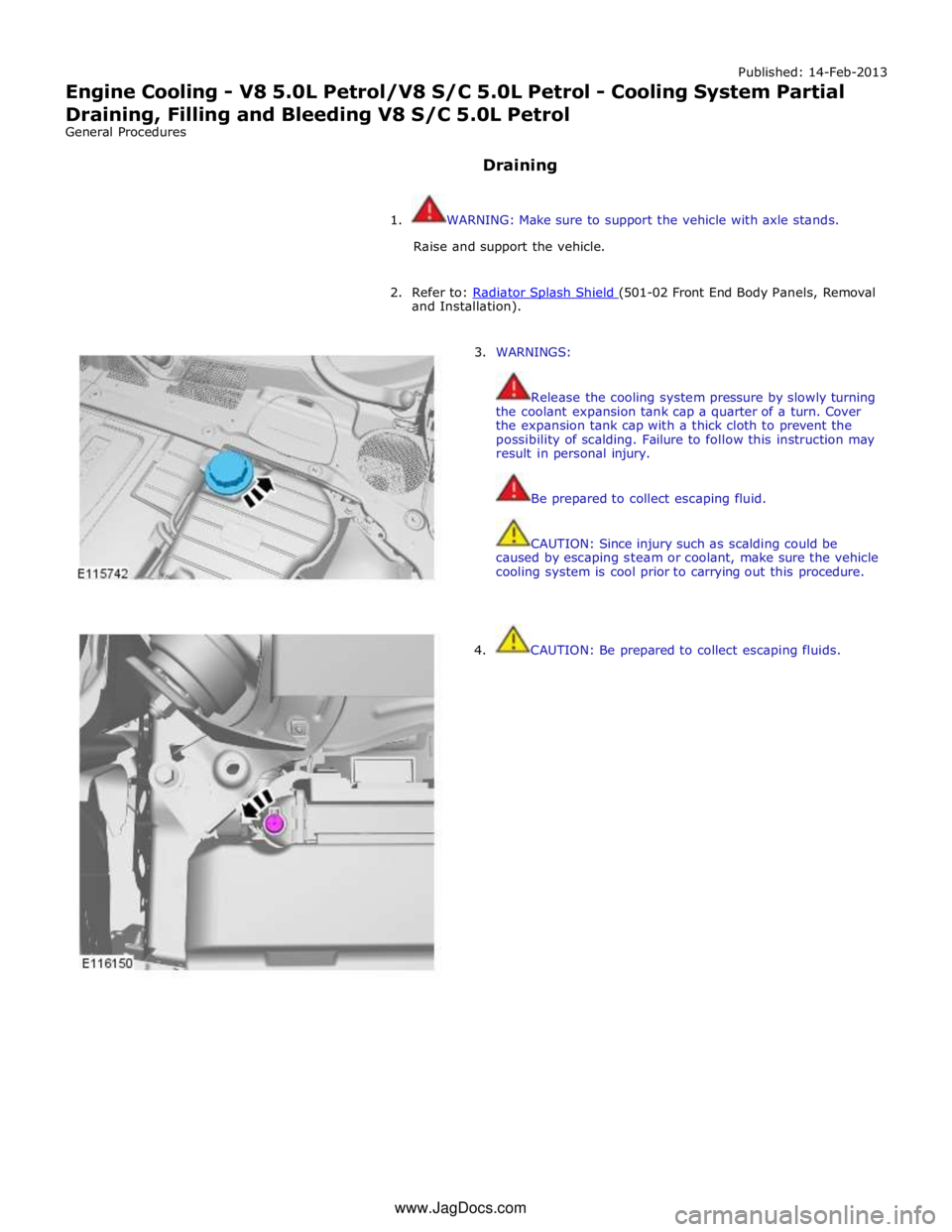
3. WARNINGS:
Release the cooling system pressure by slowly turning
the coolant expansion tank cap a quarter of a turn. Cover
the expansion tank cap with a thick cloth to prevent the
possibility of scalding. Failure to follow this instruction may
result in personal injury.
Be prepared to collect escaping fluid.
CAUTION: Since injury such as scalding could be
caused by escaping steam or coolant, make sure the vehicle
cooling system is cool prior to carrying out this procedure.
4. CAUTION: Be prepared to collect escaping fluids. www.JagDocs.com
Page 1132 of 3039
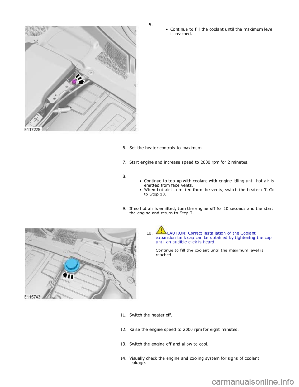
5.
Continue to fill the coolant until the maximum level
is reached.
6. Set the heater controls to maximum.
7. Start engine and increase speed to 2000 rpm for 2 minutes.
8.
Continue to top-up with coolant with engine idling until hot air is
emitted from face vents.
When hot air is emitted from the vents, switch the heater off. Go
to Step 10.
9. If no hot air is emitted, turn the engine off for 10 seconds and the start
the engine and return to Step 7.
10. CAUTION: Correct installation of the Coolant
expansion tank cap can be obtained by tightening the cap
until an audible click is heard.
Continue to fill the coolant until the maximum level is
reached.
11. Switch the heater off.
12. Raise the engine speed to 2000 rpm for eight minutes.
13. Switch the engine off and allow to cool.
14. Visually check the engine and cooling system for signs of coolant
leakage.
Page 1134 of 3039
Published: 14-Feb-2013
Engine Cooling - V8 5.0L Petrol/V8 S/C 5.0L Petrol - Cooling System Draining,
Filling and Bleeding V8 S/C 5.0L Petrol
General Procedures
Draining
1. WARNING: Make sure to support the vehicle with axle stands.
Raise and support the vehicle.
2. Refer to: Secondary Bulkhead Center Panel (501-02 Front End Body Panels, Removal and Installation).
3. Refer to: Air Deflector (501-02 Front End Body Panels, Removal and Installation).
4. Refer to: Radiator Splash Shield (501-02 Front End Body Panels, Removal and Installation).
5. WARNINGS:
Release the cooling system pressure by slowly turning
the coolant expansion tank cap a quarter of a turn. Cover
the expansion tank cap with a thick cloth to prevent the
possibility of scalding. Failure to follow this instruction may
result in personal injury.
Be prepared to collect escaping fluid.
CAUTION: Since injury such as scalding could be
caused by escaping steam or coolant, make sure the vehicle
cooling system is cool prior to carrying out this procedure.
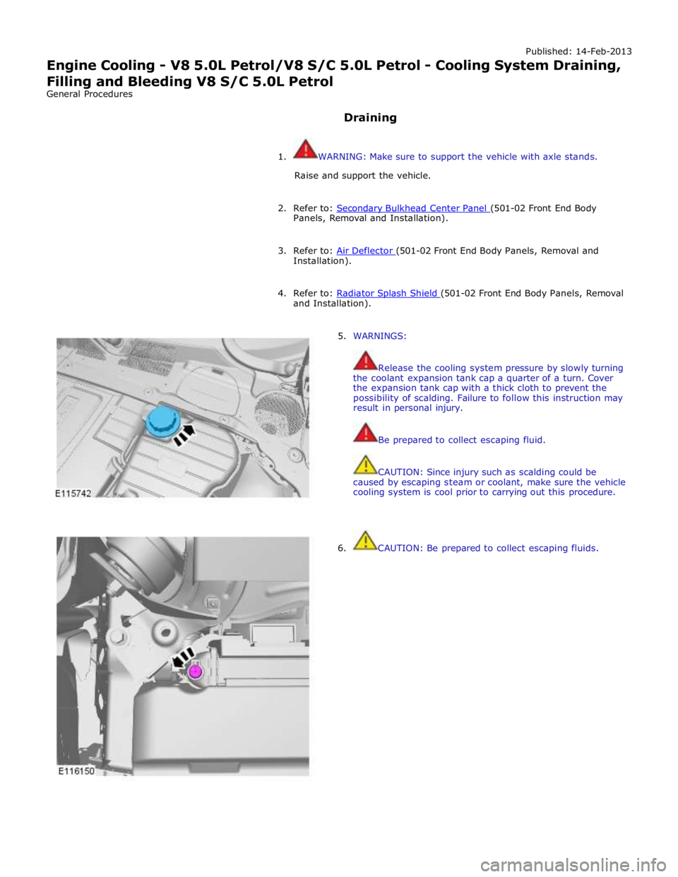
6. CAUTION: Be prepared to collect escaping fluids.
Page 1138 of 3039
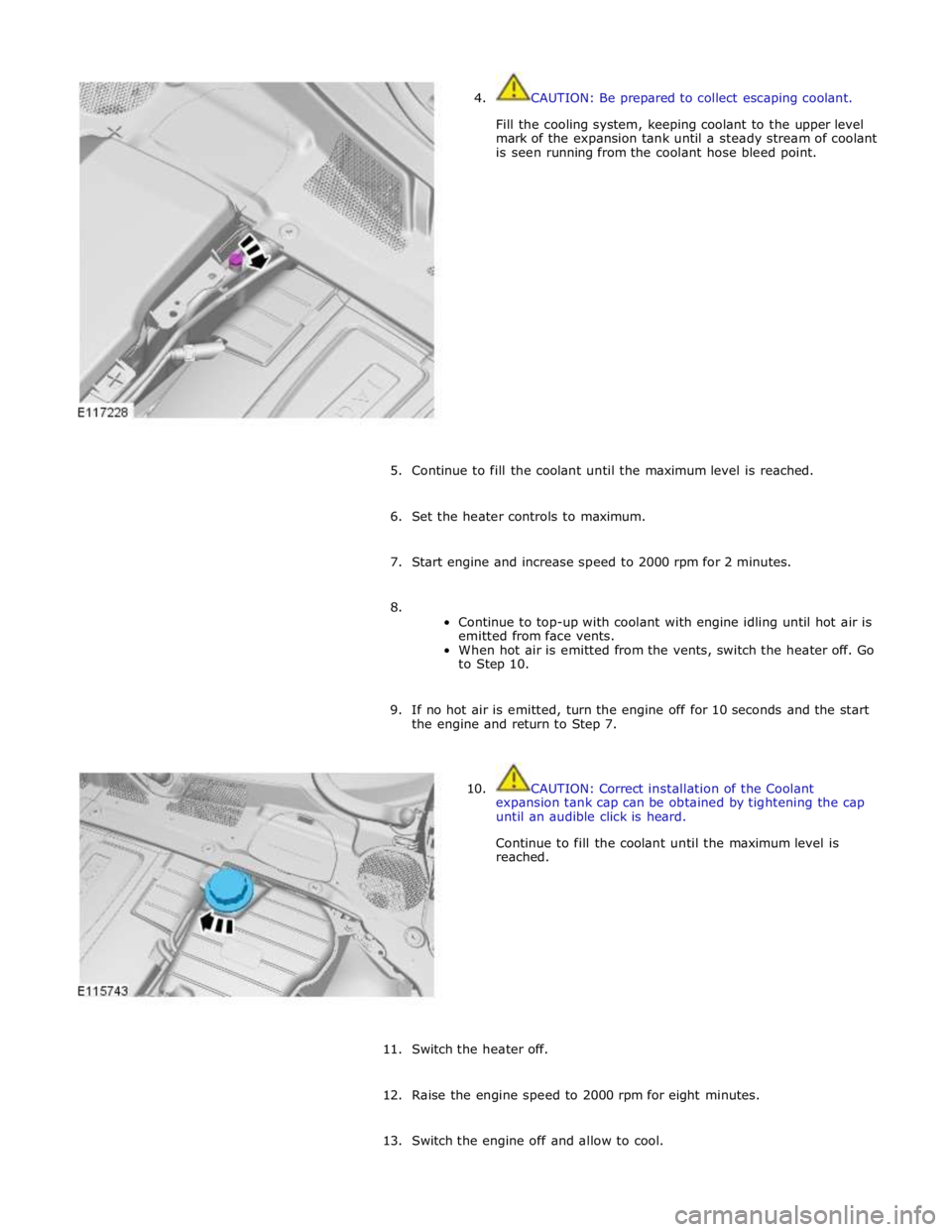
4. CAUTION: Be prepared to collect escaping coolant.
Fill the cooling system, keeping coolant to the upper level
mark of the expansion tank until a steady stream of coolant
is seen running from the coolant hose bleed point.
5. Continue to fill the coolant until the maximum level is reached.
6. Set the heater controls to maximum.
7. Start engine and increase speed to 2000 rpm for 2 minutes.
8.
Continue to top-up with coolant with engine idling until hot air is
emitted from face vents.
When hot air is emitted from the vents, switch the heater off. Go
to Step 10.
9. If no hot air is emitted, turn the engine off for 10 seconds and the start
the engine and return to Step 7.
10. CAUTION: Correct installation of the Coolant
expansion tank cap can be obtained by tightening the cap
until an audible click is heard.
Continue to fill the coolant until the maximum level is
reached.
11. Switch the heater off.
12. Raise the engine speed to 2000 rpm for eight minutes.
13. Switch the engine off and allow to cool.
Page 1139 of 3039
14. Visually check the engine and cooling system for signs of coolant
leakage.
15. WARNING: When releasing the cooling system pressure, cover the
coolant expansion tank cap with a thick cloth.
CAUTIONS:
Since injury such as scalding could be caused by escaping steam or
coolant, make sure the vehicle cooling system is cool prior to carrying
out this procedure.
Make sure the coolant level remains above the "COLD FILL RANGE"
lower level mark.
NOTE: When the cooling system is warm, the coolant will be
approximately 10mm above the upper level mark on the expansion tank
with the cap removed.
Check and top-up the coolant system as required when cool.
16. Refer to: Air Deflector (501-02 Front End Body Panels, Removal and Installation).
17. Refer to: Radiator Splash Shield (501-02 Front End Body Panels, Removal and Installation).
18. Refer to: Secondary Bulkhead Center Panel (501-02 Front End Body Panels, Removal and Installation).
Page 1140 of 3039
Published: 19-Nov-2013
Engine Cooling - V8 5.0L Petrol/V8 S/C 5.0L Petrol - Auxiliary Radiator
Removal and Installation
Removal
NOTE: Removal steps in this procedure may contain installation details.
1. Refer to: Battery Disconnect and Connect (414-01 Battery, Mounting and Cables, General Procedures).
2. Refer to: Air Cleaner RH (303-12C Intake Air Distribution and Filtering - V8 5.0L Petrol, Removal and Installation).
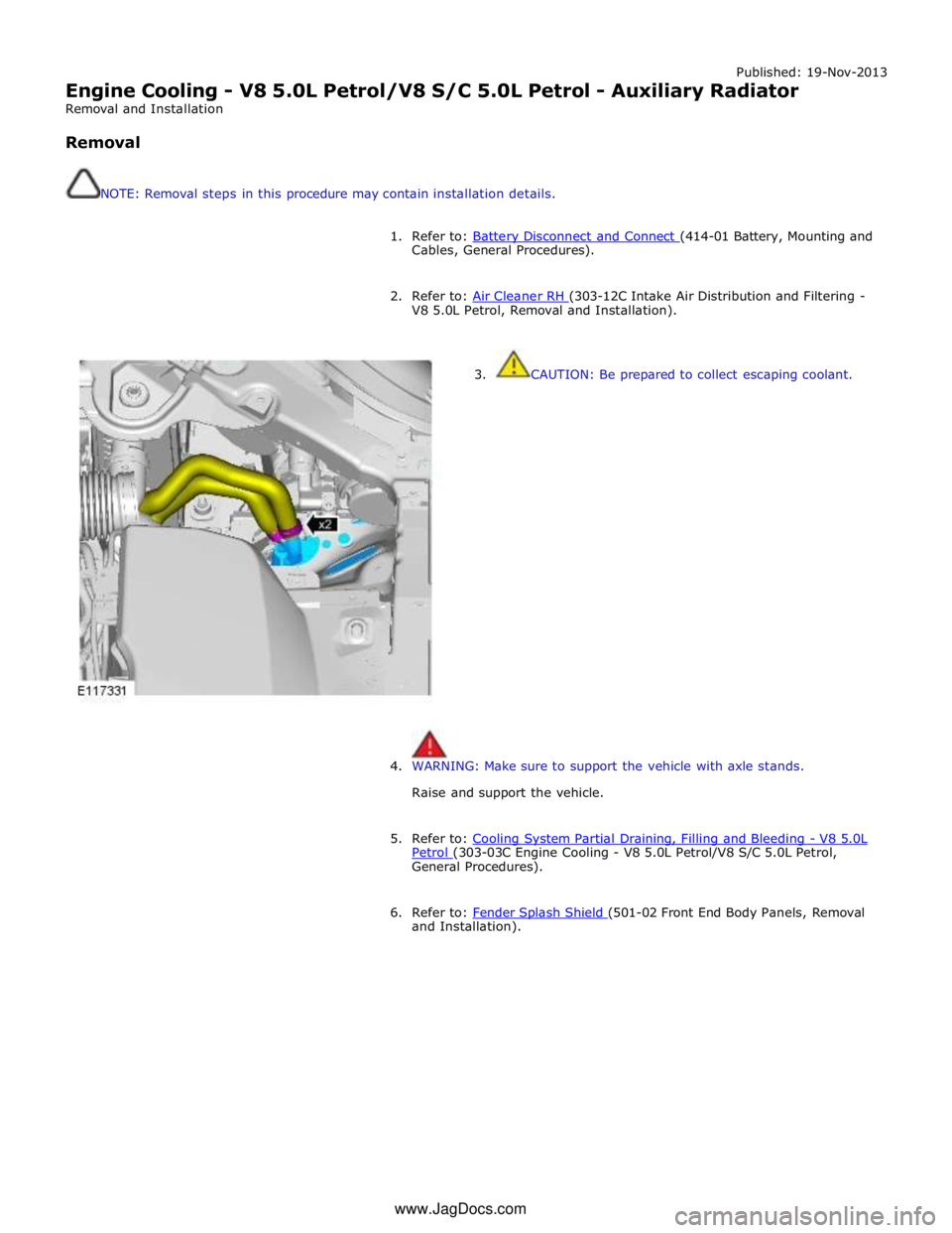
3. CAUTION: Be prepared to collect escaping coolant.
4. WARNING: Make sure to support the vehicle with axle stands.
Raise and support the vehicle.
5. Refer to: Cooling System Partial Draining, Filling and Bleeding - V8 5.0L Petrol (303-03C Engine Cooling - V8 5.0L Petrol/V8 S/C 5.0L Petrol, General Procedures).
6. Refer to: Fender Splash Shield (501-02 Front End Body Panels, Removal and Installation). www.JagDocs.com