steering JAGUAR XFR 2010 1.G Owner's Manual
[x] Cancel search | Manufacturer: JAGUAR, Model Year: 2010, Model line: XFR, Model: JAGUAR XFR 2010 1.GPages: 3039, PDF Size: 58.49 MB
Page 194 of 3039

DTC Description Possible Causes Action B1C33-14
Steering Column Tilt
Feedback Signal - Circuit
short to ground or open
Steering column tilt
feedback signal circuit -
short to ground, open circuit
Carry out any pinpoint tests associated with this
DTC using the manufacturer approved diagnostic
system. Refer to the electrical circuit diagrams
and check steering column tilt feedback signal
circuit for short to ground, open circuit B1C34-77
Steering Column Telescope Solenoid -
Commanded position
not reachable
REACH axis fails to move
minimum distance within
allotted time period. Motion
may have been prohibited
due to motor jamming,
stalling or solenoid pin not
engaging
Check for restricted/jammed steering column
motor mechanism. Refer to the electrical circuit
diagrams and check steering column motor
UP/IN, DOWN/OUT circuit for short, open circuit B1C34-94
Steering Column Telescope Solenoid -
Unexpected operation
REACH axis moves when it
has not been commanded
to. Motion may have
occurred due to solenoid pin
not disengaging or
mechanism has been
jammed on, whilst TILT axis
has been commanded to
move
Check for stuck/jammed solenoid/switch. Refer
to the electrical circuit diagrams and check
steering column motor UP/IN, DOWN/OUT circuit
for short, open circuit B1C35-12
Steering Column Telescope Feedback
Signal - Circuit short to
battery
Steering column TELE
feedback signal circuit -
short to power
Refer to the electrical circuit diagrams and check
steering column TELE feedback signal circuit for
short to power B1C35-14
Steering Column Telescope Feedback
Signal - Circuit short to
ground or open
Steering column TELE
feedback signal circuit -
short to ground, open circuit
Carry out any pinpoint tests associated with this
DTC using the manufacturer approved diagnostic
system. Refer to the electrical circuit diagrams
and check steering column TELE feedback signal
circuit for short to ground, open circuit B1C36-11
Steering Column Tilt/Telescope Switch -
Circuit short to ground
Steering column adjust
switch circuit - short to
ground
Refer to the electrical circuit diagrams and check
steering column adjust switch circuit for short to
ground B1C48-11
Flash to Pass Switch -
Circuit short to ground
Main beam flash switch
circuit - short to ground
Refer to the electrical circuit diagrams and check
main beam flash switch circuit for short to
ground B1C48-15
Flash to Pass Switch -
Circuit short to battery
or open
Main beam flash switch
circuit - short to power,
open circuit
Carry out any pinpoint tests associated with this
DTC using the manufacturer approved diagnostic
system. Refer to the electrical circuit diagrams
and check main beam flash switch circuit for
short to power, open circuit B1C53-11
Front Wiper Intermittent
Data - Circuit short to
ground
Intermittent wipe switch
circuit - short to ground
Refer to the electrical circuit diagrams and check
intermittent wipe switch circuit for short to
ground B1C53-15
Front Wiper Intermittent
Data - Circuit short to
battery or open
Intermittent wipe switch
circuit - short to power,
open circuit
Carry out any pinpoint tests associated with this
DTC using the manufacturer approved diagnostic
system. Refer to the electrical circuit diagrams
and check intermittent wipe switch circuit for
short to power, open circuit B1D36-11 Turn Indicator Switch -
Circuit short to ground
Direction indicator switch
circuit - short to ground
Refer to the electrical circuit diagrams and check
direction indicator switch circuit for short to
ground B1D36-15 Turn Indicator Switch -
Circuit short to battery
or open
Direction indicator switch
circuit - short to power,
open circuit
Carry out any pinpoint tests associated with this
DTC using the manufacturer approved diagnostic
system. Refer to the electrical circuit diagrams
and check direction indicator switch circuit for
short to power, open circuit
Page 195 of 3039

DTC Description Possible Causes Action B1D37-11
Wiper Switch
Connection Circuit -
Circuit short to ground
Flick wipe switch circuit -
short to ground
Refer to the electrical circuit diagrams and check
flick wipe switch circuit for short to ground B1D37-15
Wiper Switch
Connection Circuit -
Circuit short to battery
or open
Flick wipe switch circuit -
short to power, open circuit
Carry out any pinpoint tests associated with this
DTC using the manufacturer approved diagnostic
system. Refer to the electrical circuit diagrams
and check flick wipe switch circuit for short to
power, open circuit C1110-64
Power steering
Calibration Data - Signal
plausibility failure
Invalid VAPS curve loaded
Re-configure the instrument cluster as new to
download VAPS curve data P0635-11
Power Steering Control
Circuit - Circuit short to
ground
VAPS ignition supply circuit
- short to ground
Refer to the electrical circuit diagrams and check
VAPS ignition supply circuit for short to ground P0635-12
Power Steering Control
Circuit - Circuit short to
battery
VAPS ignition supply circuit
- short to power
Refer to the electrical circuit diagrams and check
VAPS ignition supply circuit for short to power P0635-13
Power Steering Control
Circuit - Circuit open
VAPS ignition supply circuit
- open circuit
Refer to the electrical circuit diagrams and check
VAPS ignition supply circuit for open circuit P0635-22
Power Steering Control
Circuit - Signal
amplitude > maximum
First valid received speed
value above threshold
Check ABS module for DTCs and refer to relevant
DTC Index P0635-44
Power Steering Control
Circuit - Data memory
failure
Data memory failure
Re-configure the instrument cluster as new to
download VAPS curve data U0001-88
High Speed CAN
Communication Bus -
Bus off
Bus Off
Carry out any pinpoint tests associated with this
DTC using the manufacturer approved diagnostic
system. Carry out CAN network integrity test
using the manufacturer approved diagnostic
system. Refer to the electrical circuit diagrams
and check HS CAN network to instrument cluster U0010-88
Medium Speed CAN
Communication Bus -
Bus off
Bus Off
Carry out any pinpoint tests associated with this
DTC using the manufacturer approved diagnostic
system. Carry out CAN network integrity test
using the manufacturer approved diagnostic
system. Refer to the electrical circuit diagrams
and check MS CAN network to instrument cluster U0100-00
Lost Communication
With ECM/PCM “A” - No
sub type information
Loss of CAN communication
with ECM
Carry out any pinpoint tests associated with this
DTC using the manufacturer approved diagnostic
system. Check ECM for DTCs and refer to the
relevant DTC Index U0101-00
Lost Communication
with TCM - No sub type
information
Loss of CAN communication
with TCM
Carry out any pinpoint tests associated with this
DTC using the manufacturer approved diagnostic
system. Check TCM for DTCs and refer to the
relevant DTC Index U0103-00
Lost Communication
With Gear Shift Module
- No sub type
information
Loss of CAN communication
with transmission shift
module
Carry out any pinpoint tests associated with this
DTC using the manufacturer approved diagnostic
system. Check transmission shift module for
DTCs and refer to the relevant DTC Index U0104-00
Lost Communication
With Cruise Control
Module - No sub type
information
Loss of CAN communication
with speed control module
Carry out any pinpoint tests associated with this
DTC using the manufacturer approved diagnostic
system. Check speed control module for DTCs
and refer to the relevant DTC Index U0121-00
Lost Communication
With Anti-Lock Brake
System (ABS) Control
Module - No sub type
information
Loss of CAN communication
with ABS module
Carry out any pinpoint tests associated with this
DTC using the manufacturer approved diagnostic
system. Check ABS module for DTCs and refer to
the relevant DTC Index
Page 220 of 3039

DTC Description Possible Causes Action B100A-51 Fuel Pump Authorisation
- Not programmed
RJB fault
Low speed CAN fault
Instrument cluster fault
Check power and ground supplies to RJB. Check CAN
communications between RJB and instrument
cluster. Check power and ground supplies to
instrument cluster B100A-62 Fuel Pump Authorisation
- Signal compare failure
Low speed CAN fault
RJB fault
Instrument cluster fault
Incorrect module
installed
(RJB/Instrument cluster)
Write target SID
synchronisation error
following
re-programming
Noise/EMC related error
Check CAN communications between RJB and
instrument cluster. Check power and ground supplies
to RJB and instrument cluster. Confirm correct
module installed. Re-synchronise ID by
re-configuring the RJB as a new module. Check CAN
network for interference/EMC related issues B100A-63 Fuel Pump Authorisation
- Circuit/component
protection time-out
RJB fault
Low speed CAN fault
Instrument cluster fault
Low battery voltage <9V
Check power and ground supplies to RJB and
instrument cluster. Check CAN communications
between RJB and instrument cluster. Check battery
is in fully charged and serviceable condition, refer to
the battery care manual B1026-12
Steering Column Lock -
Circuit short to battery
Steering column lock
ground circuit - short to
power
Refer to the electrical circuit diagrams and check
steering column lock ground circuit for short to
power B1087-83
LIN Bus "A" - Value of
signal protection
calculation incorrect
The checksum of the
received LIN frame is
incorrect
Check the battery monitoring system and rear
parking aid system for DTCs and refer to relevant
DTC Index B1087-86
LIN Bus "A" - Signal
invalid
The header of the LIN
message received is
incorrect
Carry out any pinpoint test associated with this DTC
using the manufacturer approved diagnostic system.
Check the battery monitoring system and rear
parking aid system for DTCs and refer to relevant
DTC Index B1087-88 LIN Bus "A" - Bus off
Battery monitoring
system LIN circuit -
short to ground, power
Carry out any pinpoint test associated with this DTC
using the manufacturer approved diagnostic system.
Refer to the electrical circuit diagrams and check
battery monitoring system LIN circuit for short to
ground, power B108A-23
Start Button - Signal
stuck low
Start/Stop switch digital
input signal circuit -
stuck low
Carry out any pinpoint test associated with this DTC
using the manufacturer approved diagnostic system.
Refer to the electrical circuit diagrams and check
Start/Stop switch digital input signal circuit for short
to ground B10A1-11 Trailer Tow Detection -
Circuit short to ground
Trailer tow detection
digital input circuit -
short to ground
Carry out any pinpoint test associated with this DTC
using the manufacturer approved diagnostic system.
Refer to the electrical circuit diagrams and check
trailer tow detection digital input circuit for short to
ground B10AF-12
Blower Fan Relay -
Circuit short to battery
High Side output not
driven - Diagnosis
feedback indicates
output is short to power
Refer to the electrical circuit diagrams and check
blower motor supply circuit for short to power B10AF-14
Blower Fan Relay -
Circuit short to ground
or open
High Side output not
driven - Diagnosis
feedback indicates
output is short to
ground, open circuit
Refer to the electrical circuit diagrams and check
blower motor supply circuit for short to ground, open
circuit
Page 242 of 3039
Published: 17-Apr-2014
General Information - Diagnostic Trouble Code (DTC) Index DTC: Steering
Column Lock Module (VIM)
Description and Operation
Steering Column Lock Module (VIM)
CAUTION: Diagnosis by substitution from a donor vehicle is NOT acceptable. Substitution of control modules does not
guarantee confirmation of a fault and may also cause additional faults in the vehicle being checked and/or the donor vehicle.
NOTES:
If the control module or a component is suspect and the vehicle remains under manufacturer warranty, refer to the
Warranty Policy and Procedures manual, or determine if any prior approval programme is in operation, prior to the installation
of a new module/component.
Generic scan tools may not read the codes listed, or may read only 5-digit codes. Match the 5 digits from the scan tool to
the first 5 digits of the 7-digit code listed to identify the fault (the last 2 digits give extra information read by the
manufacturer approved diagnostic system).
When performing voltage or resistance tests, always use a digital multimeter (DMM) accurate to three decimal places,
and with an up-to-date calibration certificate. When testing resistance, always take the resistance of the DMM leads into
account.
Check and rectify basic faults before beginning diagnostic routines involving pinpoint tests.
If DTCs are recorded and, after performing the pinpoint tests a fault is not present, an intermittent concern may be the
cause. Always check for loose connections and corroded terminals.
Where an 'on demand self-test' is referred to, this can be accessed via the 'DTC Monitor' tab on the manufacturers
approved diagnostic system.
Check DDW for open campaigns. Refer to the corresponding bulletins and SSMs which may be valid for the specific
customer complaint and carry out the recommendations as required.
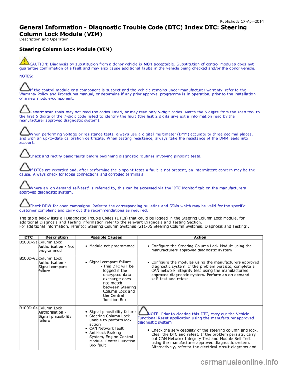
The table below lists all Diagnostic Trouble Codes (DTCs) that could be logged in the Steering Column Lock Module, for
additional Diagnosis and Testing information refer to the relevant Diagnosis and Testing Section.
For additional information, refer to: Steering Column Switches (211-05 Steering Column Switches, Diagnosis and Testing).
DTC Description Possible Causes Action B100D-51
Column Lock
Authorisation - Not
programmed
Module not programmed
Configure the Steering Column Lock Module using the
manufacturers approved diagnostic system B100D-62
Column Lock
Authorisation -
Signal compare
failure
Signal compare failure
- This DTC will be
logged if the
encrypted data
exchange does
not match
between Steering
Column Lock and
the Central
Junction Box
Configure the modules using the manufacturers approved
diagnostic system. If the problem persists, complete a
CAN network integrity test using the manufacturers
approved diagnostic system. Perform an on demand
self-test and retest B100D-64
Column Lock
Authorisation -
Signal plausibility
failure
Signal plausibility failure
Steering Column Lock
unable to perform lock
action
CAN Network fault
Anti-lock Braking
System, Engine Control
Module, Central Junction
Box fault
NOTE: Prior to clearing this DTC, carry out the Vehicle
Functional Reset application using the manufacturer approved
diagnostic system
Check the serviceability of the steering column and lock.
Clear the DTC and retest. If the problem persists, carry
out CAN Network Integrity Test and Module Self Test
using the manufacturer approved diagnostic system.
Alternatively, refer to the electrical circuit diagrams and
Page 243 of 3039
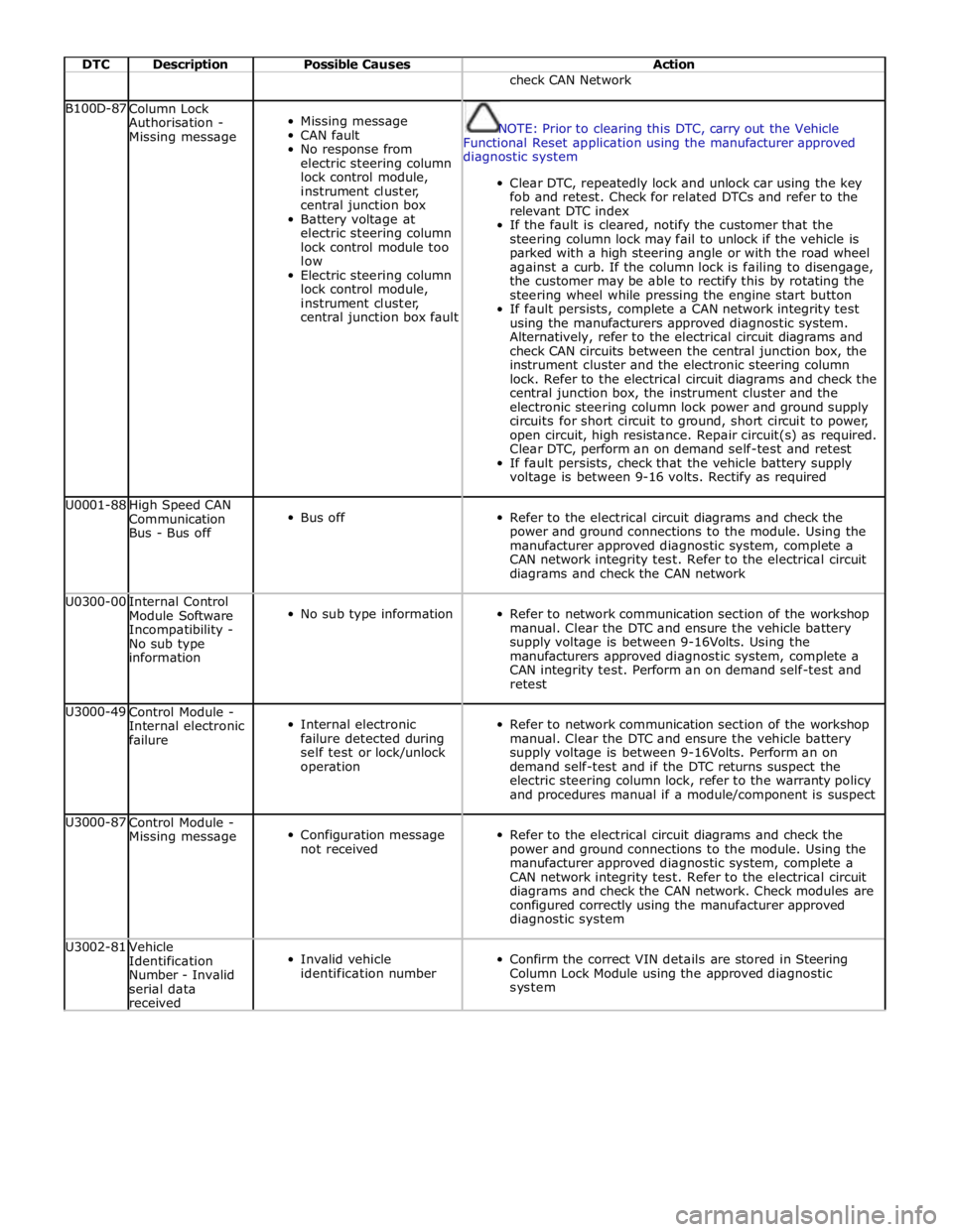
DTC Description Possible Causes Action check CAN Network B100D-87
Column Lock
Authorisation -
Missing message
Missing message
CAN fault
No response from
electric steering column
lock control module,
instrument cluster,
central junction box
Battery voltage at
electric steering column
lock control module too
low
Electric steering column
lock control module,
instrument cluster,
central junction box fault
NOTE: Prior to clearing this DTC, carry out the Vehicle
Functional Reset application using the manufacturer approved
diagnostic system
Clear DTC, repeatedly lock and unlock car using the key
fob and retest. Check for related DTCs and refer to the
relevant DTC index
If the fault is cleared, notify the customer that the
steering column lock may fail to unlock if the vehicle is
parked with a high steering angle or with the road wheel
against a curb. If the column lock is failing to disengage,
the customer may be able to rectify this by rotating the
steering wheel while pressing the engine start button
If fault persists, complete a CAN network integrity test
using the manufacturers approved diagnostic system.
Alternatively, refer to the electrical circuit diagrams and
check CAN circuits between the central junction box, the
instrument cluster and the electronic steering column
lock. Refer to the electrical circuit diagrams and check the
central junction box, the instrument cluster and the
electronic steering column lock power and ground supply
circuits for short circuit to ground, short circuit to power,
open circuit, high resistance. Repair circuit(s) as required.
Clear DTC, perform an on demand self-test and retest
If fault persists, check that the vehicle battery supply
voltage is between 9-16 volts. Rectify as required U0001-88
High Speed CAN
Communication
Bus - Bus off
Bus off
Refer to the electrical circuit diagrams and check the
power and ground connections to the module. Using the
manufacturer approved diagnostic system, complete a
CAN network integrity test. Refer to the electrical circuit
diagrams and check the CAN network U0300-00
Internal Control
Module Software
Incompatibility -
No sub type
information
No sub type information
Refer to network communication section of the workshop
manual. Clear the DTC and ensure the vehicle battery
supply voltage is between 9-16Volts. Using the
manufacturers approved diagnostic system, complete a
CAN integrity test. Perform an on demand self-test and
retest U3000-49
Control Module -
Internal electronic
failure
Internal electronic
failure detected during
self test or lock/unlock
operation
Refer to network communication section of the workshop
manual. Clear the DTC and ensure the vehicle battery
supply voltage is between 9-16Volts. Perform an on
demand self-test and if the DTC returns suspect the
electric steering column lock, refer to the warranty policy
and procedures manual if a module/component is suspect U3000-87
Control Module -
Missing message
Configuration message
not received
Refer to the electrical circuit diagrams and check the
power and ground connections to the module. Using the
manufacturer approved diagnostic system, complete a
CAN network integrity test. Refer to the electrical circuit
diagrams and check the CAN network. Check modules are
configured correctly using the manufacturer approved
diagnostic system U3002-81
Vehicle
Identification
Number - Invalid
serial data
received
Invalid vehicle
identification number
Confirm the correct VIN details are stored in Steering
Column Lock Module using the approved diagnostic
system
Page 260 of 3039

DTC Description Possible Causes Action suspect. P0783-77
3-4 Shift - Commanded
position not reachable
Gear Ratio Monitoring.
Mechanical Failures
Check and correct oil level. Clear DTC. If code
re-detects suspect Transmission (mechanical)
internal fault. Install a new Transmission as
required, refer to the warranty policy and
procedures manual if a module/component is
suspect. P0784-07
4-5 Shift - Mechanical
Failures
Gear Ratio Monitoring.
Mechanical Failures
Check and correct oil level. Clear DTC. If code
re-detects suspect Transmission (mechanical)
internal fault. Install a new Transmission as
required, refer to the warranty policy and
procedures manual if a module/component is
suspect. P0784-77
4-5 Shift - Commanded
position not reachable
Gear Ratio Monitoring.
Mechanical Failures
Check and correct oil level. Clear DTC. If code
re-detects suspect Transmission (mechanical)
internal fault. Install a new Transmission as
required, refer to the warranty policy and
procedures manual if a module/component is
suspect. P0798-1A
Pressure Control Solenoid
C Electrical - Circuit
Resistance Below Threshold
Pressure control solenoid
C Circuit resistance below
threshold
Suspect the Transmission Control Module. Install a
new Transmission Control Module as required,
refer to the warranty policy and procedures manual
if a module/component is suspect. P0798-1E
Pressure Control Solenoid
C Electrical - Circuit Short
to Ground
Pressure control solenoid
C electrical circuit short
to ground
Suspect the Transmission Control Module. Install a
new Transmission Control Module as required,
refer to the warranty policy and procedures manual
if a module/component is suspect. P0798-21
Pressure Control Solenoid
C Electrical - Signal
amplitude < minimum
Pressure Control Solenoid
C Electrical signal
amplitude < minimum
Suspect the Transmission Control Module. Install a
new Transmission Control Module as required,
refer to the warranty policy and procedures manual
if a module/component is suspect. P0814-62 Transmission Range
Display Circuit - Signal
compare failure
Transmission Range
Display Circuit signal
compare failure
Suspect the Transmission Control Module. Install a
new Transmission Control Module as required,
refer to the warranty policy and procedures manual
if a module/component is suspect. P0826-08
Up and Down Switch
circuit - Bus Signal
Message Failures
Invalid CAN signal from
Central Junction
Box/Instrument Cluster
Stuck Sprintronic switch
CAN bus circuit fault
Check Central Junction Box and Instrument Cluster
for stored DTCs. Check gear change switches for
correct operation. Refer to circuit diagrams and
check CAN bus for a circuit fault P0826-81
Up and Down Switch
Circuit - Invalid serial
data received
Invalid Can signal from
Central Junction Box /
Instrument Cluster
Stuck Sprintronic switch
CAN Bus Circuit fault
Check Central Junction Box and Instrument Cluster
for stored DTCs. Check Gear Change Switches for
correct operation. Refer to Circuit diagrams and
check CAN Bus for Circuit fault P0826-88
Up and Down Switch
Circuit - Bus off
Steering Wheel Module to
Central Junction Box /
Instrument Cluster LIN
Bus failure
Check Central Junction Box and Steering Wheel
Ice Switches for stored DTCs. Refer to Circuit
diagrams and check LIN Bus for Circuit fault P0829-07
5-6 Shift - Mechanical
Failures
Gear Ratio Monitoring.
Mechanical Failures
Check and correct oil level. Clear DTC. If code
re-detects suspect Transmission (mechanical)
internal fault. Install a new Transmission as
required, refer to the warranty policy and
procedures manual if a module/component is
suspect. www.JagDocs.com
Page 267 of 3039

DTC Description Possible Causes Action U0100-82
Lost Communication With
ECM/PCM "A" - Alive /
sequence counter
incorrect / not updated
Alive counter fault
Check Engine Control Module for stored DTCs U0100-83
Lost Communication With
ECM/PCM "A" - Value of
signal protection
calculation incorrect
Checksum fault
Check Engine Control Module for stored DTCs U0100-87
Lost Communication With
ECM/PCM "A" - Missing
message
CAN Timeout
NOTE: Do NOT install a new Engine Control Module
if an Engine Control Module Timeout DTC is only logged in
the Transmission Control Module, the failure is NOT with
the Engine Control Module
Check Engine Control Module for stored DTCs.
Check CAN Bus Circuit for fault U0103-82
Lost Communication With
Gear Shift Control Module
A - Alive / sequence
counter incorrect / not updated
Alive counter fault
Check Transmission Shift Module for stored DTCs.
Check CAN Bus Circuit for fault U0103-83
Lost Communication With
Gear Shift Control Module
A - Value of signal
protection calculation
incorrect
Checksum fault
Check Transmission Shift Module for stored DTCs.
Check CAN Bus Circuit for fault U0103-87
Lost Communication With
Gear Shift Control Module
A - Missing message
CAN Timeout
Check Transmission Shift Module for stored DTCs.
Check CAN Bus Circuit for fault U0122-82
Lost Communication With
Vehicle Dynamics Control
Module - Alive /
sequence counter
incorrect / not updated
Alive counter fault
Check Dynamic Stability Control (ABS) for stored
DTCs. Check CAN Bus Circuit for fault U0122-83
Lost Communication With
Vehicle Dynamics Control
Module - Value of signal
protection calculation
incorrect
Checksum fault
Check Dynamic Stability Control (ABS) for stored
DTCs. Check CAN Bus Circuit for fault U0122-87
Lost Communication With
Vehicle Dynamics Control
Module - Missing message
CAN Timeout
Check Dynamic Stability Control (ABS) for stored
DTCs. Check CAN Bus Circuit for fault U0126-00
Lost Communication With
Steering Angle Sensor
Module - No sub type
information
Lost Communication With
Steering Angle Sensor
Module
Check SAS for stored DTCs. Check CAN Bus Circuit
for fault U0128-87
Lost Communication With
Park Brake Control
Module - Missing message
CAN timeout electronic
parking brake module
Check Electronic Parking Brake Module (EPB) for
stored DTCs. Check CAN Bus Circuit for fault U0140-82
Lost Communication With
Body Control Module -
Alive / sequence counter
incorrect / not updated
Alive counter fault
Check Central Junction Box for stored DTCs. Check
CAN Bus Circuit for fault U0140-83
Lost Communication With
Body Control Module -
Value of signal protection
calculation incorrect
Checksum fault
Check Central Junction Box for stored DTCs. Check
CAN Bus Circuit for fault U0140-87
Lost Communication With
Body Control Module -
Missing message
CAN Timeout
Check Central Junction Box for stored DTCs. Check
CAN Bus Circuit for fault U0155-87
Lost Communication With
Instrument Panel Cluster
(IPC) Control Module - Missing message
CAN timeout instrument
cluster
Check Instrument Cluster for stored DTCs. Check
CAN Bus Circuit for fault U0300-68
Control Module - Event
information
Transmission software
does not match vehicle
network
Check Central Junction Box software level, Check
Transmission Control Module Software level,
Update software as required using the
manufacturer approved process
Page 282 of 3039
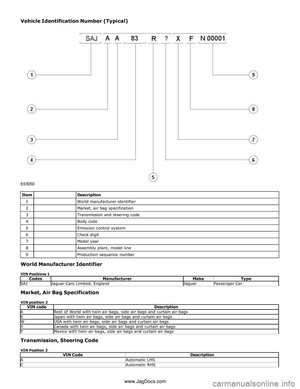
1
World manufacturer identifier 2
Market, air bag specification 3
Transmission and steering code 4
Body code 5
Emission control system 6
Check digit 7
Model year 8
Assembly plant, model line 9
Production sequence number World Manufacturer Identifier
VIN Positions 1
Codes Manufacturer Make Type SAJ Jaguar Cars Limited, England Jaguar Passenger Car Market, Air Bag Specification
VIN position 2
VIN code Description A Rest of World with twin air bags, side air bags and curtain air bags K Japan with twin air bags, side air bags and curtain air bags W USA with twin air bags, side air bags and curtain air bags X Canada with twin air bags, side air bags and curtain air bags Y Mexico with twin air bags, side air bags and curtain air bags Transmission, Steering Code
VIN Position 3
VIN Code Description A Automatic LHS C Automatic RHS www.JagDocs.com
Page 295 of 3039
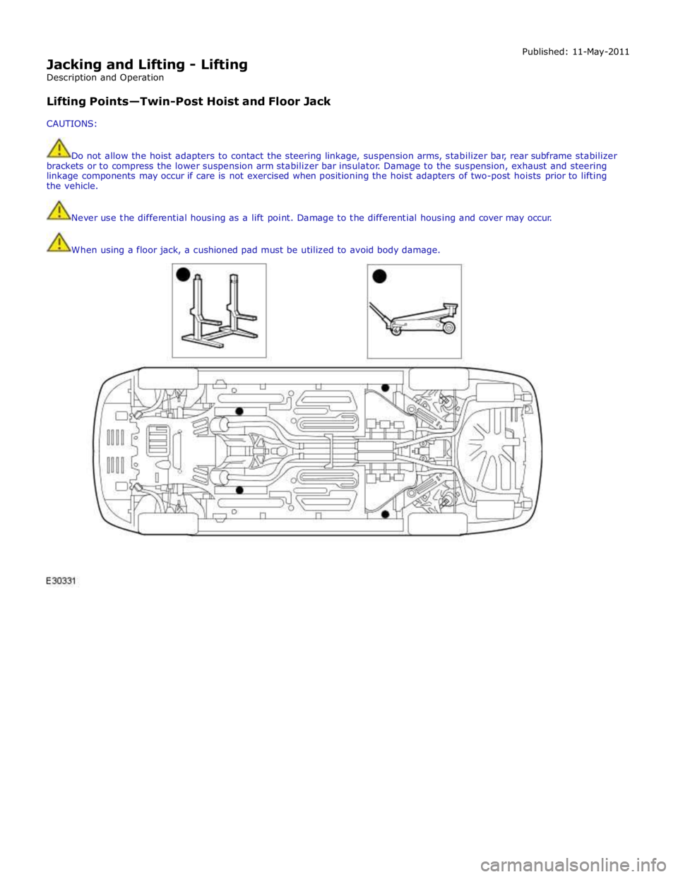
Jacking and Lifting - Lifting
Description and Operation
Lifting Points—Twin-Post Hoist and Floor Jack
CAUTIONS: Published: 11-May-2011
Do not allow the hoist adapters to contact the steering linkage, suspension arms, stabilizer bar, rear subframe stabilizer
brackets or to compress the lower suspension arm stabilizer bar insulator. Damage to the suspension, exhaust and steering
linkage components may occur if care is not exercised when positioning the hoist adapters of two-post hoists prior to lifting
the vehicle.
Never use the differential housing as a lift point. Damage to the differential housing and cover may occur.
When using a floor jack, a cushioned pad must be utilized to avoid body damage.
Page 297 of 3039
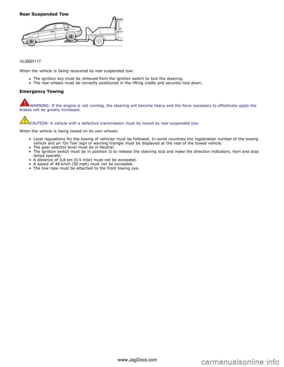
Rear Suspended Tow
When the vehicle is being recovered by rear suspended tow:
The ignition key must be removed from the ignition switch to lock the steering.
The rear wheels must be correctly positioned in the lifting cradle and securely tied down.
Emergency Towing
WARNING: If the engine is not running, the steering will become heavy and the force necessary to effectively apply the
brakes will be greatly increased.
CAUTION: A vehicle with a defective transmission must be towed by rear suspended tow.
When the vehicle is being towed on its own wheels:
Local regulations for the towing of vehicles must be followed. In some countries the registration number of the towing
vehicle and an 'On Tow' sign or warning triangle must be displayed at the rear of the towed vehicle.
The gear selector lever must be in Neutral.
The ignition switch must be in position II to release the steering lock and make the direction indicators, horn and stop
lamps operate.
A distance of 0,8 km (0.5 mile) must not be exceeded.
A speed of 48 km/h (30 mph) must not be exceeded.
The tow rope must be attached to the front towing eye. www.JagDocs.com