ESP inoperative JAGUAR XFR 2010 1.G Workshop Manual
[x] Cancel search | Manufacturer: JAGUAR, Model Year: 2010, Model line: XFR, Model: JAGUAR XFR 2010 1.GPages: 3039, PDF Size: 58.49 MB
Page 1349 of 3039

Published: 03-Jun-2014
Evaporative Emissions - V8 5.0L Petrol/V8 S/C 5.0L Petrol - Evaporative
Emissions
Diagnosis and Testing
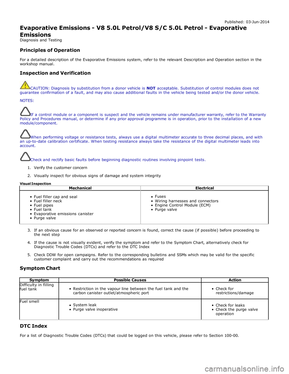
Principles of Operation
For a detailed description of the Evaporative Emissions system, refer to the relevant Description and Operation section in the
workshop manual.
Inspection and Verification
CAUTION: Diagnosis by substitution from a donor vehicle is NOT acceptable. Substitution of control modules does not
guarantee confirmation of a fault, and may also cause additional faults in the vehicle being tested and/or the donor vehicle.
NOTES:
If a control module or a component is suspect and the vehicle remains under manufacturer warranty, refer to the Warranty
Policy and Procedures manual, or determine if any prior approval programme is in operation, prior to the installation of a new
module/component.
When performing voltage or resistance tests, always use a digital multimeter accurate to three decimal places, and with
an up-to-date calibration certificate. When testing resistance always take the resistance of the digital multimeter leads into
account.
Check and rectify basic faults before beginning diagnostic routines involving pinpoint tests.
1. Verify the customer concern
2. Visually inspect for obvious signs of damage and system integrity
Visual Inspection
Mechanical Electrical
Fuel filler cap and seal
Fuel filler neck
Fuel pipes
Fuel tank
Evaporative emissions canister
Purge valve
Fuses
Wiring harnesses and connectors
Engine Control Module (ECM)
Purge valve
3. If an obvious cause for an observed or reported concern is found, correct the cause (if possible) before proceeding to
the next step
4. If the cause is not visually evident, verify the symptom and refer to the Symptom Chart, alternatively check for
Diagnostic Trouble Codes (DTCs) and refer to the DTC Index
5. Check DDW for open campaigns. Refer to the corresponding bulletins and SSMs which may be valid for the specific
customer complaint and carry out the recommendations as required
Symptom Chart
Symptom Possible Causes Action Difficulty in filling
fuel tank
Restriction in the vapour line between the fuel tank and the
carbon canister outlet/atmospheric port
Check for
restrictions/damage Fuel smell
System leak
Purge valve inoperative
Check for leaks
Check the purge valve
operation DTC Index
For a list of Diagnostic Trouble Codes (DTCs) that could be logged on this vehicle, please refer to Section 100-00.
Page 1793 of 3039

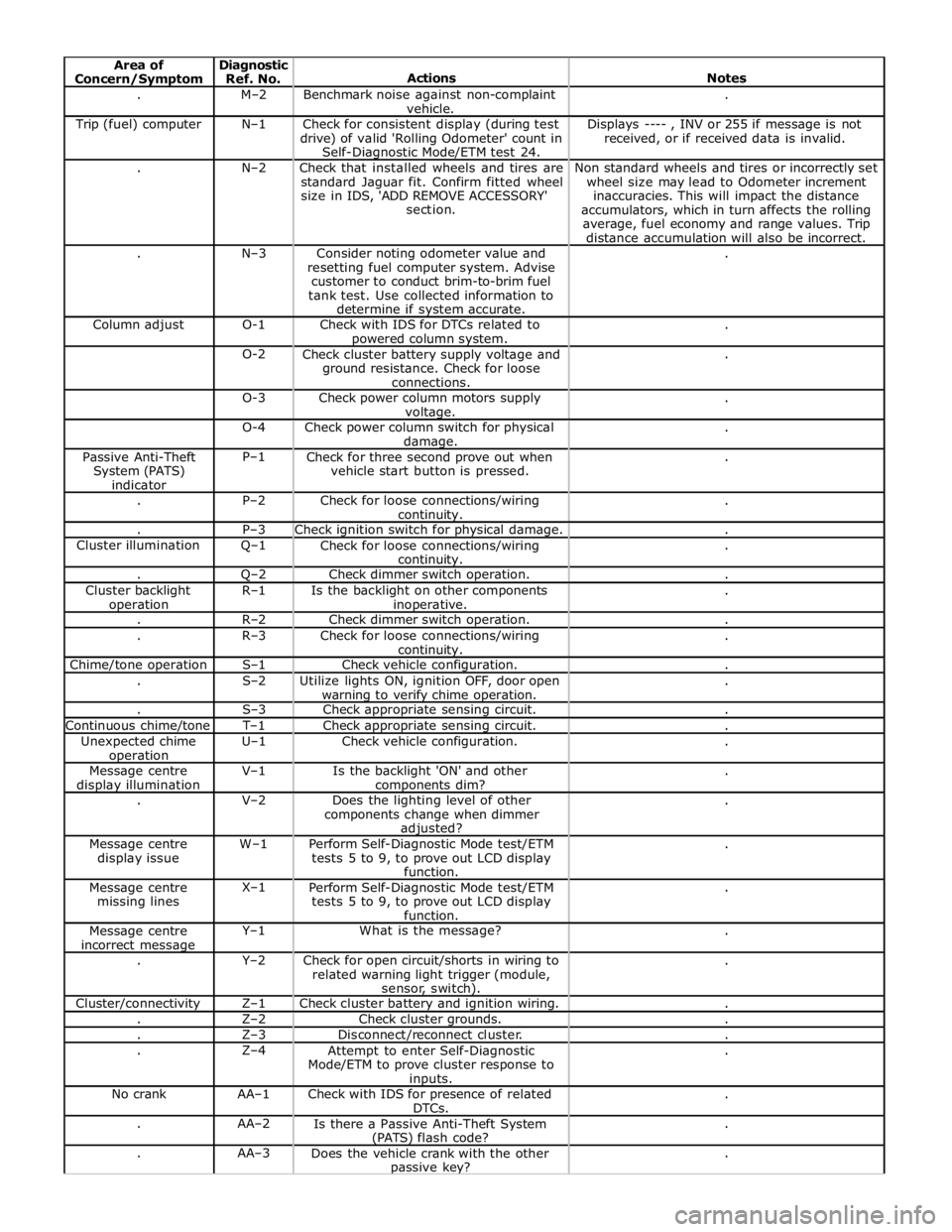
. M–2
Benchmark noise against non-complaint
vehicle. . Trip (fuel) computer N–1
Check for consistent display (during test
drive) of valid 'Rolling Odometer' count in
Self-Diagnostic Mode/ETM test 24. Displays ---- , INV or 255 if message is not
received, or if received data is invalid. . N–2
Check that installed wheels and tires are
standard Jaguar fit. Confirm fitted wheel
size in IDS, 'ADD REMOVE ACCESSORY'
section. Non standard wheels and tires or incorrectly set
wheel size may lead to Odometer increment
inaccuracies. This will impact the distance
accumulators, which in turn affects the rolling
average, fuel economy and range values. Trip
distance accumulation will also be incorrect. . N–3
Consider noting odometer value and
resetting fuel computer system. Advise
customer to conduct brim-to-brim fuel
tank test. Use collected information to
determine if system accurate. . Column adjust O-1
Check with IDS for DTCs related to powered column system. . O-2
Check cluster battery supply voltage and
ground resistance. Check for loose
connections. . O-3
Check power column motors supply voltage. . O-4
Check power column switch for physical damage. . Passive Anti-Theft
System (PATS)
indicator P–1
Check for three second prove out when
vehicle start button is pressed. . . P–2
Check for loose connections/wiring continuity. . . P–3 Check ignition switch for physical damage. . Cluster illumination Q–1
Check for loose connections/wiring continuity. . . Q–2 Check dimmer switch operation. . Cluster backlight operation R–1
Is the backlight on other components inoperative. . . R–2 Check dimmer switch operation. . . R–3
Check for loose connections/wiring continuity. . Chime/tone operation S–1 Check vehicle configuration. . . S–2
Utilize lights ON, ignition OFF, door open warning to verify chime operation. . . S–3 Check appropriate sensing circuit. . Continuous chime/tone T–1 Check appropriate sensing circuit. . Unexpected chime operation U–1 Check vehicle configuration. . Message centre display illumination V–1
Is the backlight 'ON' and other components dim? . . V–2
Does the lighting level of other
components change when dimmer adjusted? . Message centre
display issue W–1
Perform Self-Diagnostic Mode test/ETM
tests 5 to 9, to prove out LCD display
function. . Message centre
missing lines X–1
Perform Self-Diagnostic Mode test/ETM
tests 5 to 9, to prove out LCD display
function. . Message centre
incorrect message Y–1 What is the message? . . Y–2
Check for open circuit/shorts in wiring to
related warning light trigger (module,
sensor, switch). . Cluster/connectivity Z–1 Check cluster battery and ignition wiring. . . Z–2 Check cluster grounds. . . Z–3 Disconnect/reconnect cluster. . . Z–4
Attempt to enter Self-Diagnostic
Mode/ETM to prove cluster response to inputs. . No crank AA–1
Check with IDS for presence of related
DTCs. . . AA–2
Is there a Passive Anti-Theft System (PATS) flash code? . . AA–3
Does the vehicle crank with the other passive key? .
Page 2015 of 3039

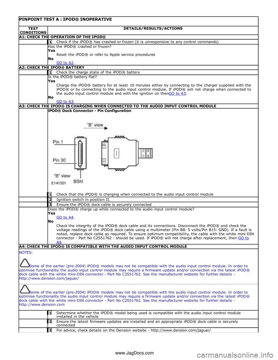
PINPOINT TEST A : IPOD® INOPERATIVE TEST
CONDITIONS DETAILS/RESULTS/ACTIONS A1: CHECK THE OPERATION OF THE IPOD® 1 Check if the iPOD® has crashed or frozen (it is unresponsive to any control commands) Has the iPOD® crashed or frozen?
Yes
Reset the iPOD® or refer to Apple service procedures
No
GO to A2. A2: CHECK THE IPOD® BATTERY 1 Check the charge state of the iPOD® battery Is the iPOD® battery flat?
Yes
Charge the iPOD® battery for at least 10 minutes either by connecting to the charger supplied with the
iPOD® or by connecting to the audio input control module. If iPOD® will not charge when connected to
the audio input control module and with the ignition on thenGO to A3. No
GO to A3. A3: CHECK THE IPOD® IS CHARGING WHEN CONNECTED TO THE AUDIO INPUT CONTROL MODULE iPOD® Dock Connector - Pin Configuration
1 Check that the iPOD® is charging when connected to the audio input control module 2 Ignition switch in position II. 3 Ensure the iPOD® dock cable is securely connected Does the iPOD® charge up while connected to the audio input control module?
Yes
GO to A4. No
Check the integrity of the iPOD® dock cable and its connections. Disconnect the iPOD® and check the
voltage readings of the iPOD® dock cable using a multimeter (Pin B8: 5 volts/Pin B15: GND). If a fault is
noted, replace dock cable as required. To ensure optimum compatibility, the cable with the white mini-DIN
connector - Part No C2S51762 - should be used. If iPOD® will not charge after replacement, then GO to A4. A4: CHECK THE IPOD® IS COMPATIBLE WITH THE AUDIO INPUT CONTROL MODULE NOTES:
Some of the earlier (pre-2004) iPOD® models may not be compatible with the audio input control module. In order to
optimise functionality the audio input control module may require a firmware update and/or connection via the latest iPOD®
dock cable with the white mini-DIN connector - Part No C2S51762. See the manufacturer website for further details -
http://www.dension.com/jaguar/
Some of the earlier (pre-2004) iPOD® models may not be compatible with the audio input control module. In order to
optimise functionality the audio input control module may require a firmware update and/or connection via the latest iPOD®
dock cable with the white mini-DIN connector - Part No C2S51762. See the manufacturer website for further details -
http://www.dension.com 1 Determine whether the iPOD® model being used is compatible with the audio input control module installed in the vehicle 2 Ensure the latest firmware updates are installed and an appropriate iPOD® dock cable is securely connected 3 For advice, check details on the Dension website - http://www.dension.com/jaguar/ www.JagDocs.com