change time JAGUAR XFR 2010 1.G Owner's Guide
[x] Cancel search | Manufacturer: JAGUAR, Model Year: 2010, Model line: XFR, Model: JAGUAR XFR 2010 1.GPages: 3039, PDF Size: 58.49 MB
Page 1883 of 3039
first charges the battery to its full condition.
NOTE: If the vehicle is only driven for short periods the charging process could take a number of days to complete.
Once the battery is fully charged, the BMS control module will discharge the battery to approximately 75% of its full state of
charge, but never lower than 12.2 V. The time taken to complete this part of the routine is dependent on the electrical load on
the vehicle.
When the second part of the routine has been successfully completed, the BMS control module will return the battery to its
optimum level of charge. The optimum level of charge will be between 12.6 V and 15 V, depending on battery condition,
temperature and loading.
The BMS control module also monitors the primary battery condition with the engine switched off. If a low voltage condition is
detected the BMS control module can request the infotainment system is switched off to protect battery voltage.
DUAL BATTERY SYSTEM - DUAL BATTERY SYSTEM VEHICLES ONLY
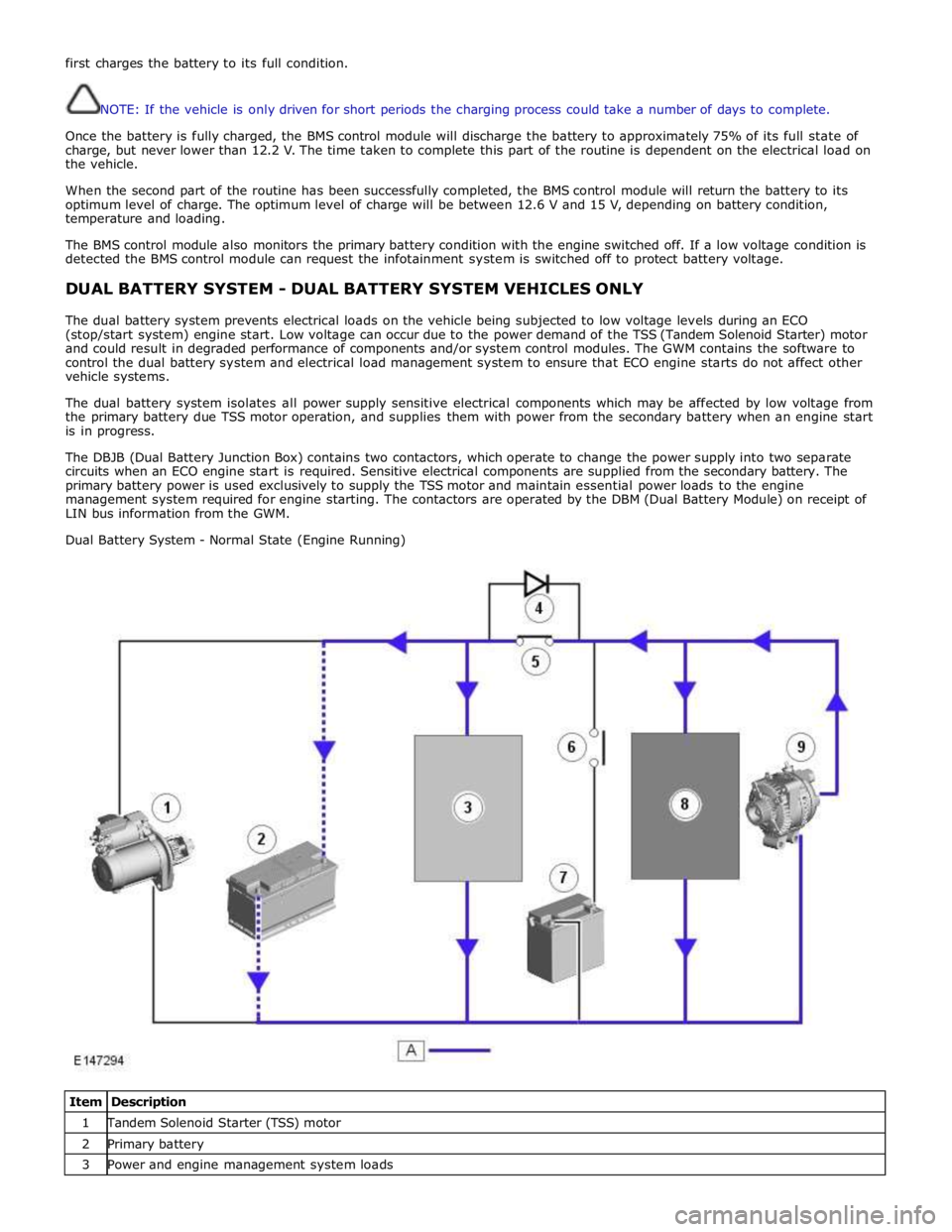
The dual battery system prevents electrical loads on the vehicle being subjected to low voltage levels during an ECO
(stop/start system) engine start. Low voltage can occur due to the power demand of the TSS (Tandem Solenoid Starter) motor
and could result in degraded performance of components and/or system control modules. The GWM contains the software to
control the dual battery system and electrical load management system to ensure that ECO engine starts do not affect other
vehicle systems.
The dual battery system isolates all power supply sensitive electrical components which may be affected by low voltage from
the primary battery due TSS motor operation, and supplies them with power from the secondary battery when an engine start
is in progress.
The DBJB (Dual Battery Junction Box) contains two contactors, which operate to change the power supply into two separate
circuits when an ECO engine start is required. Sensitive electrical components are supplied from the secondary battery. The
primary battery power is used exclusively to supply the TSS motor and maintain essential power loads to the engine
management system required for engine starting. The contactors are operated by the DBM (Dual Battery Module) on receipt of
LIN bus information from the GWM.
Dual Battery System - Normal State (Engine Running)
Item Description 1 Tandem Solenoid Starter (TSS) motor 2 Primary battery 3 Power and engine management system loads
Page 1886 of 3039
the secondary battery (if fitted) and passes through a grommet in the floorpan.
On new vehicles the primary battery positive terminal is fitted with a transit relay. The transit relay must removed using the
correct process detailed in the Pre Delivery Inspection (PDI) manual.
The battery negative terminal is fitted with a BMS control module. The control module is integral with the battery negative
cable and communicates with the GWM via a LIN bus connection. The battery condition information is passed to the GWM
which controls the generator output accordingly.
CAUTION: To avoid damage to the BMS control module, always use the body ground point in the engine compartment and
not the battery negative terminal when connecting a slave power supply.
Failure to use the recommended ground point will lead to the setting of a DTC. Incorrect information of battery condition will
be retained by the BMS control module due to the unmonitored current flow into the battery. The system will however,
recognize and compensate for the change in battery status after a period of time.
If a new battery is fitted, the BMS control module will require re-calibration using a Jaguar approved diagnostic system.
Replacement of the BMS control module requires no action as the control module will re-calibrate automatically.
SECONDARY BATTERY - DUAL BATTERY VEHICLES ONLY
The secondary battery is located in a tray on the next of the primary battery and is secured to the DBJB with a bracket. The
battery negative (-) terminal is connected via a cable to the vehicle body. The positive (+) terminal is connected by a cable to
the DBJB. The battery is vented via a tube which is connected with a T piece to the vent from the primary battery and passes
through a grommet in the floorpan.
The state of charge of the secondary battery is monitored by the Gateway Module (GWM).
BATTERY MONITORING SYSTEM (BMS)
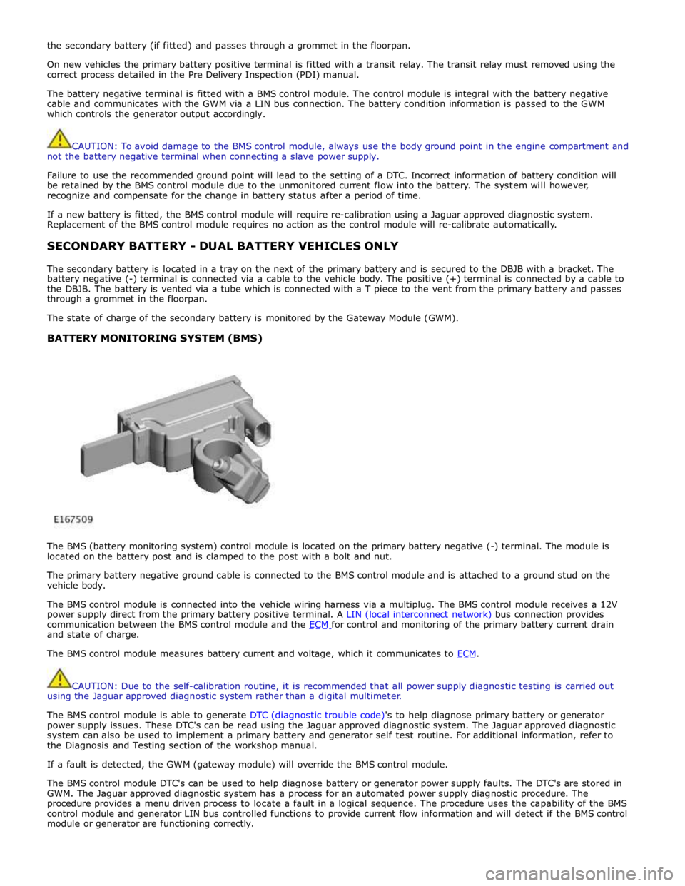
The BMS (battery monitoring system) control module is located on the primary battery negative (-) terminal. The module is
located on the battery post and is clamped to the post with a bolt and nut.
The primary battery negative ground cable is connected to the BMS control module and is attached to a ground stud on the
vehicle body.
The BMS control module is connected into the vehicle wiring harness via a multiplug. The BMS control module receives a 12V
power supply direct from the primary battery positive terminal. A LIN (local interconnect network) bus connection provides
communication between the BMS control module and the ECM for control and monitoring of the primary battery current drain and state of charge.
The BMS control module measures battery current and voltage, which it communicates to ECM.
CAUTION: Due to the self-calibration routine, it is recommended that all power supply diagnostic testing is carried out
using the Jaguar approved diagnostic system rather than a digital multimeter.
The BMS control module is able to generate DTC (diagnostic trouble code)'s to help diagnose primary battery or generator
power supply issues. These DTC's can be read using the Jaguar approved diagnostic system. The Jaguar approved diagnostic
system can also be used to implement a primary battery and generator self test routine. For additional information, refer to
the Diagnosis and Testing section of the workshop manual.
If a fault is detected, the GWM (gateway module) will override the BMS control module.
The BMS control module DTC's can be used to help diagnose battery or generator power supply faults. The DTC's are stored in
GWM. The Jaguar approved diagnostic system has a process for an automated power supply diagnostic procedure. The
procedure provides a menu driven process to locate a fault in a logical sequence. The procedure uses the capability of the BMS
control module and generator LIN bus controlled functions to provide current flow information and will detect if the BMS control
module or generator are functioning correctly.
Page 1899 of 3039
Battery
test
code,
must
be
given if
a
battery,
starter
motor
or
generator
is
exchanged
under
warranty
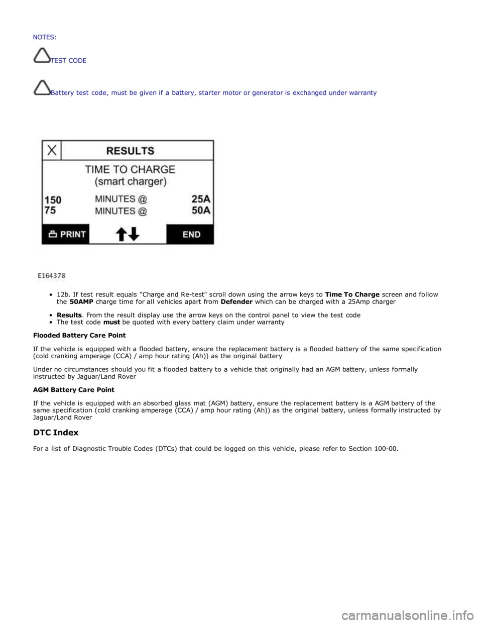
12b.
If
test
result
equals
"Charge
and
Re-test"
scroll
down
using
the
arrow
keys
to
Time To
Charge
screen and follow
the
50AMP
charge
time
for
all
vehicles
apart
from
Defender
which
can
be
charged
with a
25Amp
charger
Results.
From
the
result
display
use
the
arrow
keys
on
the
control
panel
to
view the
test
code
The
test
code
must
be
quoted
with every
battery
claim
under
warranty
Flooded
Battery
Care
Point
If
the
vehicle
is
equipped with
a
flooded
battery,
ensure
the
replacement
battery
is
a
flooded
battery
of
the
same
specification
(cold
cranking
amperage
(CCA)
/ amp
hour
rating
(Ah))
as
the
original
battery
Under
no
circumstances
should you
fit
a
flooded
battery
to a
vehicle
that
originally
had
an
AGM
battery,
unless
formally
instructed
by Jaguar/Land
Rover
AGM
Battery
Care
Point
If
the
vehicle
is
equipped with
an absorbed
glass
mat
(AGM)
battery,
ensure
the
replacement
battery
is
a
AGM
battery
of
the
same
specification
(cold
cranking
amperage
(CCA)
/
amp
hour
rating
(Ah))
as
the
original
battery,
unless
formally
instructed
by
Jaguar/Land
Rover
DTC
Index
For
a
list
of
Diagnostic
Trouble
Codes
(DTCs)
that
could
be
logged
on
this
vehicle,
please
refer
to
Section
100-00. NOTES:
TESTCODE
Page 1958 of 3039
The digital radio format adopted for NAS vehicles is satellite radio. Satellite service providers transmit a signal from their
up-link facility (which is the original point of transmission of data, voice or other information through an antenna system) to a
satellite where the signal is then down linked to both the terrestrial repeater network and the individual satellite car radios.
The radio switches between the satellite signal and the repeater network signal depending on the strength of the signal at any
given time.
The Sirius satellite system comprises:
Satellites
Ground repeaters
Up-link ground stations
Radio receiver systems
The Sirius satellite radio system uses three satellites on an inclined elliptical orbit. This ensures that each satellite spends
approximately 16 hours a day over the continent of the USA, with at least one satellite over the country at any one time.
The satellites beam their signals down to the ground where the signal is picked up by receivers or is transmitted to repeater
stations to cover built up areas where the signal is obscured. The satellite service comprises over 100 channels of digital
entertainment which is provided by subscription requiring a monthly payment.
Operation of the satellite radio system is the same as the radio operations with selections made through the Touch-screen and
ICP to access and navigate the system functions.
The satellite radio receiver is a dedicated tuner which is controlled by the ICM on the MOST ring. The receiver filters the
signals from the satellite radio antenna. Information is transmitted on the MOST ring and processed by the ICM. The processed
information is sent out to the power amplifier or IAM (with internal amplifier) and broadcast through the speaker system.
No configuration procedure is required if the satellite radio receiver is replaced. Calibration of the satellite radio receiver using
the Jaguar approved diagnostic equipment enables updates to be downloaded as new technology becomes available or any
fault concerns require software updates.
Satellite Radio Antenna
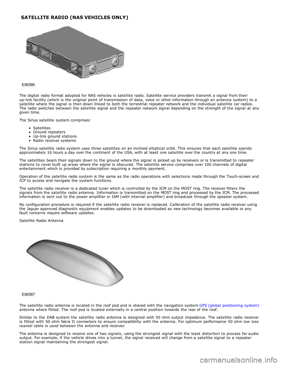
The satellite radio antenna is located in the roof pod and is shared with the navigation system GPS (global positioning system)
antenna where fitted. The roof pod is located externally in a central position towards the rear of the roof.
Similar to the DAB system the satellite radio antenna is designed with 50 ohm output impedance. The satellite radio receiver
is fitted with 50 ohm fakra II connectors to ensure compatibility with the antenna. For optimum performance 50 ohm low loss
coaxial cable is used between the antenna and receiver.
The antenna is designed to receive one of two signals, using the strongest signal with the least distortion to process for audio
output. For example, if the vehicle drives into a tunnel, the signal received will change from a satellite signal to a repeater
station signal maintaining the strongest signal. SATELLITE RADIO (NAS VEHICLES ONLY)
Page 1977 of 3039

In addition to the standard navigation system there are two market dependant systems that supply extra information to the
navigation system and the driver. These are:
TMC (traffic message channel) (Europe only)
VICS (vehicle information and communication system) (Japan only)
The TMC (traffic message channel) is a function of the FM (frequency modulation)RDS (radio data system). The system
broadcasts real-time traffic and weather information. Data messages are received and decoded by the TMC (traffic message
channel) integral receiver and processed by the navigation computer. TMC (traffic message channel) messages can be filtered
by the navigation computer so that only those relevant to the current journey are displayed, allowing the navigation system to
offer dynamic route guidance - alerting the driver of a problem on the planned route and calculating an alternative route to
avoid the incident. All TMC (traffic message channel) events on the map can be viewed not just the ones on the calculated
route.
TMC (traffic message channel) traffic information systems conform to a global standard that has been adopted by traffic data
gatherers, information service providers, broadcasters and vehicle/receiver manufacturers.
All TMC (traffic message channel) receivers use the same list of event codes, while the location database (on the map disc)
contains both a country-specific set of location codes for the strategic European road network.
TMC (traffic message channel) traffic data is currently broadcast in many European countries.
The VICS (vehicle information and communication system) is broadcast in the Japanese market.
The VICS (vehicle information and communication system) supplies information to enable the navigation computer to re-route
the navigation guidance or to inform the vehicle driver of traffic conditions in the vehicles vicinity. Information is provided to
the system through 3 routes:
RF (radio frequency) transmission
Infra-red transmission
FM multiplex transmissions
The RF (radio frequency) transmissions are generally transmitted from road side beacons mainly on expressways. The
information transmitted is as follows:
Traffic congestion
Travel time to next intersection
Traffic conditions in surrounding areas and expressway turn offs
Traffic accidents
Speed limits
Lane regulations
Tire change
Parking availability at expressway service areas and parking areas
Infra-Red transmissions are transmitted from road side beacons on major trunk roads. The information transmitted is:
Traffic congestion and travel time
Traffic accidents
Breakdowns
Road works restrictions
Parking availability
FM transmissions are broadcast as part of the FM multiplex broadcasting system from NHK FM stations. Information transmitted is:
Traffic congestion and travel time for wide areas
Traffic accidents, road works, speed limits and lane restrictions for a wide area
Parking availability information
The traffic data is split from the normal FM transmissions by the diversity antenna module.
Selection of 'Navigation' on the Touch-screen home menu and subsequent sub-menu selection sends a control request signal to
the navigation computer on the MOST (media orientated systems transport) ring. The requested control information is
processed by the navigation computer.
If voice guidance is operational the voice signal information is relayed from the navigation computer on the MOST (media
orientated systems transport) ring to either the IAM (integrated audio unit) or Power Amplifier, dependant on equipment level,
for output on the speaker system. The navigation audio output is through the front speakers whilst the background audio, for
example radio or CD (compact disc), is played at a reduced volume on the rear speakers.
The GPS signal is available to the navigation system at all times when the vehicle ignition is switched on.
Navigation user voice commands are made using the JaguarVoice system. The ICM (information control module) processes the
analogue signal from the JaguarVoice switch into a digital signal. The digital signal is passed from the ICM (information control
module) onto the MOST (media orientated systems transport) system to the JaguarVoice control unit which is integral with the
navigation computer.
The navigation computer sends an instruction via the MOST (media orientated systems transport) ring to the IAM (integrated
audio module) to turn on the microphone facility.
The microphone is hardwired to the IAM (integrated audio module). The spoken voice command signals are relayed from the
IAM (integrated audio module) via the MOST (media orientated systems transport) ring to the navigation computer for
Page 2013 of 3039
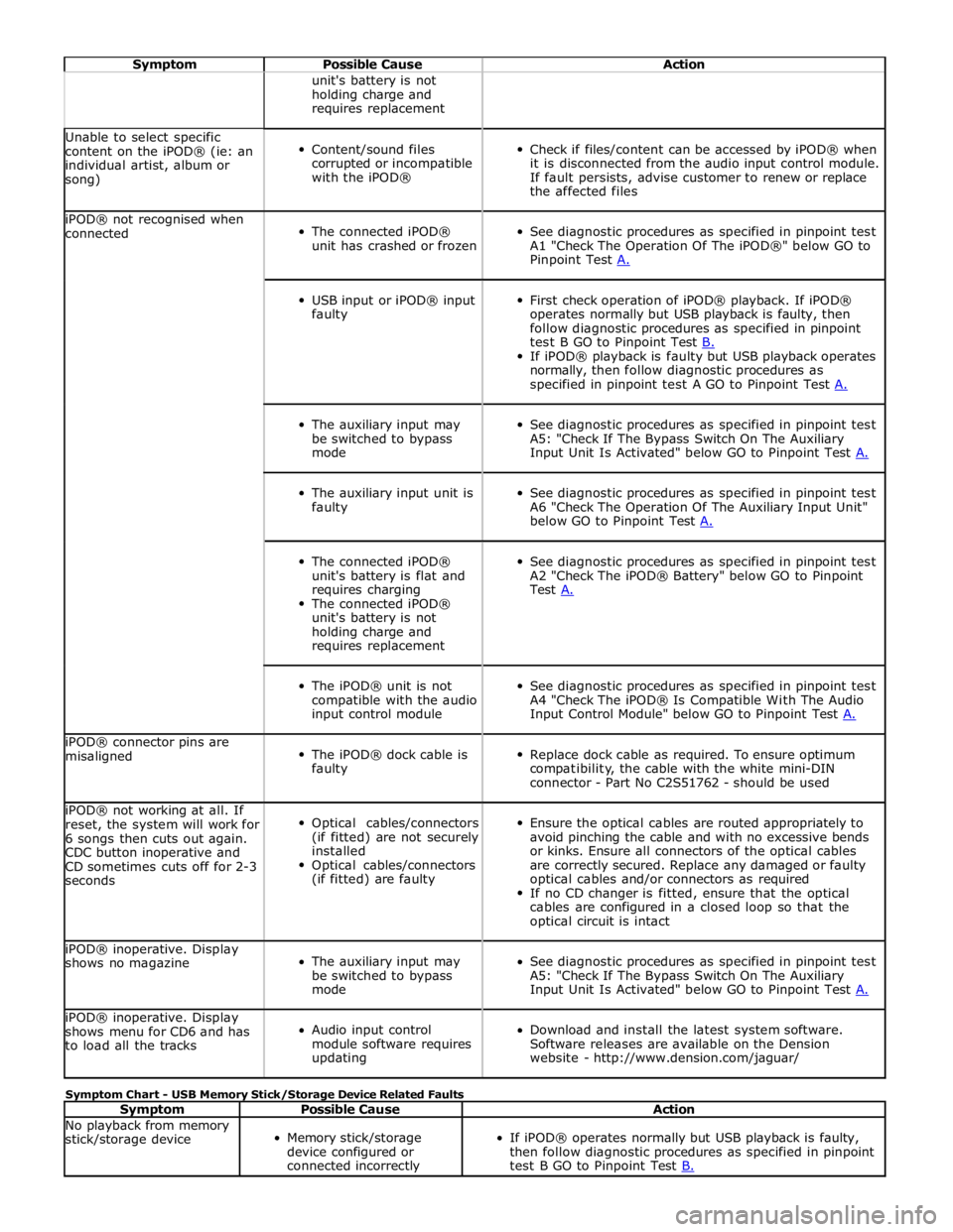
Symptom Possible Cause Action unit's battery is not
holding charge and
requires replacement Unable to select specific
content on the iPOD® (ie: an
individual artist, album or
song)
Content/sound files
corrupted or incompatible
with the iPOD®
Check if files/content can be accessed by iPOD® when
it is disconnected from the audio input control module.
If fault persists, advise customer to renew or replace
the affected files iPOD® not recognised when
connected
The connected iPOD®
unit has crashed or frozen
See diagnostic procedures as specified in pinpoint test
A1 "Check The Operation Of The iPOD®" below GO to
Pinpoint Test A.
USB input or iPOD® input
faulty
First check operation of iPOD® playback. If iPOD®
operates normally but USB playback is faulty, then
follow diagnostic procedures as specified in pinpoint
test B GO to Pinpoint Test B. If iPOD® playback is faulty but USB playback operates
normally, then follow diagnostic procedures as
specified in pinpoint test A GO to Pinpoint Test A.
The auxiliary input may
be switched to bypass
mode
See diagnostic procedures as specified in pinpoint test
A5: "Check If The Bypass Switch On The Auxiliary
Input Unit Is Activated" below GO to Pinpoint Test A.
The auxiliary input unit is
faulty
See diagnostic procedures as specified in pinpoint test
A6 "Check The Operation Of The Auxiliary Input Unit"
below GO to Pinpoint Test A.
The connected iPOD®
unit's battery is flat and
requires charging
The connected iPOD®
unit's battery is not
holding charge and
requires replacement
See diagnostic procedures as specified in pinpoint test
A2 "Check The iPOD® Battery" below GO to Pinpoint
Test A.
The iPOD® unit is not
compatible with the audio
input control module
See diagnostic procedures as specified in pinpoint test
A4 "Check The iPOD® Is Compatible With The Audio
Input Control Module" below GO to Pinpoint Test A. iPOD® connector pins are
misaligned
The iPOD® dock cable is
faulty
Replace dock cable as required. To ensure optimum
compatibility, the cable with the white mini-DIN
connector - Part No C2S51762 - should be used iPOD® not working at all. If
reset, the system will work for
6 songs then cuts out again.
CDC button inoperative and
CD sometimes cuts off for 2-3
seconds
Optical cables/connectors
(if fitted) are not securely
installed
Optical cables/connectors
(if fitted) are faulty
Ensure the optical cables are routed appropriately to
avoid pinching the cable and with no excessive bends
or kinks. Ensure all connectors of the optical cables
are correctly secured. Replace any damaged or faulty
optical cables and/or connectors as required
If no CD changer is fitted, ensure that the optical
cables are configured in a closed loop so that the
optical circuit is intact iPOD® inoperative. Display
shows no magazine
The auxiliary input may
be switched to bypass
mode
See diagnostic procedures as specified in pinpoint test
A5: "Check If The Bypass Switch On The Auxiliary
Input Unit Is Activated" below GO to Pinpoint Test A. iPOD® inoperative. Display
shows menu for CD6 and has
to load all the tracks
Audio input control
module software requires
updating
Download and install the latest system software.
Software releases are available on the Dension
website - http://www.dension.com/jaguar/ Symptom Chart - USB Memory Stick/Storage Device Related Faults
Symptom Possible Cause Action No playback from memory
stick/storage device
Memory stick/storage
device configured or
connected incorrectly
If iPOD® operates normally but USB playback is faulty,
then follow diagnostic procedures as specified in pinpoint
test B GO to Pinpoint Test B.
Page 2027 of 3039
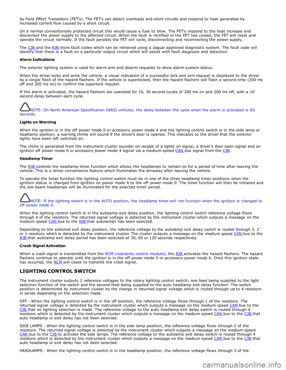
by Field Effect Transistors (FET's). The FET's can detect overloads and short circuits and respond to heat generated by
increased current flow caused by a short circuit.
On a normal conventionally protected circuit this would cause a fuse to blow. The FET's respond to the heat increase and
disconnect the power supply to the affected circuit. When the fault is rectified or the FET has cooled, the FET will reset and
operate the circuit normally. If the fault persists the FET will cycle, disconnecting and reconnecting the power supply.
The CJB and the RJB store fault codes which can be retrieved using a Jaguar approved diagnostic system. The fault code will identify that there is a fault on a particular output circuit which will assist with fault diagnosis and detection.
Alarm Indications
The exterior lighting system is used for alarm arm and disarm requests to show alarm system status.
When the driver locks and arms the vehicle, a visual indication of a successful lock and arm request is displayed to the driver
by a single flash of the hazard flashers. If the vehicle is superlocked, then the hazard flashers will flash a second time (200 ms
off and 200 ms on) to confirm the superlock request.
If the alarm is activated, the hazard flashers are operated for 10, 30 second cycles of 200 ms on and 200 ms off, with a 10
second delay between each cycle.
NOTE: On North American Specification (NAS) vehicles, the delay between the cycle when the alarm is activated is 60
seconds.
Lights on Warning
When the ignition is in the off power mode 0 or accessory power mode 4 and the lighting control switch is in the side lamp or
headlamp position, a warning chime will sound if the driver's door is opened. This indicates to the driver that the exterior
lights have been left switched on.
The chime is generated from the instrument cluster sounder on receipt of a lights on signal, a driver's door open signal and an
ignition off power mode 0 or accessory power mode 4 signal via a medium speed CAN bus signal from the CJB. Headlamp Timer
The RJB controls the headlamp timer function which allows the headlamps to remain on for a period of time after leaving the vehicle. This is a driver convenience feature which illuminates the driveway after leaving the vehicle.
To operate the timer function the lighting control switch must be in one of the three headlamp timer positions when the
ignition status is changed from ignition on power mode 6 to the off power mode 0. The timer function will then be initiated and
the low beam headlamps will be illuminated for the selected timer period.
NOTE: If the lighting switch is in the AUTO position, the headlamp timer will not function when the ignition is changed to
off power mode 0.
When the lighting control switch is in the autolamp exit delay position, the lighting control switch reference voltage flows
through 4 of the resistors. The returned signal voltage is detected by the instrument cluster which outputs a message on the
medium speed CAN bus to the RJB that autolamps has been selected.
Depending on the selected exit delay position, the reference voltage to the autolamp exit delay switch is routed through 3, 2
or 1 resistors which is detected by the instrument cluster. The cluster outputs a message on the medium speed CAN bus to the RJB that autolamp exit delay period has been selected at 30, 60 or 120 seconds respectively. Crash Signal Activation
When a crash signal is transmitted from the RCM (restraints control module), the RJB activates the hazard flashers. The hazard flashers continue to operate until the ignition is in the off power mode 0 or accessory power mode 6. Once this ignition state
has occurred, the RCM will cease to transmit the crash signal.
LIGHTING CONTROL SWITCH
The instrument cluster outputs 2 reference voltages to the rotary lighting control switch; one feed being supplied to the light
selection function of the switch and the second feed being supplied to the auto headlamp exit delay function. The switch
position is determined by instrument cluster by the change in returned signal voltage which is routed through up to 4 resistors
in series depending on the selection made.
OFF - When the lighting control switch is in the off position, the reference voltage flows through 1 of the resistors. The
returned signal voltage is detected by the instrument cluster which outputs a message on the medium speed CAN bus to the CJB that no lighting selection is made. The reference voltage to the auto headlamp exit delay switch is routed through 4 resistors which is detected by the instrument cluster which outputs a message on the medium speed CAN bus to the CJB that auto headlamp or exit delay has not been selected.
SIDE LAMPS - When the lighting control switch is in the side lamp position, the reference voltage flows through 2 of the
resistors. The returned signal voltage is detected by the instrument cluster which outputs a message on the medium speed
CAN bus to the CJB to activate the side lamps. The reference voltage to the autolamp exit delay switch is routed through 4 resistors which is detected by the instrument cluster which outputs a message on the medium speed CAN bus to the CJB that auto headlamp or exit delay has not been selected.
HEADLAMPS - When the lighting control switch is in the headlamp position, the reference voltage flows through 3 of the
Page 2028 of 3039
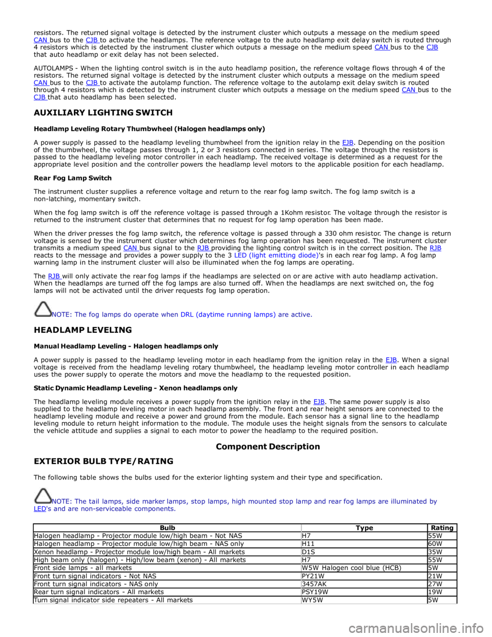
resistors. The returned signal voltage is detected by the instrument cluster which outputs a message on the medium speed
CAN bus to the CJB to activate the headlamps. The reference voltage to the auto headlamp exit delay switch is routed through 4 resistors which is detected by the instrument cluster which outputs a message on the medium speed CAN bus to the CJB that auto headlamp or exit delay has not been selected.
AUTOLAMPS - When the lighting control switch is in the auto headlamp position, the reference voltage flows through 4 of the
resistors. The returned signal voltage is detected by the instrument cluster which outputs a message on the medium speed
CAN bus to the CJB to activate the autolamp function. The reference voltage to the autolamp exit delay switch is routed through 4 resistors which is detected by the instrument cluster which outputs a message on the medium speed CAN bus to the CJB that auto headlamp has been selected.
AUXILIARY LIGHTING SWITCH
Headlamp Leveling Rotary Thumbwheel (Halogen headlamps only)
A power supply is passed to the headlamp leveling thumbwheel from the ignition relay in the EJB. Depending on the position of the thumbwheel, the voltage passes through 1, 2 or 3 resistors connected in series. The voltage through the resistors is
passed to the headlamp leveling motor controller in each headlamp. The received voltage is determined as a request for the
appropriate level position and the controller powers the headlamp level motors to the applicable position for each headlamp.
Rear Fog Lamp Switch
The instrument cluster supplies a reference voltage and return to the rear fog lamp switch. The fog lamp switch is a
non-latching, momentary switch.
When the fog lamp switch is off the reference voltage is passed through a 1Kohm resistor. The voltage through the resistor is
returned to the instrument cluster that determines that no request for fog lamp operation has been made.
When the driver presses the fog lamp switch, the reference voltage is passed through a 330 ohm resistor. The change is return
voltage is sensed by the instrument cluster which determines fog lamp operation has been requested. The instrument cluster
transmits a medium speed CAN bus signal to the RJB providing the lighting control switch is in the correct position. The RJB reacts to the message and provides a power supply to the 3 LED (light emitting diode)'s in each rear fog lamp. A fog lamp
warning lamp in the instrument cluster will also be illuminated when the fog lamps are operating.
The RJB will only activate the rear fog lamps if the headlamps are selected on or are active with auto headlamp activation. When the headlamps are turned off the fog lamps are also turned off. When the headlamps are next switched on, the fog
lamps will not be activated until the driver requests fog lamp operation.
NOTE: The fog lamps do operate when DRL (daytime running lamps) are active.
HEADLAMP LEVELING
Manual Headlamp Leveling - Halogen headlamps only
A power supply is passed to the headlamp leveling motor in each headlamp from the ignition relay in the EJB. When a signal voltage is received from the headlamp leveling rotary thumbwheel, the headlamp leveling motor controller in each headlamp
uses the power supply to operate the motors and move the headlamp to the requested position.
Static Dynamic Headlamp Leveling - Xenon headlamps only
The headlamp leveling module receives a power supply from the ignition relay in the EJB. The same power supply is also supplied to the headlamp leveling motor in each headlamp assembly. The front and rear height sensors are connected to the
headlamp leveling module and receive a power and ground from the module. Each sensor has a signal line to the headlamp
leveling module to return height information to the module. The module uses the height signals from the sensors to calculate
the vehicle attitude and supplies a signal to each motor to power the headlamp to the required position.
EXTERIOR BULB TYPE/RATING Component Description
The following table shows the bulbs used for the exterior lighting system and their type and specification.
NOTE: The tail lamps, side marker lamps, stop lamps, high mounted stop lamp and rear fog lamps are illuminated by
LED's and are non-serviceable components.
Bulb Type Rating Halogen headlamp - Projector module low/high beam - Not NAS H7 55W Halogen headlamp - Projector module low/high beam - NAS only H11 60W Xenon headlamp - Projector module low/high beam - All markets D1S 35W High beam only (halogen) - High/low beam (xenon) - All markets H7 55W Front side lamps - all markets W5W Halogen cool blue (HCB) 5W Front turn signal indicators - Not NAS PY21W 21W Front turn signal indicators - NAS only 3457AK 27W Rear turn signal indicators - All markets PSY19W 19W Turn signal indicator side repeaters - All markets WY5W 5W
Page 2029 of 3039
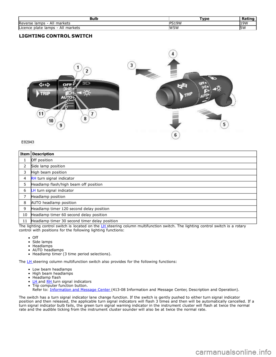
Bulb Type Rating Reverse lamps - All markets PS19W 19W Licence plate lamps - All markets W5W 5W LIGHTING CONTROL SWITCH
Item Description 1 Off position 2 Side lamp position 3 High beam position 4 RH turn signal indicator 5 Headlamp flash/high beam off position 6 LH turn signal indicator 7 Headlamp position 8 AUTO headlamp position 9 Headlamp timer 120 second delay position 10 Headlamp timer 60 second delay position 11 Headlamp timer 30 second timer delay position The lighting control switch is located on the LH steering column multifunction switch. The lighting control switch is a rotary control with positions for the following lighting functions:
Off
Side lamps
Headlamps
AUTO headlamps
Headlamp timer (3 time period selections).
The LH steering column multifunction switch also provides for the following functions: Low beam headlamps
High beam headlamps
Headlamp flash
LH and RH turn signal indicators Trip computer function button.
Refer to: Information and Message Center (413-08 Information and Message Center, Description and Operation).
The switch has a turn signal indicator lane change function. If the switch is gently pushed to either turn signal indicator
position and then released, the applicable turn signal indicators will flash 3 times and then will be automatically cancelled. If a
turn signal indicator bulb fails, the green turn signal warning indicator in the instrument cluster will flash at twice the normal
rate and the audible ticking from the instrument cluster sounder will also be at twice the normal rate.
Page 2032 of 3039
15 Xenon igniter unit and bulb 16 Xenon igniter electrical connector 17 Cornering/static bending lamp bulb (if fitted) 18 Side lamp bulb 19 High beam headlamp bulb 20 Cover - Side lamp, cornering/static bending lamp (if fitted) and high beam headlamp bulbs 21 Electrical connector Bi-Xenon Headlamp
The bi-xenon headlamp uses a projector lens, similar to the halogen headlamp. The projector module comprises an ellipsoidal
lens and a reflector. The projector reflector collects the light produced by the halogen bulb and projects the light into a focal
plane containing a shield. The contour of the shield is projected onto the road by the lens. A complex surface reflector is used
for the halogen fill in high beam lamp. This type of reflector is divided into separate parabolic segments, with each segment
having a different focal length. The low and high beam bulbs are quartz halogen H7, with a rating of 55W. The bulbs are
retained in the headlamp unit with conventional wire retaining clips.
A tourist lever mechanism is located on the right hand side of the projector module. This mechanism moves a flap to blank off
a portion of the beam spread to enable the vehicle to be driven in opposite drive hand markets without applying blanking
decals to the headlamp lens. The beam is changed by removing the access cover at the rear of the lamp assembly and moving
a small lever located near the bulb holder, at the side of the projector.
NOTE: The tourist lever is not fitted to NAS vehicles.
WARNING: The Xenon system generates up to 30000 volts and contact with this voltage could lead to fatality. Make sure
that the headlamps are switched off before working on the system.
The following safety precautions must be adhered to when working on the xenon low beam headlamp system:
DO NOT attempt any procedures on the xenon headlamps when the lights are switched on.
Handling of the D1S xenon bulb must be performed using suitable protective equipment; for example gloves and
goggles. The glass part of the bulb must not be touched.
Xenon bulbs must be disposed of as hazardous waste.
Only operate the bulb in a mounted condition in the projector module installed in the headlamp.
The xenon headlamp is known as 'bi-xenon' because it operates as both a low and high beam headlamp unit. The xenon lamp,
or High Intensity Discharge (HID) lamp as they are sometimes referred to, comprises an ellipsoidal lens with a solenoid
controlled shutter to change the beam output from low to high beam.
NOTE: If the lighting control switch is in the 'off' position, both the xenon lamp and the halogen high beam lamp will
operate when the high beam 'flash' function is operated.
The xenon headlamp system is controlled by the CJB using a control module for each headlamp and an igniter. The control modules and the igniters provide the regulated power supply required to illuminate the bulbs through their start-up phases of
operation.
The xenon headlamp is a self contained unit located within the headlamp assembly. The unit comprises a reflector, an adaptor
ring, the lens, a shutter controller and the xenon bulb, which together forms an assembly known as the projector module. The
reflector is curved and provides the mounting point for the xenon bulb. The bulb locates in a keyway to ensure the correct
alignment in the reflector and is secured by a plastic mounting ring. The bulb is an integral component of the igniter and is
electrically connected by a connector located in the igniter unit.
The shutter controller is a solenoid which operates the shutter mechanism via a lever. The shutter is used to change the beam
projection from low beam to high beam and vice versa.
The xenon bulbs illuminate when an arc of electrical current is established between 2 electrodes within the bulb. The xenon
gas sealed in the bulb reacts to the electrical excitation and the heat generated by the current flow to produce the
characteristic blue/white light.
To operate at full efficiency, the xenon bulb goes through 3 full stages of operation before full output for continuous operation
is achieved. The 3 phases are; start-up phase, warm-up phase and continuous phase.
In the start-up phase, the bulb requires an initial high voltage starting pulse of up to 30000 volts to establish the arc. This is
produced by the igniter. The warm-up phase begins once the arc is established. The xenon control module regulates the supply
to the bulb to 2.6A which gives a lamp output of 75W. During this phase, the xenon gas begins to illuminate brightly and the
environment within the bulb stabilizes, ensuring a continual current flow between the electrodes. When the warm-up phase is
complete, the xenon control module changes to continuous phase. The supply voltage to the bulb is reduced and the operating
power required for continual operation is reduced to 35W. The process from start-up to continuous phase is completed in a very
short time.
The xenon control modules (one per headlamp) receive an operating voltage from the CJB when the headlamps are switched on. The modules regulate the power supply required through the phases of start-up.
The igniters (one per headlamp) generate the initial high voltage required to establish the arc. The igniters have integral coils
which generate high voltage pulses required for start-up. Once the xenon bulbs are operating, the igniters provide a closed
circuit for the regulated power supply from the control modules.