change time JAGUAR XFR 2010 1.G User Guide
[x] Cancel search | Manufacturer: JAGUAR, Model Year: 2010, Model line: XFR, Model: JAGUAR XFR 2010 1.GPages: 3039, PDF Size: 58.49 MB
Page 590 of 3039
Does the brake pedal return to its original position? Yes
No action required, vehicle is OK.
No
GO to K2. K2: CHECK FOR BRAKE PEDAL BINDING 1 Disconnect the brake booster from the brake pedal. Check the brake pedal to ensure free operation. Is the brake pedal operating freely? Yes
Install a new brake booster as required. REFER to:
Brake Booster (206-07 Power Brake Actuation, Removal and Installation), Brake Booster - RHD (206-07, Removal and Installation).
Re-test the system for normal operation.
No
Repair or install new brake pedal. Re-test the system for normal operation. Component Tests
Brake Booster
1. Check all hoses and connections. All unused vacuum connectors should be capped. Hoses and their connections should
be correctly secured and in good condition with no holes and no collapsed areas. Inspect the valve on the brake booster
for damage.
2. Check the hydraulic brake system for leaks or low fluid.
3. With the automatic transmission in PARK, stop the engine and apply the parking brake. Pump the brake pedal several
times to exhaust all vacuum in the system. With the engine switched off and all vacuum in the system exhausted,
apply the brake pedal and hold it down. Start the engine. If the vacuum system is operating, the brake pedal will tend
to move downward under constant foot pressure. If no motion is felt, the vacuum booster system is not functioning.
4. Remove the vacuum hose from the brake booster. Manifold vacuum should be available at the brake booster end of the
hose with the engine at idle speed and the automatic transmission in PARK. Make sure that all unused vacuum outlets
are correctly capped, hose connectors are correctly secured and vacuum hoses are in good condition. When it is
established that manifold vacuum is available to the brake booster, connect the vacuum hose to the brake booster and
repeat Step 3. If no downward movement of the brake pedal is felt, install a new brake booster.
5. Operate the engine for a minimum of 10 seconds at a fast idle. Stop the engine and allow the vehicle to stand for 10
minutes. Then, apply the brake pedal with approximately 89 N (20lb) of force. The pedal feel (brake application) should
be the same as that noted with the engine running. If the brake pedal feels hard (no power assist), install a new valve
and then repeat the test. If the brake pedal still feels hard, install a new brake booster. If the brake pedal movement
feels spongy, bleed the brake system.
REFER to: Brake System Bleeding (206-00 Brake System - General Information, General Procedures). Brake Master Cylinder
Usually, the first and strongest indicator of anything wrong in the brake system is a feeling through the brake pedal. In
diagnosing the condition of the brake master cylinder, check pedal feel as evidence of a brake concern. Check for brake warning
lamp illumination and the brake fluid level in the brake master cylinder reservoir.
Normal Conditions
The following conditions are considered normal and are not indications that the brake master cylinder is in need of repair.
Modern brake systems are designed to produce a pedal effort that is not as hard as in the past. Complaints of light
pedal efforts should be compared to the pedal efforts of another vehicle of the same model and year.
The fluid level will fall with brake pad wear.
Abnormal Conditions
Changes in the brake pedal feel or brake pedal travel are indicators that something could be wrong in the brake system. The
diagnostic procedure and techniques use brake pedal feel, warning indicator illumination and low brake fluid level as indicators
to diagnosing brake system concerns. The following conditions are considered abnormal and indicate that the brake master
cylinder is in need of repair:
NOTE: Prior to carrying out any diagnosis, make sure the brake system warning indicator is functional.
Brake pedal goes down fast. This could be caused by an external or internal leak.
Brake pedal goes down slowly. This could be caused by an internal or external leak.
Brake pedal is low or feels spongy. This condition may be caused by no fluid in the brake master cylinder, reservoir cap
vent holes clogged or air in the hydraulic system.
Brake pedal effort is excessive. This may be caused by a bind or obstruction in the pedal/linkage, a faulty non-return
valve, booster or insufficient booster vacuum.
Rear brakes lock up during light pedal force. This may be caused by damaged brake pads, a partially applied parking
brake, a damaged ABS sensor or bearing failure.
Brake pedal effort erratic. This condition could be caused by the brake booster or incorrectly installed brake pads.
Brake warning indicator is on. This may be caused by low fluid level or float assembly damaged. www.JagDocs.com
Page 653 of 3039
Parking Brake and Actuation - Parking Brake
Diagnosis and Testing
Principle of Operation Published: 12-May-2014
For a detailed description of the Parking Brake operation, refer to the relevant Description and Operation section of the
workshop manual. REFER to: (206-05 Parking Brake and Actuation)
Parking Brake (Description and Operation), Parking Brake (Description and Operation), Parking Brake (Description and Operation).
Parking Brake Calibration
The parking brake system must be calibrated whenever the battery has been disconnected or has been in a state of discharge,
or repairs have been carried out to the rear service or parking brake system.
NOTE: If new rear brake pads have been installed, pressure must be applied to the brake pedal a minimum of five times
prior to calibration of the parking brake system.
To calibrate the parking brake system:
1. Place gear selector lever in 'P' Park position.
2. Release parking brake cable tension to service position.
REFER to: Parking Brake Cable Tension Release (206-05 Parking Brake and Actuation, General Procedures).
3. Set the ignition status to 'ON'.
4. Apply and hold the footbrake then pull up the parking brake switch.
5. To release the parking brake, apply and hold the footbrake then release and press down the parking brake switch.
Inspection and Verification
CAUTION: Diagnosis by substitution from a donor vehicle is NOT acceptable. Substitution of control modules does not
guarantee confirmation of a fault, and may also cause additional faults in the vehicle being tested and/or the donor vehicle.
1. Verify the customer concern.
2. Visually inspect for obvious signs of damage and system integrity.
Visual Inspection
Mechanical Electrical
Parking brake cable
Parking brake actuator
Brake caliper
Brake pads
Stabilizer bar drop link caps
Fuse(s)
Wiring harness/electrical connectors
Check for bent/corroded pins
Parking brake switch
Parking brake module
3. If an obvious cause for an observed or reported concern is found, correct the cause (if possible) before proceeding to
the next step.
4. If the cause is not visually evident check the system for any logged Diagnostic Trouble Codes (DTCs) and proceed to
the DTC Index , alternatively, verify the customer concern and refer to the Symptom Chart.
Symptom Chart
Symptom Possible Cause Action The parking brake will not
engage or release (with no
parking brake warning
message)
Cables fouled, trapped or damaged
Cables incorrectly routed or installed
Rear lining wear
Service brake incorrectly adjusted following
lining change
Caliper malfunction
Check the rear and primary
cables for correct installation
and damage
Inspect the rear brake linings for
wear
Re-calibrate the parking brake,
refer to the calibration procedure
Check the rear service brake for
correct installation and operation
Page 699 of 3039
beams change state. The LEDs and detectors are mounted in such a way that only one beam will change state, either to broken or restored, at any one time.
The center (straight ahead) position of the steering wheel has to be learned by the ABS module every time the ignition is switched ON. The steering angle sensor is unable to determine the center position so inputs from the yaw rate and lateral
acceleration sensor and wheel speed signals are also used by the ABS module to help it perform this process. If extreme weather conditions are present, for example ice causing extreme wheel spin or understeer/oversteer, the ABS module may not be able to determine the center position of the steering wheel. In this situation 'DSC NOT AVAILABLE' will be displayed in the
instrument cluster message center and the amber warning indicator will illuminate.
Refer to: Information and Message Center (413-08 Information and Message Center, Description and Operation).
'DSC NOT AVAILABLE' will also be displayed if the ABS module detects a steering angle sensor fault. The amber warning indicator will illuminate until the fault is rectified.
Yaw Rate and Lateral Acceleration Sensor
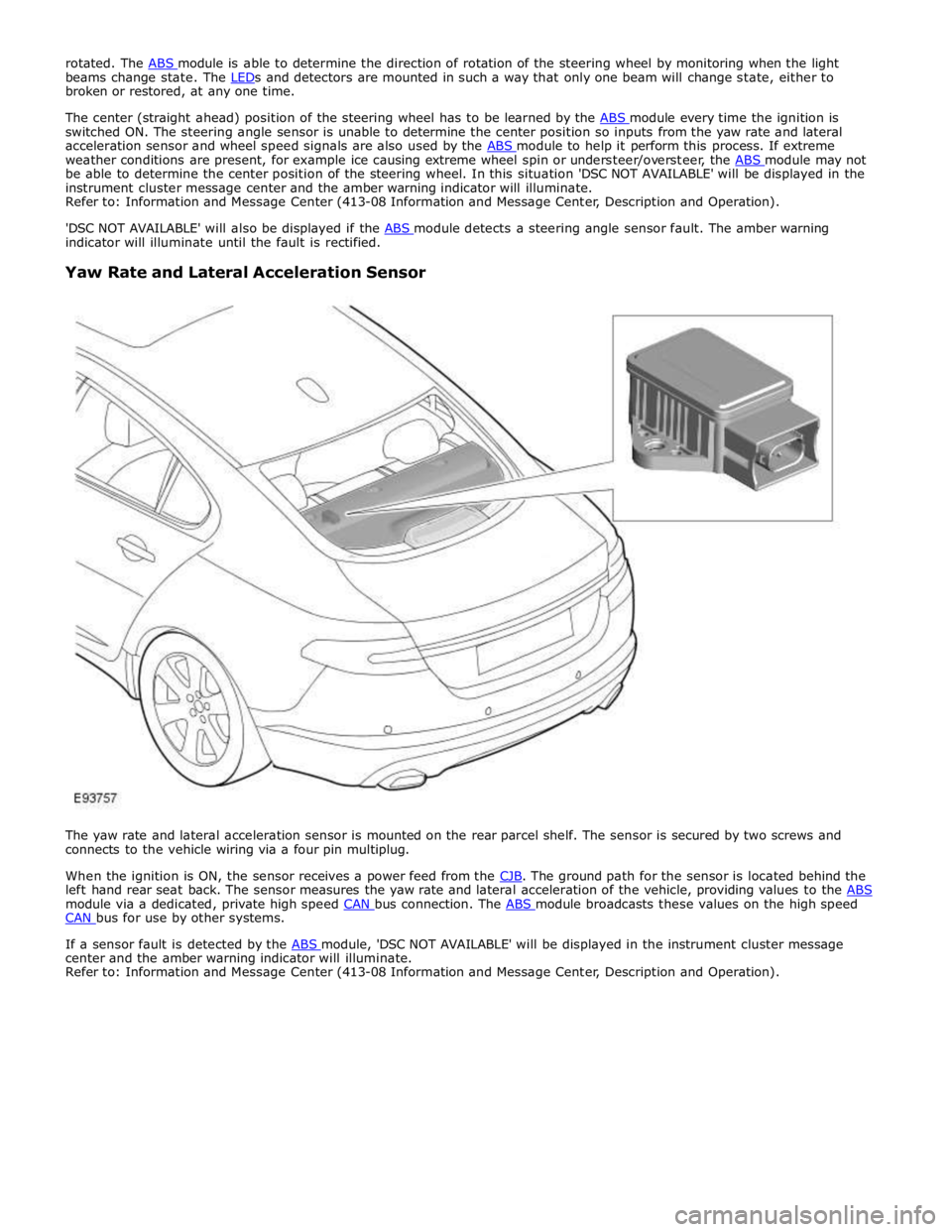
The yaw rate and lateral acceleration sensor is mounted on the rear parcel shelf. The sensor is secured by two screws and
connects to the vehicle wiring via a four pin multiplug.
When the ignition is ON, the sensor receives a power feed from the CJB. The ground path for the sensor is located behind the left hand rear seat back. The sensor measures the yaw rate and lateral acceleration of the vehicle, providing values to the ABS module via a dedicated, private high speed CAN bus connection. The ABS module broadcasts these values on the high speed CAN bus for use by other systems.
If a sensor fault is detected by the ABS module, 'DSC NOT AVAILABLE' will be displayed in the instrument cluster message center and the amber warning indicator will illuminate.
Refer to: Information and Message Center (413-08 Information and Message Center, Description and Operation).
Page 814 of 3039
engine oil).
Oil Consumption Test
The amount of oil an engine uses will vary with the way the vehicle is driven in addition to normal engine-to-engine variation.
This is especially true during the first 16,100 km (10,000 miles) when a new engine is being broken in or until certain internal
components become conditioned. Vehicles used in heavy-duty operation may use more oil. The following are examples of
heavy-duty operation:
Trailer towing applications
Severe loading applications
Sustained high speed operation
Engines need oil to lubricate the following internal components:
Cylinder block cylinder walls
Pistons and piston rings
Intake and exhaust valve stems
Intake and exhaust valve guides
All internal engine components
When the pistons move downward, a thin film of oil is left on the cylinder walls. As the vehicle is operated, some oil is also
drawn into the combustion chambers past the intake and exhaust valve stem seals and burned.
The following are examples of conditions that can affect oil consumption rates:
Engine size
Operator driving habits
Ambient temperatures
Quality and viscosity of oil
Engine is being run in an overfilled condition (check the oil level at least five minutes after a hot shutdown with the
vehicle parked on a level surface. The oil level should not be above the top of the cross-hatched area and the letter "F"
in FULL).
Operation under varying conditions can frequently be misleading. A vehicle that has been run for several thousand miles on
short trips or in below-freezing ambient temperatures may have consumed a "normal" amount of oil. However, when checking
the engine oil level, it may measure up to the full mark on the oil level indicator due to dilution (condensation and fuel) in the
engine crankcase. The vehicle then might be driven at high speeds on the highway where the condensation and fuel boil off.
The next time the engine oil is checked it may appear that a liter of oil was used in about 160 km (100 miles). Oil
consumption rate is about one liter per 2,400 km (1,500 miles).
Make sure the selected engine oil meets Jaguar specification and the recommended API performance category "SG" and SAE
viscosity grade as shown in the vehicle Owner's Guide. It is also important that the engine oil is changed at the intervals
specified for the typical operating conditions.
The following diagnostic procedure is used to determine the source of excessive oil consumption.
NOTE: Oil use is normally greater during the first 16,100 km (10,000 miles) of service. As mileage increases, oil use
decreases. High speed driving, towing, high ambient temperature and other factors may result in greater oil use.
1. Define excessive consumption, such as the number of miles driven per liter of oil used. Also determine customers
driving habits, such as sustained high speed operation, towing, extended idle and other considerations.
2. Verify that the engine has no external oil leaks as described under Engine Oil Leaks in this section.
3. Carry out an oil consumption test:
Run the engine to normal operating temperature. Switch engine OFF and allow oil to drain back for at least five
minutes .
With vehicle parked on level surface, check the engine oil level.
If required, add engine oil to set level exactly to the FULL mark.
Record the vehicle mileage.
Instruct the customer to return for a level check after driving the vehicle as usual for 1,610 km (1000 miles).
Check the oil level under the same conditions and at the same location as the initial check.
NOTE: If the oil consumption rate is unacceptable go to Step 4.
4. Check the Positive Crankcase Ventilation (PCV) system. Make sure the system is not plugged.
5. Check for plugged oil drain-back holes in the cylinder head and cylinder block.
6. If the condition still exists after carrying out the above tests go to step 9.
7. Carry out a cylinder compression test. Refer to the Compression Test procedure in this section. This can help determine
the source of oil consumption such as valves, piston rings or other areas.
8. Check valve guides for excessive guide clearance. Install new valve stem seals after verifying valve guide clearance.
9. Worn or damaged internal engine components can cause excessive oil consumption. Small deposits of oil on the tips of
the spark plugs can be a clue to internal oil consumption.
Page 1344 of 3039
Published: 11-May-2011
Evaporative Emissions - V8 5.0L Petrol/V8 S/C 5.0L Petrol - Evaporative Emissions - System Operation and Component Description
Description and Operation
System Operation DIAGNOSTIC MODULE - TANK LEAKAGE PUMP (NAS ONLY)
To check the fuel tank and the EVAP (evaporative emission) system for leaks, the ECM (engine control module) operates the
DMTL pump and monitors the current draw. Initially, the ECM establishes a reference current by pumping air through the reference orifice and back to atmosphere. Once the reference current is determined, the ECM closes the change-over valve, which seals the EVAP system. The EVAP canister purge valve remains de-energized and is therefore closed. The output from the air pump is diverted from the reference orifice and into the EVAP system.
When the change-over valve is closed, the load on the air pump falls to zero. Providing there are no leaks, the air pump will
begin to pressurize the EVAP system and the load and current draw in the pump increases. By monitoring the rate and level of the current increase, the ECM can determine if there is a leak in the EVAP system.
During normal vehicle operation, 15 seconds after the engine has started, the ECM energizes the heating element in the pump to prevent condensation formation and possible incorrect readings. The heater remains energized until either the engine and
ignition are off (if no DMTL test is running) or until after the DMTL test is completed.
Leaks are classified as:
Minor - equivalent to a hole diameter of 0.5 to 1.0 mm (0.02 to 0.04 in.).
Major - equivalent to a hole diameter of 1.0 mm (0.04 in.) or greater.
The ECM performs a check for major leaks each time the ignition is switched off, providing the following conditions are met: The vehicle speed is zero.
The engine speed is zero.
The atmospheric pressure is above 70 kPa (10.15 lbf/in2
), i.e. the altitude is less than approximately 3047 m (10000
feet).
The ambient temperature is between 0 and 40 °C (32 and 104 °F).
The EVAP canister vapor concentration factor is 5 or less (where 0 is no fuel vapor, 1 is stoichiometric fuel vapor and greater than 1 is rich fuel vapor).
The fuel tank level is valid and between 15 and 85% of nominal capacity.
The engine running time during the previous cycle was more than 10 minutes.
The battery voltage is between 10 and 15 volts.
The last engine off time was more than 180 minutes.
No errors are detected with the EVAP components, the ambient air temperature and the fuel level.
NOTE: A leak test can be performed using a Jaguar recognized diagnostic tool. This overrides the above conditions and is
useful for checking correct system and component operation.
The ECM performs a check for minor leaks after every 2nd major leak check.
When the leak check is complete, the ECM stops the DMTL pump and opens (de-energizes) the change-over valve.
If the fuel filler cap is opened or refueling is detected during the leak check, by a sudden drop in the current draw or a rise in
the fuel level, the ECM aborts the leak check.
If a leak is detected during the check, the ECM stores an appropriate fault code in its memory. If a leak is detected on two consecutive checks, the ECM illuminates the MIL (malfunction indicator lamp) in the instrument cluster on the next drive cycle. The duration of a leak check can be between 60 and 900 seconds depending on the results and fuel tank level.
EVAP CANISTER PURGE VALVE
The ECM waits until the engine is running above 55 °C (131 °F) coolant temperature with closed loop fuel operational before the purging process is activated. Under these conditions the engine should be running smoothly with no warm up enrichment.
The EVAP canister purge valve duty (and flow) is initially ramped slowly because the vapor concentration is unknown (a sudden increase in purge could cause unstable engine running or cause it to stall due to an extremely "rich" air/fuel mixture). The
concentration is then determined from the amount of adjustment that the closed loop fueling is required to make to achieve
the target AFR (air fuel ratio). Once the concentration has been determined, the purge flow can be increased rapidly and the
injected fuel can be pro-actively adjusted to compensate for the known purge vapor and the target AIR control is maintained.
When the purging process is active, fresh air is drawn into the EVAP canister via the DMTL filter and pump on NAS vehicles, or via the vent port on the EVAP canister of non NAS vehicles.
Page 1422 of 3039
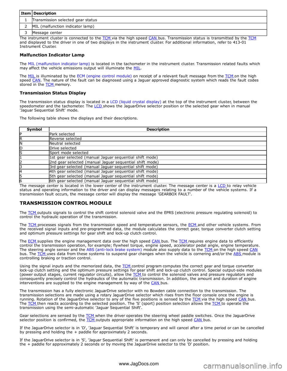
1 Transmission selected gear status 2 MIL (malfunction indicator lamp) 3 Message center The instrument cluster is connected to the TCM via the high speed CAN bus. Transmission status is transmitted by the TCM and displayed to the driver in one of two displays in the instrument cluster. For additional information, refer to 413-01
Instrument Cluster.
Malfunction Indicator Lamp
The MIL (malfunction indicator lamp) is located in the tachometer in the instrument cluster. Transmission related faults which
may affect the vehicle emissions output will illuminate the MIL.
The MIL is illuminated by the ECM (engine control module) on receipt of a relevant fault message from the TCM on the high speed CAN. The nature of the fault can be diagnosed using a Jaguar approved diagnostic system which reads the fault codes stored in the TCM memory.
Transmission Status Display
The transmission status display is located in a LCD (liquid crystal display) at the top of the instrument cluster, between the
speedometer and the tachometer. The LCD shows the JaguarDrive selector position or the selected gear when in manual 'Jaguar Sequential Shift' mode.
The following table shows the displays and their descriptions.
Symbol Description P Park selected R Reverse selected N Neutral selected D Drive selected S Sport mode selected 1 1st gear selected (manual Jaguar sequential shift mode) 2 2nd gear selected (manual Jaguar sequential shift mode) 3 3rd gear selected (manual Jaguar sequential shift mode) 4 4th gear selected (manual Jaguar sequential shift mode) 5 5th gear selected (manual Jaguar sequential shift mode) 6 6th gear selected (manual Jaguar sequential shift mode) The message center is located in the lower center of the instrument cluster. The message center is a LCD to relay vehicle status and operating information to the driver and can display messages relating to a number of the vehicle systems. If a
transmission fault occurs, the message center will display the message 'GEARBOX FAULT'.
TRANSMISSION CONTROL MODULE
The TCM outputs signals to control the shift control solenoid valve and the EPRS (electronic pressure regulating solenoid) to control the hydraulic operation of the transmission.
The TCM processes signals from the transmission speed and temperature sensors, the ECM and other vehicle systems. From the received signal inputs and pre-programmed data, the module calculates the correct gear, torque converter clutch setting
and optimum pressure settings for gear shift and lock-up clutch control.
The ECM supplies the engine management data over the high speed CAN bus. The TCM requires engine data to efficiently control the transmission operation, for example; flywheel torque, engine speed, accelerator pedal angle, engine temperature.
The steering angle sensor and the ABS (anti-lock brake system) module also supply data to the TCM on the high speed CAN bus. The TCM uses data from these systems to suspend gear changes when the vehicle is cornering and/or the ABS module is controlling braking or traction control.
Using the signal inputs and the memorized data, the TCM control program computes the correct gear and torque converter lock-up clutch setting and the optimum pressure settings for gear shift and lock-up clutch control. Special output-side modules
(power output stages, current regulator circuits), allow the TCM to control the solenoid valves and pressure regulators and consequently precisely control the hydraulics of the automatic transmission. In addition, the amount and duration of engine
interventions are supplied to the engine management by way of the CAN bus.
The transmission has a fully electronic JaguarDrive selector with no Bowden cable connection to the transmission. The
transmission selections are made using a rotary JaguarDrive selector which rises from the floor console once the engine is
running. Rotation of the JaguarDrive selector to any of the five positions is sensed by the TCM via the high speed CAN bus. The TCM then reacts according to the selected position. The 'S' (sport) position selection allows the TCM to operate the transmission using the semi-automatic 'Jaguar Sequential Shift'.
Gear selections are sensed by the TCM when the driver operates the steering wheel paddle switches. Once the JaguarDrive selector position is confirmed, the TCM outputs appropriate information on the high speed CAN bus.
If the JaguarDrive selector is in 'D', 'Jaguar Sequential Shift' is temporary and will cancel after a time period or can be cancelled
by pressing and holding the + paddle for approximately 2 seconds.
If the JaguarDrive selector is in 'S', 'Jaguar Sequential Shift' is permanent and can only be cancelled by pressing and holding
the + paddle for approximately 2 seconds or by moving the JaguarDrive selector to the 'D' position.
www.JagDocs.com
Page 1423 of 3039

The TCM can be reprogrammed using a Jaguar approved diagnostic system using a flash code. The TCM processor has a 440 kb internal flash memory. Of this capacity, approximately 370 kb are used by the basic transmission program. The remainder,
approximately 70 kb is used to store vehicle-specific application data.
Engine Stall
If the vehicle stalls it will coast down in gear, with the transmission providing drive to the engine. A restart can be attempted
at this point and the engine may start and the driver can continue.
If the coast down speed reduces such that the speed of the engine is less than 600 rev/min, the transmission will go to
neutral, D illumination will flash in the instrument cluster. The driver needs to select neutral or park and then press the brake
pedal to restart the engine.
If the start/stop button is pressed when driving, the message ENGINE STOP BUTTON PRESSED is displayed in the message
center but there will be no change to the ignition state. If the driver requires to switch off the engine, the start/stop button
must be pressed for a second time. The engine will be stopped and will be back driven by the transmission as the vehicle
coasts down. When the engine speed is less than 600 rev/min the transmission engages neutral (flashing D illumination in the
instrument cluster). When vehicle speed is less than 2 km/h (1.2 mph) Park is engaged. The JaguarDrive selector automatically
rotates back to its lowered P position and the vehicle ignition is switched off.
The park engagement is prevented in a stall case as the ignition power is on and D was the last selected gear. The park
engagement speed at ignition off is from the least value of the wheel speeds (CAN signal) and transmission output speed (internal signal).
TRANSMISSION Component Description
The transmission comprises the main casing which houses all of the transmission components. The main casing also
incorporates an integral bell housing.
A fluid pan is attached to the lower face of the main casing and is secured with bolts. The fluid pan is sealed to the main
casing with a gasket. Removal of the fluid pan allows access to the Mechatronic valve block. The fluid pan has a magnet
located around the drain plug which collects any metallic particles present in the transmission fluid.
A fluid filter is located inside the fluid pan. If the transmission fluid becomes contaminated or after any service work, the fluid
pan with integral filter must be replaced.
The integral bell housing provides protection for the torque converter assembly and also provides the attachment for the
gearbox to the engine cylinder block. The torque converter is a non-serviceable assembly which also contains the lock-up clutch
mechanism. The torque converter drives a crescent type pump via drive tangs. The fluid pump is located in the main casing,
behind the torque converter.
The main casing contains the following major components:
Input shaft
Output shaft
Mechatronic valve block which contains the solenoids, speed sensors and the TCM Three rotating multiplate drive clutches
Two fixed multiplate brake clutches
A single planetary gear train and a double planetary gear train.
Page 1532 of 3039
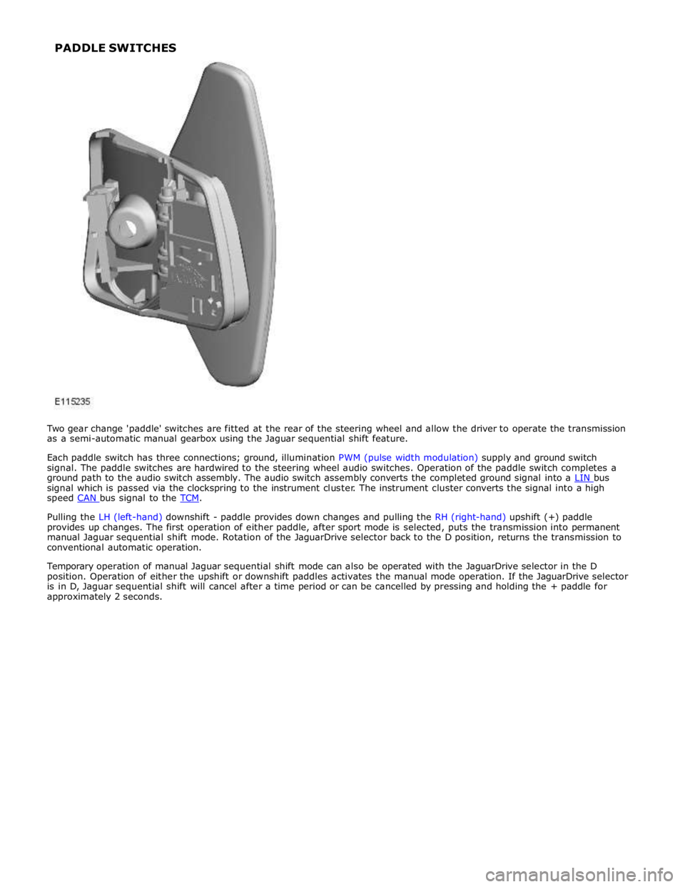
signal which is passed via the clockspring to the instrument cluster. The instrument cluster converts the signal into a high
speed CAN bus signal to the TCM.
Pulling the LH (left-hand) downshift - paddle provides down changes and pulling the RH (right-hand) upshift (+) paddle
provides up changes. The first operation of either paddle, after sport mode is selected, puts the transmission into permanent
manual Jaguar sequential shift mode. Rotation of the JaguarDrive selector back to the D position, returns the transmission to
conventional automatic operation.
Temporary operation of manual Jaguar sequential shift mode can also be operated with the JaguarDrive selector in the D
position. Operation of either the upshift or downshift paddles activates the manual mode operation. If the JaguarDrive selector
is in D, Jaguar sequential shift will cancel after a time period or can be cancelled by pressing and holding the + paddle for
approximately 2 seconds. PADDLE SWITCHES
Page 1589 of 3039
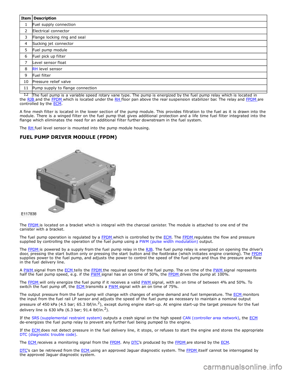
1 Fuel supply connection 2 Electrical connector 3 Flange locking ring and seal 4 Sucking jet connector 5 Fuel pump module 6 Fuel pick up filter 7 Level sensor float 8 RH level sensor 9 Fuel filter 10 Pressure relief valve 11 Pump supply to flange connection 12 The fuel pump is a variable speed rotary vane type. The pump is energized by the fuel pump relay which is located in the RJB and the FPDM which is located under the RH floor pan above the rear suspension stabilizer bar. The relay and FPDM are controlled by the ECM.
A fine mesh filter is located in the lower section of the pump module. This provides filtration to the fuel as it is drawn into the
module. There is a winged filter on the fuel pump that gives additional protection and a life time fuel filter integrated into the
flange which eliminates the need for an additional filter further downstream in the fuel system.
The RH fuel level sensor is mounted into the pump module housing.
FUEL PUMP DRIVER MODULE (FPDM)
The FPDM is located on a bracket which is integral with the charcoal canister. The module is attached to one end of the canister with a bracket.
The fuel pump operation is regulated by a FPDM which is controlled by the ECM. The FPDM regulates the flow and pressure supplied by controlling the operation of the fuel pump using a PWM (pulse width modulation) output.
The FPDM is powered by a supply from the fuel pump relay in the RJB. The fuel pump relay is energized on opening the driver's door, pressing the start button only or pressing the start button and the footbrake (which initiates engine cranking). The FPDM supplies power to the fuel pump, and adjusts the power to control the speed of the fuel pump and thus the pressure and flow
in the fuel delivery line.
A PWM signal from the ECM tells the FPDM the required speed for the fuel pump. The on time of the PWM signal represents half the fuel pump speed, e.g. if the PWM signal has an on time of 50%, the FPDM drives the pump at 100%.
The FPDM will only energize the fuel pump if it receives a valid PWM signal, with an on time of between 4% and 50%. To switch the fuel pump off, the ECM transmits a PWM signal with an on time of 75%.
The output pressure from the fuel pump will change with changes of engine demand and fuel temperature. The ECM monitors the input from the fuel rail LP sensor and adjusts the speed of the fuel pump as necessary to maintain a nominal output
pressure of 450 kPa (4.5 bar; 65.3 lbf/in.2
), except during engine start-up. At engine start-up the target pressure for the fuel
delivery line is 630 kPa (6.3 bar; 91.4 lbf/in.2
).
If the SRS (supplemental restraint system) outputs a crash signal on the high speed CAN (controller area network), the ECM de-energizes the fuel pump relay to prevent any further fuel being pumped to the engine.
If the ECM does not detect pressure in the fuel delivery line, it stops, or refuses to start the engine and stores the appropriate DTC (diagnostic trouble code).
The ECM receives a monitoring signal from the FPDM. Any DTC's produced by the FPDM are stored by the ECM.
DTC's can be retrieved from the ECM using an approved Jaguar diagnostic system. The FPDM itself cannot be interrogated by the approved Jaguar diagnostic system.
Page 1595 of 3039
Published: 28-Jul-2014
Fuel Tank and Lines - V8 5.0L Petrol/V8 S/C 5.0L Petrol - Fuel Tank and
Lines
Diagnosis and Testing
Principle of Operation
For a detailed description of the fuel tank and lines system and operation, refer to the relevant Description and Operation
section of the workshop manual. REFER to: (310-01C Fuel Tank and Lines - V8 5.0L Petrol/V8 S/C 5.0L Petrol)
Fuel Tank and Lines (Description and Operation), Fuel Tank and Lines (Description and Operation), Fuel Tank and Lines (Description and Operation).
Inspection and Verification
WARNINGS:
Eye protection must be worn at all times when working on or near any fuel related components. Failure to follow this
instruction may result in personal injury.
This procedure involves fuel handling. Be prepared for fuel spillage at all times and always observe fuel handling
precautions. Failure to follow this instruction may result in personal injury.
After carrying out repairs, the fuel system must be checked visually for leaks. This should be done after the engine has
been run, but with the engine switched OFF. Failure to follow this instruction may result in personal injury.
If taken internally, DO NOT induce vomiting. Seek immediate medical attention. Failure to follow this instruction may
result in personal injury.
If fuel contacts the eyes, flush the eyes with cold water or eyewash solution and seek medical attention. Failure to follow
this instruction may result in personal injury.
Wash hands thoroughly after handling, as prolonged contact may cause irritation. Should irritation develop, seek medical
attention. Failure to follow this instruction may result in personal injury.
CAUTIONS:
Before disconnecting any part of the system, it is imperative that all dust, dirt and debris is removed from around
components to prevent ingress of foreign matter into the fuel system. Failure to follow this instruction may result in damage to
the vehicle.
It is essential that absolute cleanliness is observed when working with these components. Always install blanking plugs
to any open orifices or lines. Failure to follow this instruction may result in damage to the vehicle.
Diagnosis by substitution from a donor vehicle is NOT acceptable. Substitution of control modules does not guarantee
confirmation of a fault, and may also cause additional faults in the vehicle being tested and/or the donor vehicle.
NOTES:
Check and rectify basic faults before beginning diagnostic routines involving pinpoint tests.
When measuring fuel sender resistance values with a multimeter, it is critical to use the correct multimeter setting. The
multimeter should not be on the 'Auto' setting and must be set to 'Manual'. This will help prevent incorrect diagnosis and
unnecessary replacement of fuel senders. If the multimeter range is set at 'Auto' then, during a sweep of the sender from 50
Ohms to 998 Ohms, the multimeter has to change its measurement range. For approximately 1 second, during the range switch
over point, the multimeter display indicates an open circuit. This can lead to a mis-diagnosis of a fuel sender fault.
1. Verify the customer concern
2. Visually inspect for obvious signs of damage and system integrity