seat control module JAGUAR XFR 2010 1.G Owner's Guide
[x] Cancel search | Manufacturer: JAGUAR, Model Year: 2010, Model line: XFR, Model: JAGUAR XFR 2010 1.GPages: 3039, PDF Size: 58.49 MB
Page 1711 of 3039
rear window heater switch is pressed or the engine stops.
Automatic operation during a journey is initiated when low ambient air temperatures are experienced and the vehicle has been
travelling for a set period of time above a threshold speed. In this instance, no feedback is given to the driver to inform him
the rear window heater is operational (the switch LED is not illuminated). The duration of heater operation is variable depending on the ambient air temperature, vehicle speed and the amount of time the vehicle has been travelling.
Windshield Heater (Where Fitted)
Windshield heater operation is only enabled when the engine is running. The ATC module controls operation of the windshield heater using two relays in the EJB (engine junction box). When windshield heater operation is required, the ATC module broadcasts a message to the CJB on the medium speed CAN bus. On receipt of the message, the CJB energizes the relays by providing a ground path for both relay coils. This allows a battery feed to flow across the relays to power the windshield left
and right heater elements.
There are two modes of windshield heater operation; manual and automatic.
Manual operation is activated by pressing the windshield heater switch on the integrated control panel. When the switch is
pressed, the status LED in the switch illuminates and the windshield heater elements are energized. Manual operation is discontinued when the windshield heater switch is pressed a second time, 5 minutes have elapsed (the heating phase), or the
engine stops. If manual operation is discontinued by the engine stopping, the previous heating phase is resumed if the engine
is re-started within 30 seconds.
There are two variants of automatic operation; automatic operation at the start of a journey and automatic operation during a
journey.
Automatic operation at the start of a journey is initiated if the ambient air temperature is below 5 °C (41 °F). In this instance,
the switch LED is illuminated and the heater elements are energized for 6.5 minutes. Automatic operation is discontinued if the windshield heater switch is pressed or the engine stops.
Automatic operation during a journey is initiated when low ambient air temperatures are experienced and the vehicle has been
travelling for a set period of time above a threshold speed. In this instance, no feedback is given to the driver to inform him
the windshield heater is operational (the switch LED is not illuminated) and the duration of operation is variable depending upon the ambient air temperature, vehicle speed and the amount of time the vehicle has been travelling.
Exterior Mirror Heaters
Operation of the exterior mirror heaters is fully automatic and not controllable by the driver. Exterior mirror heater operation is
determined by ambient air temperature and windshield wiper status. When ambient air temperature reaches a pre-determined
level, the ATC module broadcasts an exterior mirror heating request to the door modules over the medium speed CAN bus. On receipt of this message, the door modules provide feed and ground connections to both exterior mirror heater elements.
The amount of time the exterior mirror heaters are operational increases if the windshield wipers are switched on. This ensures
the mirrors remain mist free in damp and wet conditions, where there is an increased risk of misting.
Seat Heaters (Where Fitted)
There are four seat heater settings available; off, 1, 2 and 3, which can be selected on the home and climate control screens
of the TSD. The heat setting is relayed to the vehicle occupants through a graduated display on the TSD.
Operation of the heated seats is controlled by the ATC module. When the ATC module receives a heating request from the TSD, it broadcasts a message to the CJB over the medium speed CAN bus. The CJB then provides a hardwired 12 V supply to the three heater elements in the related front seat. The heater elements, two in the seat cushion and one in the seat squab,
are wired in series. The ATC module monitors seat temperature using a temperature sensor located in each seat cushion. The CJB provides the temperature sensors with a 5 V supply. The level of the returned voltage back to the CJB is proportional to the seat temperature. The value of the return signal is broadcast to the ATC module, over the medium speed CAN bus, which allows it to control the seat temperature to the required level. The ATC module will suspend or disable operation of the seat heaters if any of the following occur:
Battery voltage exceeds 16.5 ± 0.3 V for more than 5 seconds. Seat heating is re-enabled when battery voltage
decreases to 16.2 ± 0.3 V.
If a short or open circuit is detected.
If the seat heat temperature rises significantly above the target temperature setting.
The graduated display on the TSD remains illuminated until the seat heaters are turned off or the engine stops. If the engine
is restarted within 30 seconds the seat heater resumes the previous heating level.
Page 1767 of 3039
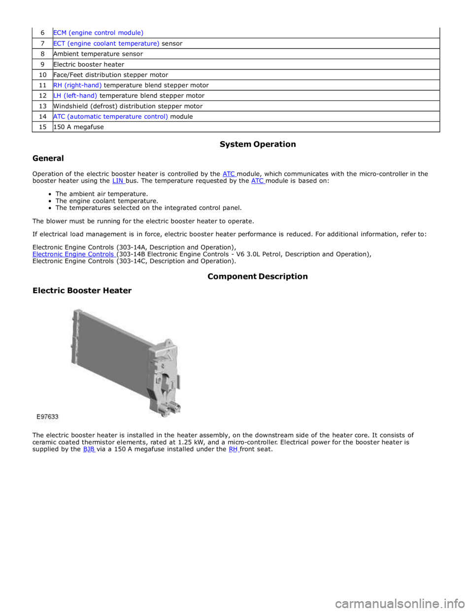
7 ECT (engine coolant temperature) sensor 8 Ambient temperature sensor 9 Electric booster heater 10 Face/Feet distribution stepper motor 11 RH (right-hand) temperature blend stepper motor 12 LH (left-hand) temperature blend stepper motor 13 Windshield (defrost) distribution stepper motor 14 ATC (automatic temperature control) module 15 150 A megafuse
General System Operation
Operation of the electric booster heater is controlled by the ATC module, which communicates with the micro-controller in the booster heater using the LIN bus. The temperature requested by the ATC module is based on:
The ambient air temperature.
The engine coolant temperature.
The temperatures selected on the integrated control panel.
The blower must be running for the electric booster heater to operate.
If electrical load management is in force, electric booster heater performance is reduced. For additional information, refer to:
Electronic Engine Controls (303-14A, Description and Operation),
Electronic Engine Controls (303-14B Electronic Engine Controls - V6 3.0L Petrol, Description and Operation), Electronic Engine Controls (303-14C, Description and Operation).
Electric Booster Heater Component Description
The electric booster heater is installed in the heater assembly, on the downstream side of the heater core. It consists of
ceramic coated thermistor elements, rated at 1.25 kW, and a micro-controller. Electrical power for the booster heater is
supplied by the BJB via a 150 A megafuse installed under the RH front seat.
Page 1784 of 3039
7 Instrument cluster 8 Steering column motor 9 High speed CAN bus connection to other vehicle systems 10 Engine oil pressure switch 11 Steering column adjustment switch 12 Brake fluid level switch 13 LH (left-hand) steering column multifunction switch 14 Start control module 15 Clockspring 16 RH (right-hand) steering column multifunction switch 17 Engine coolant level sensor 18 Auxiliary lighting switch
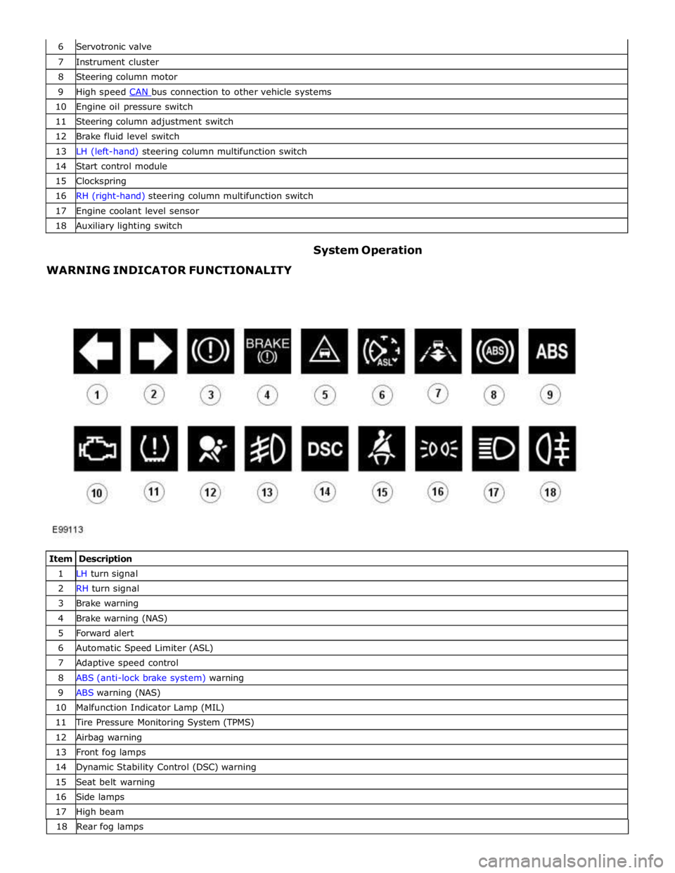
WARNING INDICATOR FUNCTIONALITY System Operation
Item Description 1 LH turn signal 2 RH turn signal 3 Brake warning 4 Brake warning (NAS) 5 Forward alert 6 Automatic Speed Limiter (ASL) 7 Adaptive speed control 8 ABS (anti-lock brake system) warning 9 ABS warning (NAS) 10 Malfunction Indicator Lamp (MIL) 11 Tire Pressure Monitoring System (TPMS) 12 Airbag warning 13 Front fog lamps 14 Dynamic Stability Control (DSC) warning 15 Seat belt warning 16 Side lamps 17 High beam 18 Rearfoglamps
Page 1787 of 3039
the RCM and illuminated by the instrument cluster on receipt of high speed CAN bus messages. The safety belt warning indicator is not subject to the 3 second indicator check when the ignition is switched on.
The operation of the passenger seat buckle switch is as described below with the exception that the instrument cluster must
receive a hardwired signal from the belt minder control module to indicate that a passenger is occupying the seat.
The safety belt warning indicator is subject to a timer. The warning indicator is activated when the following conditions exist:
Ignition is switched on
One of the front seat belts is unbuckled
USA market only - 75 seconds has elapsed after ignition on mode is selected
Vehicle is not in reverse gear
Vehicle speed is more than 8 km/h (5 mph).
Once the above parameters are met, the instrument cluster flashes the warning indicator at 2 Hz for 10 seconds accompanied
by a simultaneous chime. After 10 seconds the chime ceases and the warning indicator is permanently illuminated for 20
seconds. This sequence is repeated every 30 seconds until one of the following events occurs:
300 seconds has elapsed
The safety belt of the occupied front seats is fastened
The ignition is switched to off mode
The vehicle speed decreases to below 5 km/h (3 mph).
NOTE: On USA market vehicles, the warning indicator in not permanently illuminated.
The safety belt minder function cannot be disabled. The seat belt minder function can be disabled.
Refer to: Safety Belt System (501-20A Safety Belt System, Description and Operation). 14. Side Lamp Indicator
The instrument cluster controls the green colored side lamp indicator on receipt of a side lamp status message on the medium
speed CAN bus from the CJB and the auxiliary junction box. The lighting switch on the LH steering column multifunction switch is connected to the instrument cluster. Selections using this switch are detected by the cluster which requests the side or
headlamp operation via a message to the CJB and the RJB. The CJB and the RJB responds with a side lamp active message and the cluster illuminates the side lamp indicator. The side lamp indicator is not subject to the 3 second indicator check when
the ignition is switched on.
15. High Beam Indicator
The instrument cluster controls the blue colored high beam indicator on receipt of a high beam status message on the medium
speed CAN bus from the CJB. The lighting switch on the LH steering column multifunction switch is connected to the instrument cluster. High beam or flash selections using this switch are detected by the cluster which requests the light
operation via a CAN message to the CJB. The CJB responds with a high beam active message and the cluster illuminates the high beam indicator. The high beam indicator is not subject to the 3 second indicator check when the ignition is switched on.
16. Rear Fog Lamp Indicator
The amber colored rear fog lamp indicator is controlled by the auxiliary junction box and illuminated by the instrument cluster
on receipt of a rear fog lamp on message on the medium speed CAN bus from the RJB. The indicator is illuminated for as long as the rear fog lamps are active. The rear fog lamp indicator is not subject to the 3 second indicator check when the ignition is
switched on.
SPEEDOMETER
The speedometer is driven by high speed CAN signals transmitted by the ABS module. The wheel speeds are measured by sensors reading the rotational speed of the rear wheels from toothed targets on the hubs. An average of the two wheel speeds
are passed from the sensors to the ABS module in the form of pulsed signals. The ABS module converts these signals into a speed output on the high speed CAN to the instrument cluster. The same speed outputs from the wheel speed sensors are also used to calculate the distance the vehicle has travelled.
TACHOMETER
The tachometer is driven by an engine speed signal transmitted on the high speed CAN from the ECM. The signal is derived from the CKP (crankshaft position) sensor. The signal is received by the instrument cluster microprocessor and the output from
the microprocessor drives the tachometer.
FUEL GAGE
The fuel gage is controlled by CAN messages from the RJB. The RJB reads the values output by the fuel level sensors every 131 ms and transmits a fuel tank contents value, corrected for battery voltage, in a CAN message to the instrument cluster. A fuel pump symbol is displayed to the left of the linear gage. An arrow above the symbol shows the driver on which side of the
vehicle the fuel filler cap is located. Above the linear fuel gage, is a LCD (liquid crystal display) area which displays odometer
and trip readouts. When a trip computer function is selected, these are replaced by a trip computer display for the trip function
selected.
LIQUID CRYSTAL DISPLAY
In the area above and below the message center is a LCD display. The area below the message center displays a linear fuel www.JagDocs.com
Page 1788 of 3039
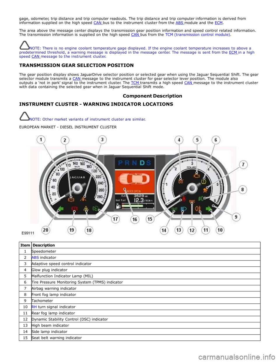
gage, odometer, trip distance and trip computer readouts. The trip distance and trip computer information is derived from
information supplied on the high speed CAN bus to the instrument cluster from the ABS module and the ECM.
The area above the message center displays the transmission gear position information and speed control related information.
The transmission information is supplied on the high speed CAN bus from the TCM (transmission control module).
NOTE: There is no engine coolant temperature gage displayed. If the engine coolant temperature increases to above a
predetermined threshold, a warning message is displayed in the message center. The message is sent from the ECM in a high speed CAN message to the instrument cluster.
TRANSMISSION GEAR SELECTION POSITION
The gear position display shows JaguarDrive selector position or selected gear when using the Jaguar Sequential Shift. The gear
selector module transmits a CAN message to the instrument cluster for gear selector lever position. The module also outputs a 'not in park' signal to the instrument cluster. The TCM transmits a high speed CAN message to the instrument cluster with data containing the selected gear when in Jaguar Sequential Shift mode.
Component Description INSTRUMENT CLUSTER - WARNING INDICATOR LOCATIONS
NOTE: Other market variants of instrument cluster are similar.
EUROPEAN MARKET - DIESEL INSTRUMENT CLUSTER
Item Description 1 Speedometer 2 ABS indicator 3 Adaptive speed control indicator 4 Glow plug indicator 5 Malfunction Indicator Lamp (MIL) 6 Tire Pressure Monitoring System (TPMS) indicator 7 Airbag warning indicator 8 Front fog lamp indicator 9 Tachometer 10 RH turn signal indicator 11 Rear fog lamp indicator 12 Dynamic Stability Control (DSC) indicator 13 High beam indicator 14 Side lamp indicator 15 Seat belt warning indicator
Page 1789 of 3039

17 Automatic Speed Limiter (ASL) indicator 18 Forward alert indicator 19 Brake warning indicator 20 LH turn signal indicator NAS MARKET - V8 NORMALLY ASPIRATED INSTRUMENT CLUSTER
Item Description 1 Speedometer 2 ABS indicator (NAS) 3 ABS indicator (ROW) 4 Adaptive speed control indicator 5 Tachometer 6 Malfunction Indicator Lamp (MIL) 7 Tire Pressure Monitoring System (TPMS) indicator 8 Airbag warning indicator 9 Front fog lamp indicator 10 RH turn signal indicator 11 Rear fog lamp indicator 12 Dynamic Stability Control (DSC) indicator 13 High beam indicator 14 Seat belt warning indicator 15 Side lamp indicator 16 Message center 17 Automatic Speed Limiter (ASL) indicator 18 Forward alert indicator 19 Brake warning indicator (NAS) 20 Brake warning indicator (ROW) 21 LH turn signal indicator The warning indicators are located in various positions in the instrument cluster. The indicators can be split into two groups;
instrument cluster controlled and externally controlled.
Instrument cluster controlled warning indicators are dependent on software logic within the instrument cluster for activation.
The cluster software controls the indicator illumination check at ignition on (power mode 6).
Externally controlled indicators are supplied with current from another vehicle system control module or illuminated by the
instrument cluster software on receipt of a bus message from another vehicle sub-system. The indicator illumination check at
ignition on (powermode 6) is also controlled by the sub-system module for these indicators.
Page 1796 of 3039

ETM Test/no. Message Center Display Gauge/Indicator/Display
Tested.
Range
Description 25:XXX -
XXXX
26:XXX -
XXXX
27.XXX -
XXXX 25 - Passenger seat belt
26 - Not used
27 - On-board temp ref 18 - Analogue
Inputs.
ANALOG
INPUTS.
#: RAW -
Ratio
28:XXX -
XXXX
29:XXX -
XXXX
30:XXX -
XXXX
31.XXX -
XXXX Cluster inputs. TDB.
Displays Hex coding of inputs 28 -
31.
28 - On-board temp
29 - Not used
30 - Not used
31 - Not used 19 -
Speedometer. SPEEDOMETER.
RAW:
MPH:
KMH:
DRIVER: Speedometer inputs. .
Displays present .
Speedometer inputs values;
Speedometer will indicate
present road speed. 20 -
Tachometer. TACHOMETER.
RAW:
ACTUAL:
DRIVER: Tachometer inputs. .
Displays present received
Tachometer input values,
tachometer will indicate present
engine RPM. 21 - Fuel
system. FUEL SYSTEM.
(A) (B)
RAW: X X
FILT: X X
PERCENT: X X Fuel indication system. .
Displays present received fuel level
A/D inputs in decimal, fuel gauge
will indicate present filtered level. 22 - Battery
voltage. BATTERY VOLTAGE.
LOCAL:
VEHICLE:
RAW:
A/D: Battery voltage. .
Displays present received battery
input voltage values. If message not
received or invalid display will be '_
_ _'. 23 - Rolling
counts. ROLLING COUNTS.
ODO:
FUEL: Odometer and fuel gauge. 0 - 255.
Displays present received odometer
and fuel level input values in
decimal, value is a rolling count. If
either message not received or
invalid respective display will be ' _
_ _' . 24 - VAPS. VAPS.
CURRENT:
COMMAND:
STATUS: Variable assistance power
steering (VAPS) status. .
CURRENT is displayed in mA.
COMMAND is last command sent to
VAPS chip. STATUS is last status
returned from VAPS chip. 25 - Module MODULE STATUS. Provides status of; Ignition
CONNECTED
Communication (Coms) ok status. (IGN), Dynamic Stability Control IGN
(DSC), Adaptive Cruise Control WAITING Coms not received, not an DSC
(ACC) and Adaptive damping MISSING issue ACC
control module (ADCM) modules. FAULTY. Coms never received ADCM Coms error . 26 - Module MODULE STATUS. Provides status of; Electronic
CONNECTED
Communication (Coms) ok status. park brake (EPB), Pedestrian EPB
Impact ECU (PIE), Restraints WAITING Coms not received, not an PIE
control module (RCM) and MISSING issue RCM
Traction control module (TCM), FAULTY. Coms never received TCM
modules.. Coms error . 27 - Module
status. MODULE STATUS.
ECM
RCC Provides status of; Engine
control module (ECM), Rear
Climate Control (RCC), Driver
Door Control (DDC) and
CONNECTED
WAITING
MISSING
Communication (Coms) ok
Coms not received, not an
issue
Page 1797 of 3039
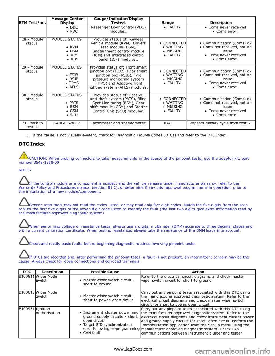
ETM Test/no. Message Center Display Gauge/Indicator/Display
Tested.
Range
Description DDC
PDC Passenger Door Control (PDC)
modules.. FAULTY.
Coms never received
Coms error . 28 - Module MODULE STATUS. Provides status of; Keyless
CONNECTED
Communication (Coms) ok status. vehicle module (KVM), Drivers KVM
seat module (DSM), WAITING Coms not received, not an DSM
Infotainment control module MISSING issue ICM
(ICM) and Integrated control FAULTY. Coms never received ICP
panel (ICP) modules.. Coms error . 29 - Module MODULE STATUS. Provides status of; Front smart
CONNECTED
Communication (Coms) ok status. junction box (FSJB), Rear smart FSJB
junction box (RSJB), Tyre WAITING Coms not received, not an RSJB
pressure monitoring system MISSING issue TPMS
(TPMS) and Adaptive front FAULTY. Coms never received AFLS
lighting system (AFLS) modules. Coms error . 30 - Module MODULE STATUS. Provides status of; Passive
CONNECTED
Communication (Coms) ok status. anti-theft system (PATS), Blind PATS
Spot Monitoring (BSM), Gear WAITING Coms not received, not an BSM
shift module (GSM) and Starter MISSING issue GSM
Control Unit (SCU) modules. FAULTY. Coms never received SCU Coms error . 31- Back to
test 2. GAUGE SWEEP. Tachometer and speedometer. N/A. Repeats display cycle from test 2.
1. If the cause is not visually evident, check for Diagnostic Trouble Codes (DTCs) and refer to the DTC Index.
DTC Index
CAUTION: When probing connectors to take measurements in the course of the pinpoint tests, use the adaptor kit, part
number 3548-1358-00
NOTES:
If the control module or a component is suspect and the vehicle remains under manufacturer warranty, refer to the
Warranty Policy and Procedures manual (section B1.2), or determine if any prior approval programme is in operation, prior to
the installation of a new module/component.
Generic scan tools may not read the codes listed, or may read only five digit codes. Match the five digits from the scan
tool to the first five digits of the seven digit code listed to identify the fault (the last two digits give extra information read by
the manufacturer-approved diagnostic system).
When performing voltage or resistance tests, always use a digital multimeter (DMM) accurate to three decimal places and
with a current calibration certificate. When testing resistance, always take the resistance of the DMM leads into account.
Check and rectify basic faults before beginning diagnostic routines involving pinpoint tests.
If DTCs are recorded and, after performing the pinpoint tests, a fault is not present, an intermittent concern may be the
cause. Always check for loose connections and corroded terminals.
DTC Description Possible Cause Action B100811
Wiper Mode
Switch
Master wiper switch circuit -
short to ground Refer to the electrical circuit diagrams and check master
wiper switch circuit for short to ground B100815
Wiper Mode
Switch
Master wiper switch circuit -
short to power, open circuit Carry out any pinpoint tests associated with this DTC using
the manufacturer approved diagnostic system. Refer to the
electrical circuit diagrams and check master wiper switch
circuit for short to power, open circuit B100951
Ignition
Authorisation
Instrument cluster power and
ground supply circuits - short,
open circuit
Target SID synchronization
error following re-programming
CAN fault Carry out any pinpoint tests associated with this DTC using
the manufacturer approved diagnostic system. Refer to the
electrical circuit diagrams and check instrument cluster power
and ground supply circuits for short, open circuit. Perform the
Immobilisation application from the Set-up menu using the
manufacturer approved diagnostic system. Check CAN
communications between instrument cluster and tester www.JagDocs.com
Page 1805 of 3039

DTC Description Possible Cause Action U013900
Lost
Communication
with Suspension
Control Module 'B'
Loss of CAN communication
with adaptive damping module Carry out any pinpoint tests associated with this DTC using
the manufacturer approved diagnostic system. Check
adaptive damping module for DTCs and refer to the relevant
DTC Index U014000
Lost
Communication
With Body
Control Module
Loss of CAN communication
with CJB Carry out any pinpoint tests associated with this DTC using
the manufacturer approved diagnostic system. Check CJB for
DTCs and refer to the relevant DTC Index U014200
Lost
Communication
With Body
Control Module
"B"
Loss of CAN communication
with RJB Carry out any pinpoint tests associated with this DTC using
the manufacturer approved diagnostic system. Check RJB for
DTCs and refer to the relevant DTC Index U015100
Lost
Communication
With Restraints
Control Module
Loss of CAN communication
with RCM Carry out any pinpoint tests associated with this DTC using
the manufacturer approved diagnostic system. Check RCM for
DTCs and refer to the relevant DTC Index U015600
Lost
Communication
with Information
Centre 'A'
Loss of CAN communication
with information and
entertainment control module Carry out any pinpoint tests associated with this DTC using
the manufacturer approved diagnostic system. Check
information and entertainment control module for DTCs and
refer to the relevant DTC Index U016400
Lost
Communication
with HVAC
Control Module
Loss of CAN communication
with climate control module Carry out any pinpoint tests associated with this DTC using
the manufacturer approved diagnostic system. Check climate
control module for DTCs and refer to the relevant DTC Index U019900
Lost
Communication
with Door Control
Module 'A'
Loss of CAN communication
with driver door module (DDM) Carry out any pinpoint tests associated with this DTC using
the manufacturer approved diagnostic system. Check DDM for
DTCs and refer to the relevant DTC Index U020000
Lost
Communication
with Door Control
Module 'B'
Loss of CAN communication
with passenger door module
(PDM) Carry out any pinpoint tests associated with this DTC using
the manufacturer approved diagnostic system. Check PDM for
DTCs and refer to the relevant DTC Index U020800
Lost
Communication
with Seat Control
Module 'A'
Loss of CAN communication
with driver seat module (DSM) Carry out any pinpoint tests associated with this DTC using
the manufacturer approved diagnostic system. Check DSM for
DTCs and refer to the relevant DTC Index U021400
Lost
Communication
with Remote
Function
Actuation
Loss of CAN communication
with keyless vehicle module
(KVM) Carry out any pinpoint tests associated with this DTC using
the manufacturer approved diagnostic system. Check KVM for
DTCs and refer to the relevant DTC Index U024100
Lost
Communication
with Headlamp
Control Module 'A'
Loss of CAN communication
with headlamp control module Carry out any pinpoint tests associated with this DTC using
the manufacturer approved diagnostic system. Check
headlamp control module for DTCs and refer to the relevant
DTC Index U025000
Lost
Communication
with Impact
Classification System Module
Loss of CAN communication
with pedestrian protection
module Carry out any pinpoint tests associated with this DTC using
the manufacturer approved diagnostic system. Check
pedestrian protection module for DTCs and refer to the
relevant DTC Index U025600
Lost
Communication
with Front
Controls Interface
Module 'A'
Loss of CAN communication
with integrated control panel Carry out any pinpoint tests associated with this DTC using
the manufacturer approved diagnostic system. Check
integrated control panel for DTCs and refer to the relevant
DTC Index U030000
Internal Control
Module Software
Incompatibility
Invalid configuration message
is received Re-configure the RJB using the manufacturer approved
diagnostic system. Clear the DTC and retest. If the DTC is
still logged suspect the instrument cluster, refer to the new
module/component installation note at the top of the DTC
Index U040268
Invalid data
received from
TCM
Algorithm based failures -
events information Check TCM for DTCs and refer to the relevant DTC Index U200411
Auxiliary Switch
Pack
Auxiliary switch signal circuit -
short to ground Refer to the electrical circuit diagrams and check auxiliary
switch signal circuit for short to ground U200415
Auxiliary Switch
Pack
Auxiliary switch signal circuit -
short to power, open circuit Carry out any pinpoint tests associated with this DTC using
the manufacturer approved diagnostic system. Refer to the
electrical circuit diagrams and check auxiliary switch signal
circuit for short to power, open circuit
Page 1827 of 3039
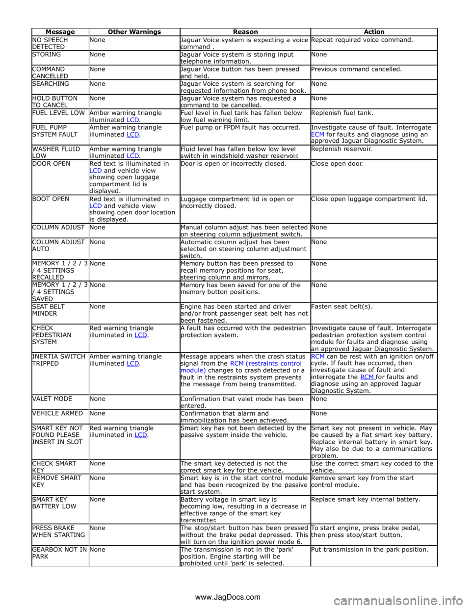
NO SPEECH
DETECTED None
Jaguar Voice system is expecting a voice
command . Repeat required voice command. STORING None
Jaguar Voice system is storing input telephone information. None COMMAND
CANCELLED None
Jaguar Voice button has been pressed
and held. Previous command cancelled. SEARCHING None
Jaguar Voice system is searching for requested information from phone book. None HOLD BUTTON TO CANCEL None
Jaguar Voice system has requested a
command to be cancelled. None FUEL LEVEL LOW
Amber warning triangle
illuminated LCD. Fuel level in fuel tank has fallen below
low fuel warning limit. Replenish fuel tank. FUEL PUMP
SYSTEM FAULT Amber warning triangle
illuminated LCD. Fuel pump or FPDM fault has occurred.
Investigate cause of fault. Interrogate
ECM for faults and diagnose using an approved Jaguar Diagnostic System. WASHER FLUID
LOW Amber warning triangle
illuminated LCD. Fluid level has fallen below low level
switch in windshield washer reservoir. Replenish reservoir. DOOR OPEN
Red text is illuminated in
LCD and vehicle view Door is open or incorrectly closed. Close open door. showing open luggage
compartment lid is
displayed. BOOT OPEN
Red text is illuminated in
LCD and vehicle view Luggage compartment lid is open or incorrectly closed. Close open luggage compartment lid. showing open door location
is displayed. COLUMN ADJUST None
Manual column adjust has been selected
on steering column adjustment switch. None COLUMN ADJUST
AUTO None
Automatic column adjust has been
selected on steering column adjustment
switch. None MEMORY 1 / 2 / 3 / 4 SETTINGS
RECALLED None
Memory button has been pressed to
recall memory positions for seat, steering column and mirrors. None MEMORY 1 / 2 / 3 / 4 SETTINGS
SAVED None
Memory has been saved for one of the
memory button positions. None SEAT BELT
MINDER None
Engine has been started and driver
and/or front passenger seat belt has not
been fastened. Fasten seat belt(s). CHECK
PEDESTRIAN
SYSTEM Red warning triangle
illuminated in LCD. A fault has occurred with the pedestrian
protection system. Investigate cause of fault. Interrogate
pedestrian protection system control
module for faults and diagnose using
an approved Jaguar Diagnostic System. INERTIA SWITCH TRIPPED Amber warning triangle
illuminated LCD. Message appears when the crash status
signal from the RCM (restraints control
module) changes to crash detected or a
fault in the restraints system prevents
the message from being transmitted. RCM can be rest with an ignition on/off cycle. If fault has occurred, then
investigate cause of fault and
interrogate the RCM for faults and diagnose using an approved Jaguar
Diagnostic System. VALET MODE None
Confirmation that valet mode has been
entered. None VEHICLE ARMED None
Confirmation that alarm and
immobilization has been achieved. None SMART KEY NOT
FOUND PLEASE
INSERT IN SLOT Red warning triangle
illuminated in LCD. Smart key has not been detected by the
passive system inside the vehicle. Smart key not present in vehicle. May
be caused by a flat smart key battery.
Replace internal battery in smart key.
May also be due to a communications problem. CHECK SMART
KEY None The smart key detected is not the
correct smart key for the vehicle. Use the correct smart key coded to the
vehicle. REMOVE SMART
KEY None
Smart key is in the start control module
and has been recognized by the passive
start system. Remove smart key from the start
control module. SMART KEY
BATTERY LOW None
Battery voltage in smart key is
becoming low, resulting in a decrease in
effective range of the smart key
transmitter. Replace smart key internal battery. PRESS BRAKE
WHEN STARTING None The stop/start button has been pressed
without the brake pedal depressed. This
will turn on the ignition power mode 6. To start engine, press brake pedal,
then press stop/start button. GEARBOX NOT IN
PARK None The transmission is not in the 'park'
position. Engine starting will be prohibited until 'park' is selected. Put transmission in the park position. www.JagDocs.com