fuel pressure JAGUAR XFR 2010 1.G Service Manual
[x] Cancel search | Manufacturer: JAGUAR, Model Year: 2010, Model line: XFR, Model: JAGUAR XFR 2010 1.GPages: 3039, PDF Size: 58.49 MB
Page 1233 of 3039

21.
22. NOTE: Engine shown removed for clarity.
CAUTIONS:
Remove and discard the high-pressure fuel supply lines.
Be prepared to collect escaping fluids.
Make sure that all openings are sealed. Use new blanking caps.
NOTE: Engine shown removed for clarity.
Page 1235 of 3039

Installation
All vehicles
1. NOTE: Lubricate the fuel rail high-pressure fuel pump bucket with
clean engine oil.
2. CAUTION: Tighten on both sides simultaneously. Torque: 12 Nm
3. Loosen the Torx screws half a turn each. 4.
Page 1236 of 3039

5. CAUTION: Install new high-pressure fuel supply lines.
NOTES:
Engine shown removed for clarity.
Remove and discard the blanking caps.
Install the bolt and unions fully finger tight before final
tightening.
6. CAUTION: Care must be taken when positioning the fuel rail
high-pressure fuel pump cover to one side.
NOTE: Fuel rail high-pressure fuel pump cover shown removed for
clarity.
Torque: 12 Nm
7. Lower the vehicle.
8. NOTES:
Do not tighten at this stage.
Remove and discard the blanking caps.
9. WARNING: Do not work on or under a vehicle supported only by a jack. Always
support the vehicle on safety stands.
Page 1277 of 3039

Symptom Possible Causes Action Difficult hot start
Injector leak
Electronic engine control
Purge valve
Fuel pump
Ignition system
EGR valve stuck open Check for injector leak, install new injector as required.
Check for electronic engine controls, evaporative emissions,
fuel system, ignition system and engine emission system
related DTCs and refer to the relevant DTC Index Difficult to start after hot
soak (vehicle standing,
engine off, after engine has
reached operating
temperature)
Injector leak
Electronic engine control
Purge valve
Fuel pump
Ignition system
EGR valve stuck open Check for injector leak, install new injector as required.
Check for electronic engine controls, evaporative emissions,
fuel system, ignition system and engine emission system
related DTCs and refer to the relevant DTC Index Engine stalls soon after start
Breather system
disconnected/restricted
ECM relay
Electronic engine control
Ignition system
Air intake system restricted
Air leakage
Fuel lines Ensure the engine breather system is free from restriction
and is correctly installed. Check for electronic engine
control, ignition system and fuel system related DTCs and
refer to the relevant DTC Index. Check for blockage in air
filter element and air intake system. Check for air leakage
in air intake system Engine hesitates/poor
acceleration
Fuel pressure, fuel pump,
fuel lines
Injector leak
Air leakage
Electronic engine control
Throttle motor
Restricted accelerator pedal
travel (carpet, etc)
Ignition system
EGR valve stuck open
Transmission malfunction Check for fuel system related DTCs and refer to the
relevant DTC Index. Check for injector leak, install new
injector as required. Check for air leakage in air intake
system. Ensure accelerator pedal is free from restriction.
Check for electronic engine controls, ignition, engine
emission system and transmission related DTCs and refer
to the relevant DTC Index Engine backfires
Fuel pump/lines
Air leakage
Electronic engine controls
Ignition system
Sticking variable camshaft
timing (VCT) hub Check for fuel system failures. Check for air leakage in
intake air system. Check for electronic engine controls,
ignition system and VCT system related DTCs and refer to
the relevant DTC Index Engine surges
Fuel pump/lines
Electronic engine controls
Throttle motor
Ignition system Check for fuel system failures. Check for electronic engine
controls, throttle system and ignition system related DTCs
and refer to the relevant DTC Index Engine detonates/knocks
Fuel pump/lines
Air leakage
Electronic engine controls
Sticking VCT hub Check for fuel system failures. Check for air leakage in
intake air system. Check for electronic engine controls and
VCT system related DTCs and refer to the relevant DTC
Index No throttle response
Electronic engine controls
Throttle motor Check for electronic engine controls and throttle system
related DTCs and refer to the relevant DTC Index Poor throttle response
Breather system
disconnected/restricted
Electronic engine control
Transmission malfunction
Traction control event Air
leakage Ensure the engine breather system is free from restriction
and is correctly installed. Check for electronic engine
controls, transmission and traction control related DTCs and
refer to the related DTC Index. Check for air leakage in
intake air system DTC Index
For a list of Diagnostic Trouble Codes (DTCs) that could be logged in the Engine Control Module (ECM), please refer to Section
303-14. REFER to:
Electronic Engine Controls (303-14C Electronic Engine Controls - V8 5.0L Petrol, Diagnosis and Testing), Electronic Engine Controls (303-14D Electronic Engine Controls - V8 S/C 5.0L Petrol, Diagnosis and Testing).
Page 1312 of 3039

Published: 08-Nov-2013
Intake Air Distribution and Filtering - V8 S/C 5.0L Petrol - Charge Air Cooler
Removal and Installation
Removal
NOTE: Removal steps in this procedure may contain installation details.
1. WARNING: Make sure to support the vehicle with axle stands.
Raise and support the vehicle.
2. Refer to: Battery Disconnect and Connect (414-01 Battery, Mounting and Cables, General Procedures).
3. Refer to: Engine Cover - V8 5.0L Petrol/V8 S/C 5.0L Petrol (501-05 Interior Trim and Ornamentation, Removal and Installation).
4. Refer to: Secondary Bulkhead Center Panel (501-02 Front End Body Panels, Removal and Installation).
5. Refer to: Fuel Injection Component Cleaning (303-04D Fuel Charging and Controls - V8 5.0L Petrol, General Procedures).
6. Refer to: Cooling System Partial Draining, Filling and Bleeding - V8 S/C 5.0L Petrol (303-03C Engine Cooling - V8 5.0L Petrol/V8 S/C 5.0L Petrol, General Procedures).
7. Refer to: Fuel System Pressure Release - V8 5.0L Petrol/V8 S/C 5.0L Petrol (310-00 Fuel System - General Information, General Procedures).
8. NOTE: Some variation in the illustrations may occur, but the essential
information is always correct.
Torque: 25 Nm
9.
Page 1319 of 3039
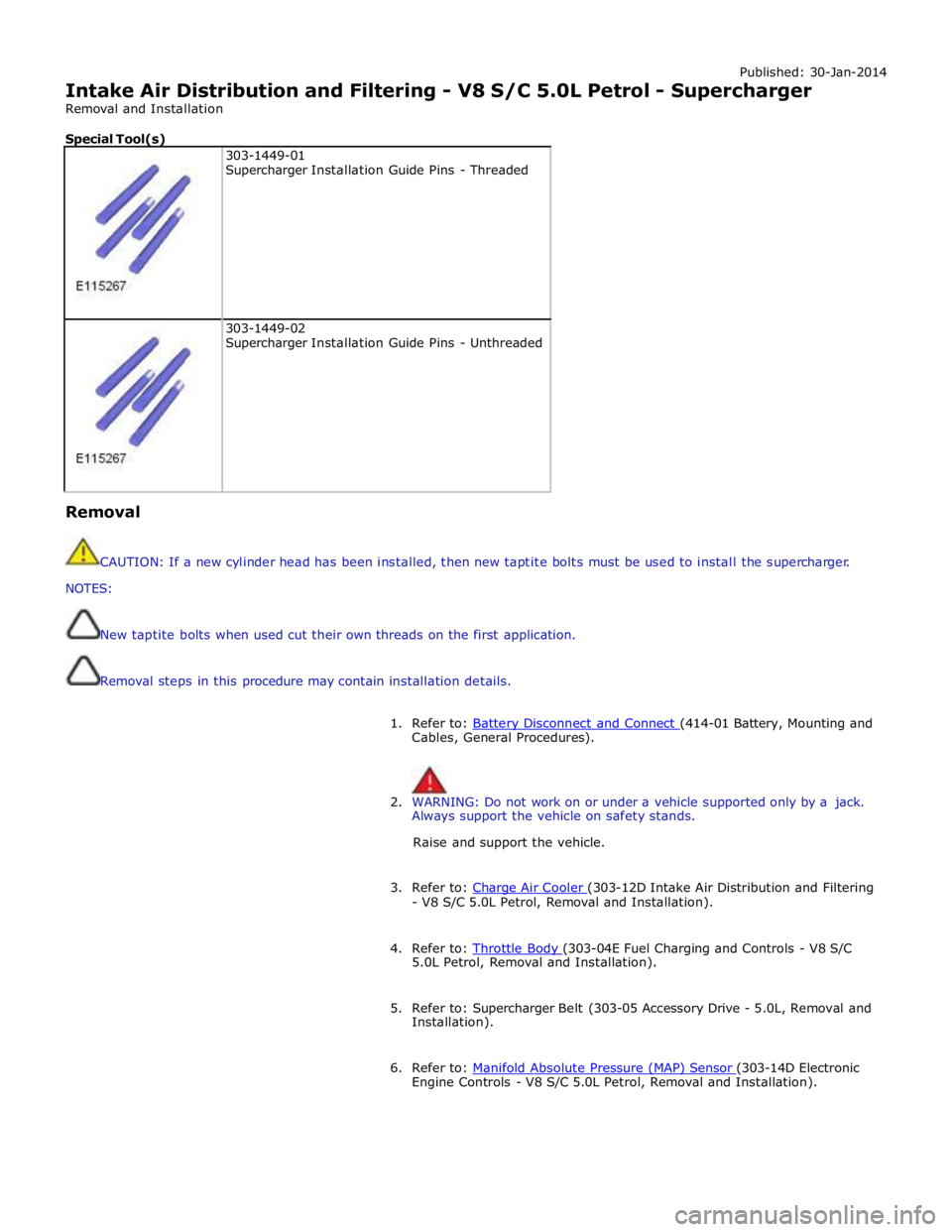
Published: 30-Jan-2014
Intake Air Distribution and Filtering - V8 S/C 5.0L Petrol - Supercharger
Removal and Installation
Special Tool(s)
303-1449-01
Supercharger Installation Guide Pins - Threaded
303-1449-02
Supercharger Installation Guide Pins - Unthreaded Removal
CAUTION: If a new cylinder head has been installed, then new taptite bolts must be used to install the supercharger.
NOTES:
New taptite bolts when used cut their own threads on the first application.
Removal steps in this procedure may contain installation details.
1. Refer to: Battery Disconnect and Connect (414-01 Battery, Mounting and Cables, General Procedures).
2. WARNING: Do not work on or under a vehicle supported only by a jack.
Always support the vehicle on safety stands.
Raise and support the vehicle.
3. Refer to: Charge Air Cooler (303-12D Intake Air Distribution and Filtering - V8 S/C 5.0L Petrol, Removal and Installation).
4. Refer to: Throttle Body (303-04E Fuel Charging and Controls - V8 S/C 5.0L Petrol, Removal and Installation).
5. Refer to: Supercharger Belt (303-05 Accessory Drive - 5.0L, Removal and
Installation).
6. Refer to: Manifold Absolute Pressure (MAP) Sensor (303-14D Electronic Engine Controls - V8 S/C 5.0L Petrol, Removal and Installation).
Page 1344 of 3039
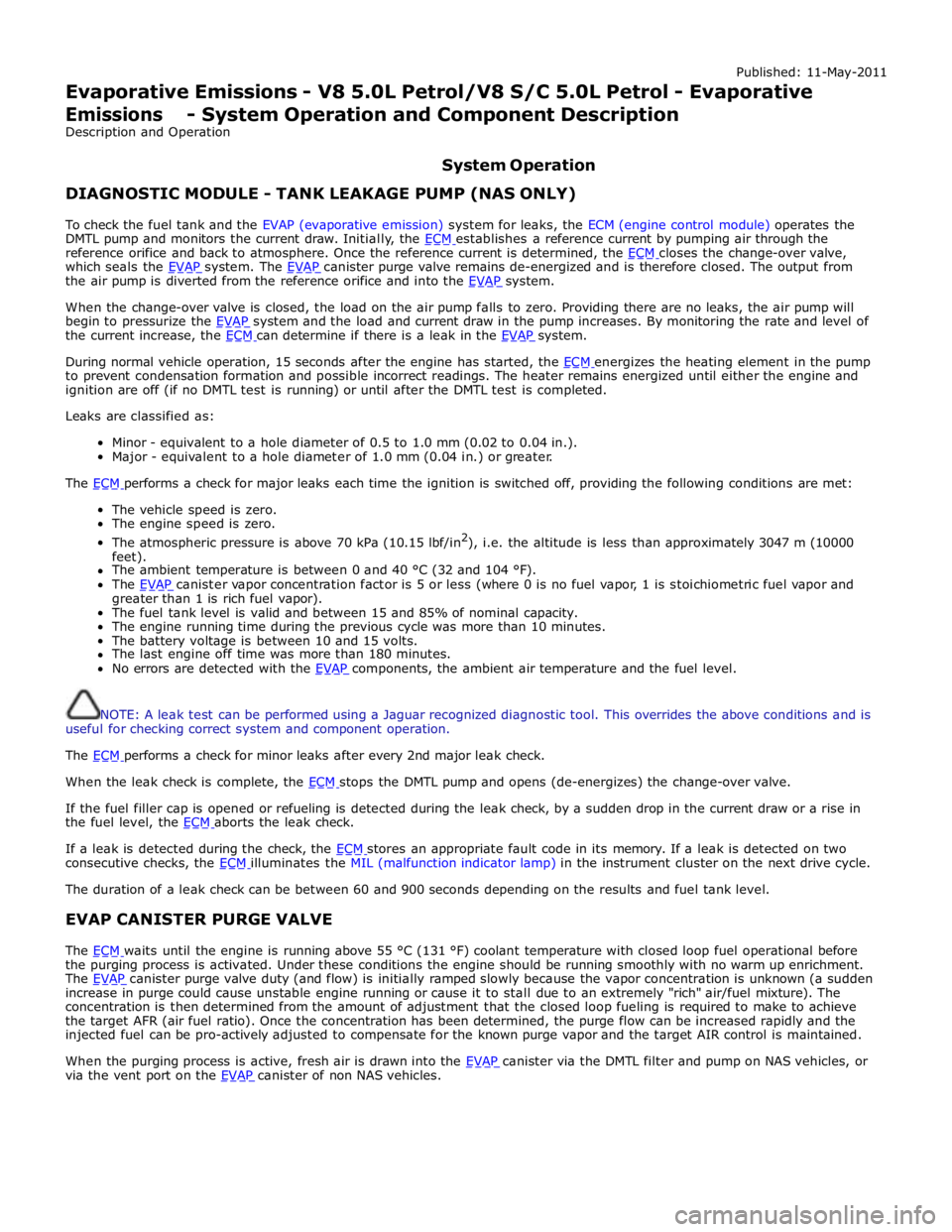
Published: 11-May-2011
Evaporative Emissions - V8 5.0L Petrol/V8 S/C 5.0L Petrol - Evaporative Emissions - System Operation and Component Description
Description and Operation
System Operation DIAGNOSTIC MODULE - TANK LEAKAGE PUMP (NAS ONLY)
To check the fuel tank and the EVAP (evaporative emission) system for leaks, the ECM (engine control module) operates the
DMTL pump and monitors the current draw. Initially, the ECM establishes a reference current by pumping air through the reference orifice and back to atmosphere. Once the reference current is determined, the ECM closes the change-over valve, which seals the EVAP system. The EVAP canister purge valve remains de-energized and is therefore closed. The output from the air pump is diverted from the reference orifice and into the EVAP system.
When the change-over valve is closed, the load on the air pump falls to zero. Providing there are no leaks, the air pump will
begin to pressurize the EVAP system and the load and current draw in the pump increases. By monitoring the rate and level of the current increase, the ECM can determine if there is a leak in the EVAP system.
During normal vehicle operation, 15 seconds after the engine has started, the ECM energizes the heating element in the pump to prevent condensation formation and possible incorrect readings. The heater remains energized until either the engine and
ignition are off (if no DMTL test is running) or until after the DMTL test is completed.
Leaks are classified as:
Minor - equivalent to a hole diameter of 0.5 to 1.0 mm (0.02 to 0.04 in.).
Major - equivalent to a hole diameter of 1.0 mm (0.04 in.) or greater.
The ECM performs a check for major leaks each time the ignition is switched off, providing the following conditions are met: The vehicle speed is zero.
The engine speed is zero.
The atmospheric pressure is above 70 kPa (10.15 lbf/in2
), i.e. the altitude is less than approximately 3047 m (10000
feet).
The ambient temperature is between 0 and 40 °C (32 and 104 °F).
The EVAP canister vapor concentration factor is 5 or less (where 0 is no fuel vapor, 1 is stoichiometric fuel vapor and greater than 1 is rich fuel vapor).
The fuel tank level is valid and between 15 and 85% of nominal capacity.
The engine running time during the previous cycle was more than 10 minutes.
The battery voltage is between 10 and 15 volts.
The last engine off time was more than 180 minutes.
No errors are detected with the EVAP components, the ambient air temperature and the fuel level.
NOTE: A leak test can be performed using a Jaguar recognized diagnostic tool. This overrides the above conditions and is
useful for checking correct system and component operation.
The ECM performs a check for minor leaks after every 2nd major leak check.
When the leak check is complete, the ECM stops the DMTL pump and opens (de-energizes) the change-over valve.
If the fuel filler cap is opened or refueling is detected during the leak check, by a sudden drop in the current draw or a rise in
the fuel level, the ECM aborts the leak check.
If a leak is detected during the check, the ECM stores an appropriate fault code in its memory. If a leak is detected on two consecutive checks, the ECM illuminates the MIL (malfunction indicator lamp) in the instrument cluster on the next drive cycle. The duration of a leak check can be between 60 and 900 seconds depending on the results and fuel tank level.
EVAP CANISTER PURGE VALVE
The ECM waits until the engine is running above 55 °C (131 °F) coolant temperature with closed loop fuel operational before the purging process is activated. Under these conditions the engine should be running smoothly with no warm up enrichment.
The EVAP canister purge valve duty (and flow) is initially ramped slowly because the vapor concentration is unknown (a sudden increase in purge could cause unstable engine running or cause it to stall due to an extremely "rich" air/fuel mixture). The
concentration is then determined from the amount of adjustment that the closed loop fueling is required to make to achieve
the target AFR (air fuel ratio). Once the concentration has been determined, the purge flow can be increased rapidly and the
injected fuel can be pro-actively adjusted to compensate for the known purge vapor and the target AIR control is maintained.
When the purging process is active, fresh air is drawn into the EVAP canister via the DMTL filter and pump on NAS vehicles, or via the vent port on the EVAP canister of non NAS vehicles.
Page 1348 of 3039
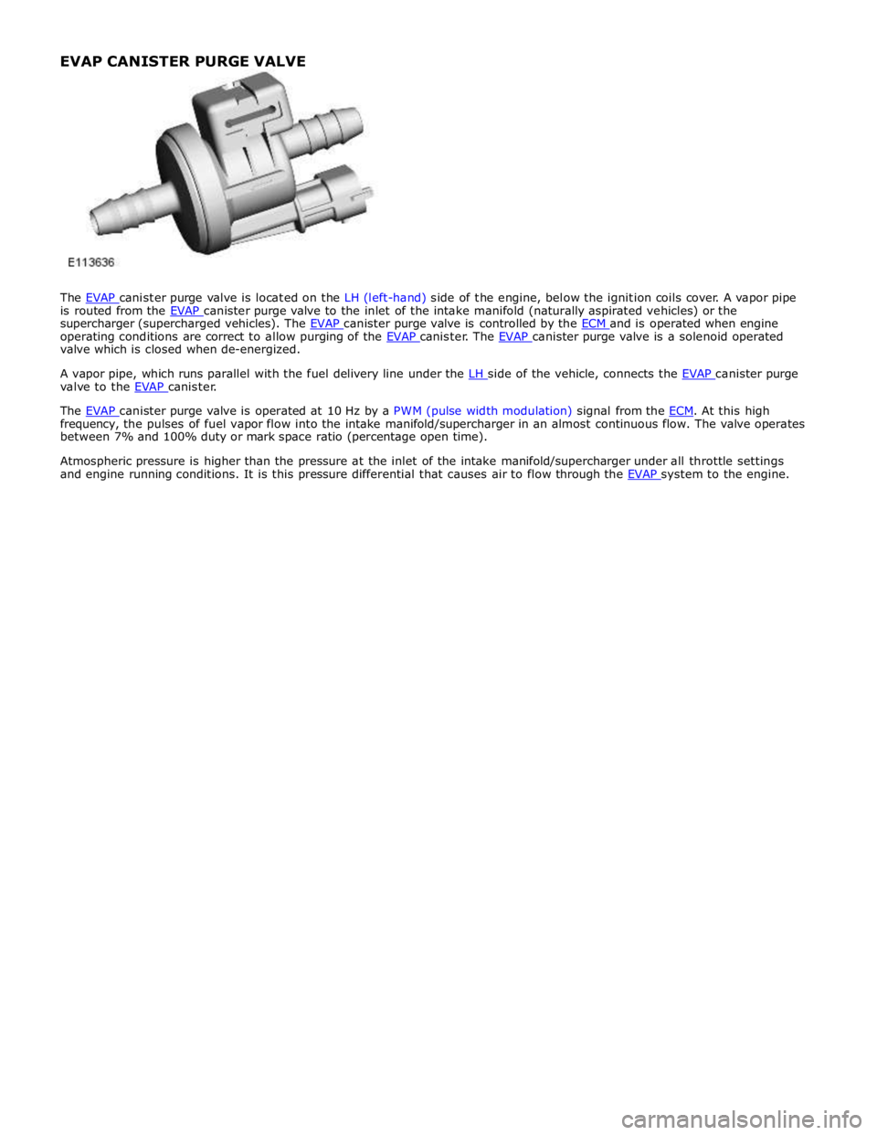
is routed from the EVAP canister purge valve to the inlet of the intake manifold (naturally aspirated vehicles) or the supercharger (supercharged vehicles). The EVAP canister purge valve is controlled by the ECM and is operated when engine operating conditions are correct to allow purging of the EVAP canister. The EVAP canister purge valve is a solenoid operated valve which is closed when de-energized.
A vapor pipe, which runs parallel with the fuel delivery line under the LH side of the vehicle, connects the EVAP canister purge valve to the EVAP canister.
The EVAP canister purge valve is operated at 10 Hz by a PWM (pulse width modulation) signal from the ECM. At this high frequency, the pulses of fuel vapor flow into the intake manifold/supercharger in an almost continuous flow. The valve operates
between 7% and 100% duty or mark space ratio (percentage open time).
Atmospheric pressure is higher than the pressure at the inlet of the intake manifold/supercharger under all throttle settings
and engine running conditions. It is this pressure differential that causes air to flow through the EVAP system to the engine. EVAP CANISTER PURGE VALVE
Page 1353 of 3039
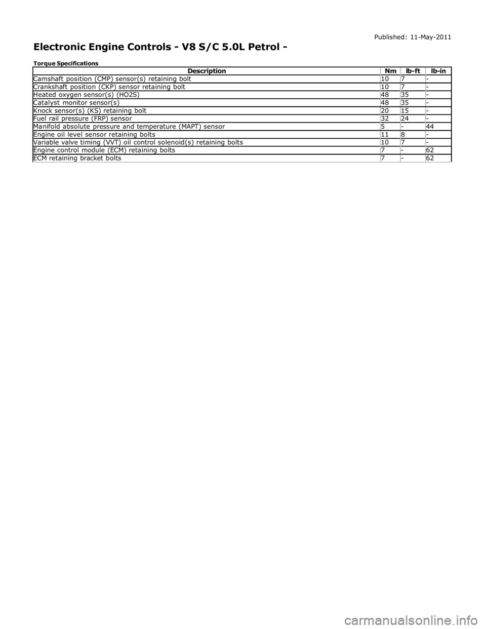
Camshaft position (CMP) sensor(s) retaining bolt 10 7 - Crankshaft position (CKP) sensor retaining bolt 10 7 - Heated oxygen sensor(s) (HO2S) 48 35 - Catalyst monitor sensor(s) 48 35 - Knock sensor(s) (KS) retaining bolt 20 15 - Fuel rail pressure (FRP) sensor 32 24 - Manifold absolute pressure and temperature (MAPT) sensor 5 - 44 Engine oil level sensor retaining bolts 11 8 - Variable valve timing (VVT) oil control solenoid(s) retaining bolts 10 7 - Engine control module (ECM) retaining bolts 7 - 62 ECM retaining bracket bolts 7 - 62
Page 1360 of 3039
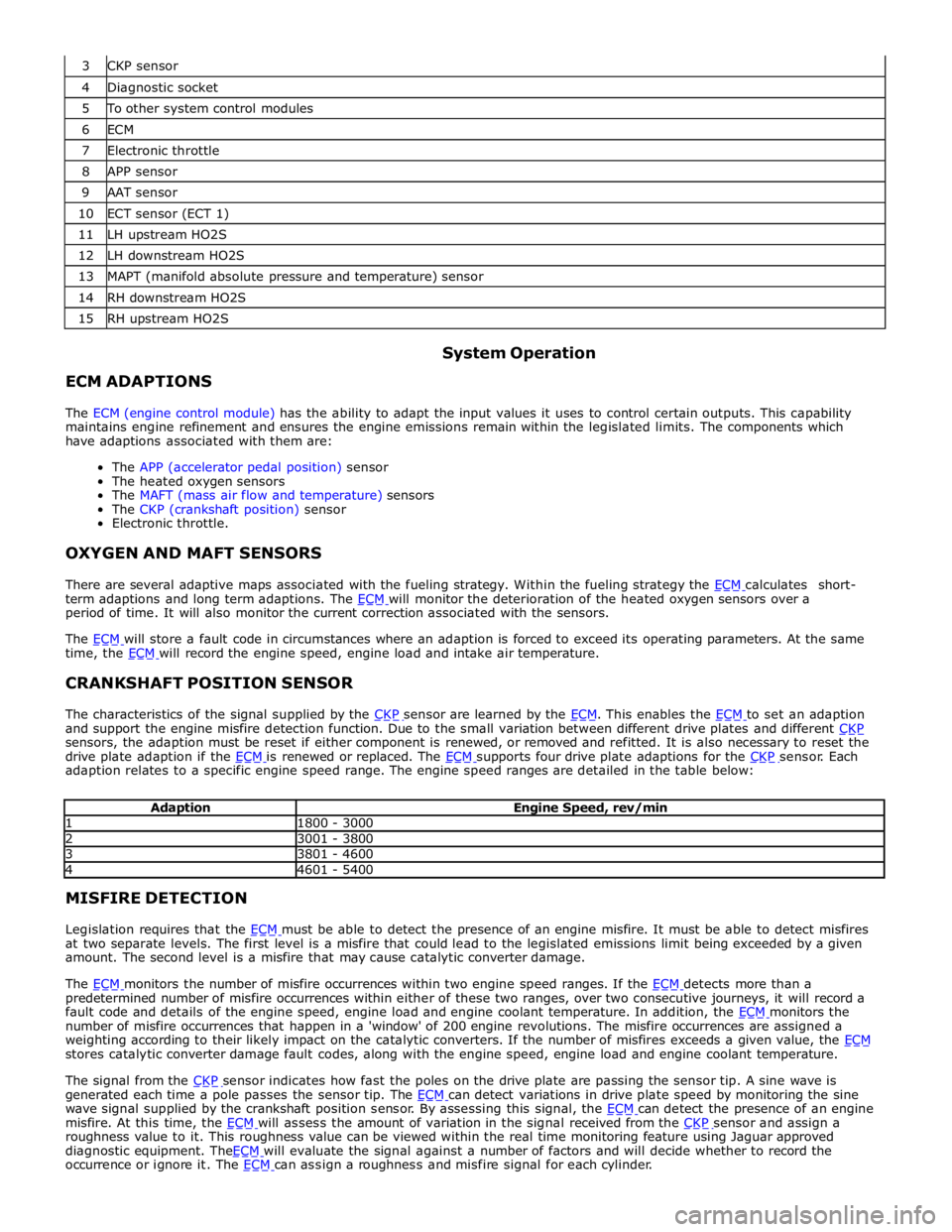
4 Diagnostic socket 5 To other system control modules 6 ECM 7 Electronic throttle 8 APP sensor 9 AAT sensor 10 ECT sensor (ECT 1) 11 LH upstream HO2S 12 LH downstream HO2S 13 MAPT (manifold absolute pressure and temperature) sensor 14 RH downstream HO2S 15 RH upstream HO2S
ECM ADAPTIONS System Operation
The ECM (engine control module) has the ability to adapt the input values it uses to control certain outputs. This capability
maintains engine refinement and ensures the engine emissions remain within the legislated limits. The components which
have adaptions associated with them are:
The APP (accelerator pedal position) sensor
The heated oxygen sensors
The MAFT (mass air flow and temperature) sensors
The CKP (crankshaft position) sensor
Electronic throttle.
OXYGEN AND MAFT SENSORS
There are several adaptive maps associated with the fueling strategy. Within the fueling strategy the ECM calculates short-term adaptions and long term adaptions. The ECM will monitor the deterioration of the heated oxygen sensors over a period of time. It will also monitor the current correction associated with the sensors.
The ECM will store a fault code in circumstances where an adaption is forced to exceed its operating parameters. At the same time, the ECM will record the engine speed, engine load and intake air temperature.
CRANKSHAFT POSITION SENSOR
The characteristics of the signal supplied by the CKP sensor are learned by the ECM. This enables the ECM to set an adaption and support the engine misfire detection function. Due to the small variation between different drive plates and different CKP sensors, the adaption must be reset if either component is renewed, or removed and refitted. It is also necessary to reset the
drive plate adaption if the ECM is renewed or replaced. The ECM supports four drive plate adaptions for the CKP sensor. Each adaption relates to a specific engine speed range. The engine speed ranges are detailed in the table below:
Adaption Engine Speed, rev/min 1 1800 - 3000 2 3001 - 3800 3 3801 - 4600 4 4601 - 5400 MISFIRE DETECTION
Legislation requires that the ECM must be able to detect the presence of an engine misfire. It must be able to detect misfires at two separate levels. The first level is a misfire that could lead to the legislated emissions limit being exceeded by a given
amount. The second level is a misfire that may cause catalytic converter damage.
The ECM monitors the number of misfire occurrences within two engine speed ranges. If the ECM detects more than a predetermined number of misfire occurrences within either of these two ranges, over two consecutive journeys, it will record a
fault code and details of the engine speed, engine load and engine coolant temperature. In addition, the ECM monitors the number of misfire occurrences that happen in a 'window' of 200 engine revolutions. The misfire occurrences are assigned a
weighting according to their likely impact on the catalytic converters. If the number of misfires exceeds a given value, the ECM stores catalytic converter damage fault codes, along with the engine speed, engine load and engine coolant temperature.
The signal from the CKP sensor indicates how fast the poles on the drive plate are passing the sensor tip. A sine wave is generated each time a pole passes the sensor tip. The ECM can detect variations in drive plate speed by monitoring the sine wave signal supplied by the crankshaft position sensor. By assessing this signal, the ECM can detect the presence of an engine misfire. At this time, the ECM will assess the amount of variation in the signal received from the CKP sensor and assign a roughness value to it. This roughness value can be viewed within the real time monitoring feature using Jaguar approved
diagnostic equipment. TheECM will evaluate the signal against a number of factors and will decide whether to record the occurrence or ignore it. The ECM can assign a roughness and misfire signal for each cylinder.