Engine JAGUAR XFR 2010 1.G Workshop Manual
[x] Cancel search | Manufacturer: JAGUAR, Model Year: 2010, Model line: XFR, Model: JAGUAR XFR 2010 1.GPages: 3039, PDF Size: 58.49 MB
Page 2797 of 3039
(100-00 General Information, Description and Operation) /
Body Repairs (501-25A Body Repairs - General Information, Description and Operation) /
Corrosion Protection (501-25B Body Repairs - Corrosion Protection, Description and Operation) /
Body and Frame (501-26 Body Repairs - Vehicle Specific Information and Tolerance Checks, Description and Operation).
5. Remove the fender apron panel front extension.
For additional information, refer to: Fender Apron Panel Front Extension (501-27 Front End Sheet Metal Repairs, Removal and Installation).
6. Remove the front fender support bracket.
For additional information, refer to: Front Fender Support Bracket (501-27 Front End Sheet Metal Repairs, Removal and Installation).
7. Remove the fender apron panel.
For additional information, refer to: Fender Apron Panel (501-27 Front End Sheet Metal Repairs, Removal and Installation).
8. Remove the engine, transmission / transaxle, front subframe and front
suspension, as an assembly.
For additional information, refer to: Engine (303-01A, Removal) /
Engine (303-01B Engine - V6 3.0L Petrol, Removal) / Engine (303-01D, Removal) /
Engine (303-01E, Removal) /
Transmission - 2.7L Diesel (307-01, Removal) /
Transmission - TDV6 3.0L Diesel (307-01B Automatic Transmission/Transaxle - TDV6 3.0L Diesel /V8 5.0L Petrol/V8 S/C 5.0L
Petrol, Removal) /
Transmission (307-01A Automatic Transmission/Transaxle - V6 3.0L Petrol, Removal) /
Transmission - 4.2L (307-01, Removal) /
Transmission - V8 5.0L Petrol/V8 S/C 5.0L Petrol (307-01B Automatic Transmission/Transaxle - TDV6 3.0L Diesel /V8 5.0L Petrol/V8 S/C 5.0L
Petrol, Removal) /
Front Shock Absorber (204-01 Front Suspension, Removal and Installation) /
Front Subframe - 2.7L Diesel (502-00, Removal and Installation) /
Front Subframe - V6 3.0L Petrol (502-00 Uni-Body, Subframe and Mounting System, Removal and Installation) /
Front Subframe - 4.2L, Vehicles Without: Supercharger (502-00, Removal
and Installation) /
Front Subframe - 4.2L, Vehicles With: Supercharger (502-00, Removal
and Installation).
9. Remove the pedestrian protection hood actuator.
For additional information, refer to: Pedestrian Protection Hood Actuator LH (501-20C Pedestrian Protection System, Removal and Installation) / Pedestrian Protection Hood Actuator RH (501-20C Pedestrian Protection System, Removal and Installation).
10. If the drivers side front side member and suspension top mount is to be
repaired, remove the brake master cylinder and reservoir.
For additional information, refer to: Brake Master Cylinder (206-06 Hydraulic Brake Actuation, Removal and Installation) /
Brake Fluid Reservoir (206-06 Hydraulic Brake Actuation, Removal and Installation).
11. If the drivers side front side member and suspension top mount is to be
repaired, remove the brake booster.
Page 2798 of 3039

Actuation, Removal and Installation).
12. Remove the left-hand and right-hand front seats.
For additional information, refer to: Front Seat (501-10 Seating, Removal and Installation).
13. Remove the heater core and evaporator core housing.
For additional information, refer to: Heater Core and Evaporator Core Housing (412-01 Climate Control, Removal and Installation).
14. Remove the front safety belt retractor.
For additional information, refer to: Front Safety Belt Retractor (501-20A Safety Belt System, Removal and Installation).
15. Remove the B-pillar side impact sensor.
For additional information, refer to: B-Pillar Side Impact Sensor (501-20B Supplemental Restraint System, Removal and Installation).
16. Remove the left-hand and right-hand front floor covering.
17. Remove the rear floor covering.
18. If the left-hand front side member and suspension top mount assembly
is to be repaired, remove the left-hand rear foot well duct.
19. If the right-hand front side member and suspension top mount assembly
is to be repaired, remove the right-hand rear foot well duct.
20. If the drivers side front side member and suspension top mount is being
repaired, remove the pedal box.
21. Release and position the insulating material at the inner bulkhead to
one side.
22. Release and position the inner bulkhead and floor panel wiring harness
to one side.
23. Drain the fuel tank.
For additional information, refer to: Fuel Tank Draining (310-00 Fuel System - General Information, General Procedures).
24. If the left-hand front side member and suspension top mount assembly
is to be repaired, remove the left-hand under shield.
25. If the right-hand front side member and suspension top mount assembly
is to be repaired, remove the right-hand under shield.
26. If the left-hand front side member and suspension top mount assembly
is to be repaired, remove the fuel supply and return pipes.
27. For diesel engine vehicles only, if the left-hand front side member and
suspension top mount assembly is to be repaired, remove the fuel
cooler.
28. If the right-hand front side member and suspension top mount assembly
is to be repaired, release and position the underfloor wiring harness to
Page 2801 of 3039

37.
38.
39. Drill out the spot welds as indicated.
Drill out the spot welds as indicated.
NOTE: The spot welds indicated should be drilled from
inside the engine compartment, to allow spot welding on
installation.
Drill out the spot welds as indicated.
Page 2807 of 3039
Published: 11-May-2011
Front End Sheet Metal Repairs - Front Side Member Closing Panel
Removal and Installation
Removal
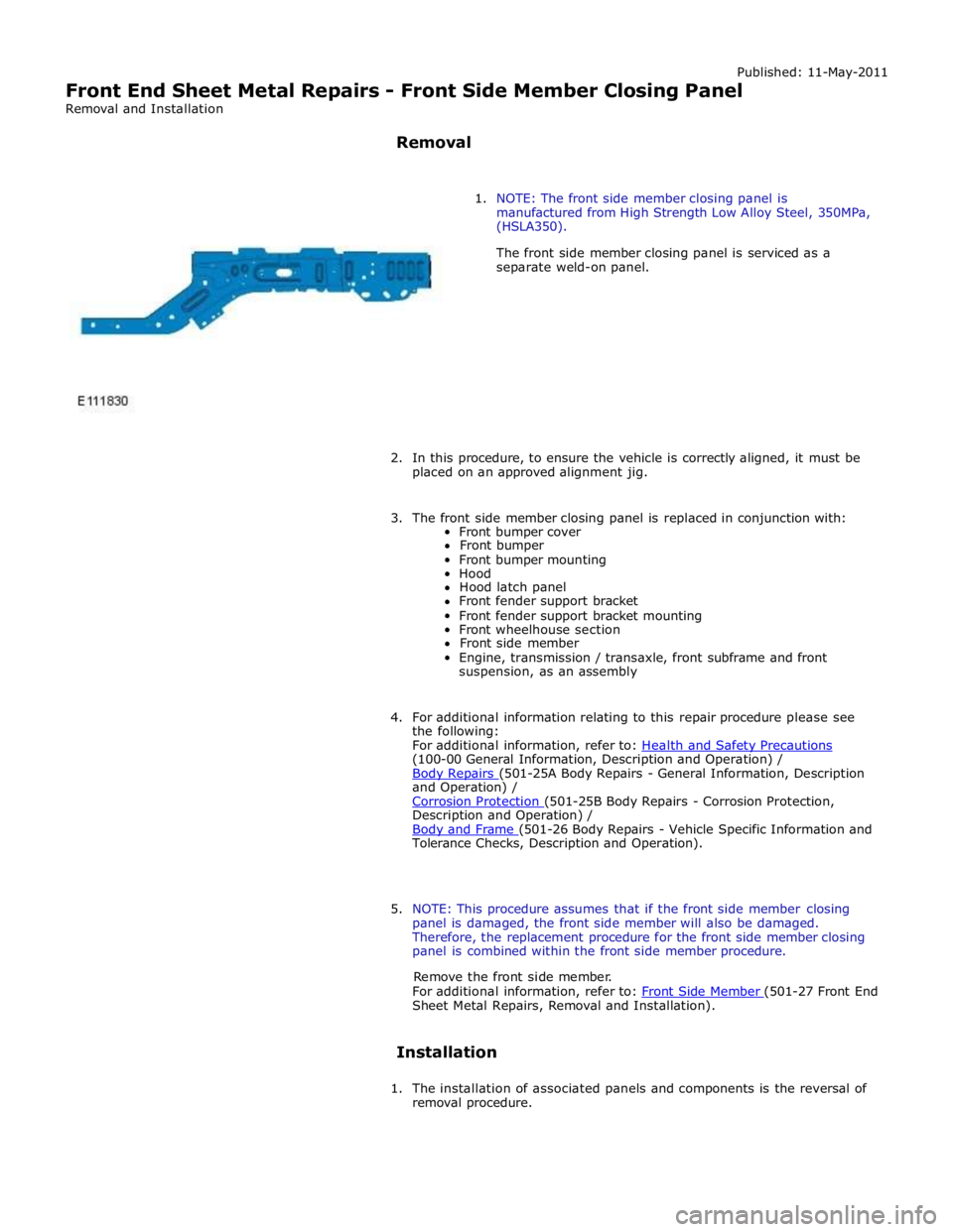
1. NOTE: The front side member closing panel is
manufactured from High Strength Low Alloy Steel, 350MPa,
(HSLA350).
The front side member closing panel is serviced as a
separate weld-on panel.
2. In this procedure, to ensure the vehicle is correctly aligned, it must be
placed on an approved alignment jig.
3. The front side member closing panel is replaced in conjunction with:
Front bumper cover
Front bumper
Front bumper mounting
Hood
Hood latch panel
Front fender support bracket
Front fender support bracket mounting
Front wheelhouse section
Front side member
Engine, transmission / transaxle, front subframe and front
suspension, as an assembly
4. For additional information relating to this repair procedure please see
the following:
For additional information, refer to: Health and Safety Precautions (100-00 General Information, Description and Operation) /
Body Repairs (501-25A Body Repairs - General Information, Description and Operation) /
Corrosion Protection (501-25B Body Repairs - Corrosion Protection, Description and Operation) /
Body and Frame (501-26 Body Repairs - Vehicle Specific Information and Tolerance Checks, Description and Operation).
5. NOTE: This procedure assumes that if the front side member closing
panel is damaged, the front side member will also be damaged.
Therefore, the replacement procedure for the front side member closing
panel is combined within the front side member procedure.
Remove the front side member.
For additional information, refer to: Front Side Member (501-27 Front End Sheet Metal Repairs, Removal and Installation).
Installation
1. The installation of associated panels and components is the reversal of
removal procedure.
Page 2821 of 3039
Lighting, Removal and Installation).
7. Remove the condenser core.
For additional information, refer to: Condenser Core - 2.7L Diesel
(412-03, Removal and Installation) /
Condenser Core - V6 3.0L Petrol (412-03 Air Conditioning, Removal and Installation) /
Condenser Core - 4.2L, Vehicles Without: Supercharger (412-03, Removal
and Installation) /
Condenser Core - 4.2L, Vehicles With: Supercharger (412-03, Removal
and Installation).
8. Remove the radiator.
For additional information, refer to: Radiator (303-03A, Removal and
Installation) /
Radiator (303-03B Engine Cooling - V6 3.0L Petrol, Removal and Installation) /
Radiator - Vehicles With: Supercharger (303-03C, Removal and
Installation) /
Radiator - Vehicles Without: Supercharger (303-03C, Removal and
Installation).
9. Remove the both hood latch panel braces.
10. Remove the cooling fan upper shroud.
11. Remove both crash sensors.
For additional information, refer to: Crash Sensor (501-20B Supplemental Restraint System, Removal and Installation).
12. Remove the both hood latches.
13. Remove the hood safety hook guide.
14. Remove both hood latch panel buffers.
15. Release and lay aside the hood latch panel wiring harness.
16. Remove the old panel.
Page 2982 of 3039

12.
13.
14.
15. NOTE: A new striker reinforcement panel is supplied
on the quarter panel service panel.
Separate the joints, the adhesive and the NVH (noise,
vibration and harshness) component and remove the striker
reinforcement panel.
NOTE: Care should be taken when separating and
removing the ECM (engine control module) mounting
bracket if it is to be reused.
If the right-hand rear wheelhouse outer is to be repaired,
drill out the spot welds as indicated and remove the ECM
mounting bracket. Retain for reuse on installation.
NOTE: It is necessary to section the quarter panel
inner reinforcement at the point indicated, to make sure the
integrity of the safety belt anchorage point. The right-hand
panel is illustrated, the left-hand is similar.
Cut the quarter panel inner reinforcement, horizontally,
approximately 90mm from the centre of the safety belt bolt
anchorage point as indicated.
NOTE: The right-hand panel is illustrated, the
left-hand is similar although there are additional spot welds
to drill out.
Drill out the spot welds from the quarter panel inner
reinforcement section at the points indicated.
Page 3013 of 3039

Front lower arm to front subframe retaining nut and bolt 175 129 - Rear lower arm to front subframe retaining nut and bolt 175 129 - Engine mount lower retaining nut 63 46 - Steering gear retaining bolts 100 74 - Front Shock absorber and spring assembly retaining bolt 175 129 - Front subframe to body front retaining bolt Stage 1 100 73 - Stage 2 270° 270° - Front subframe to body rear retaining bolt Stage 1 80 59 - Stage 2 240° 240° - Front Stabilizer bar link retaining nuts 43 31 - Front Stabilizer bar link retaining bolts 55 41 - Rear Shock absorber and spring assembly retaining bolt 133 98 - Rear subframe reinforcement plate retaining bolts 47 35 - Rear subframe to body retaining bolts Stage 1 80 59 - Stage 2 240° 240° -
Page 3014 of 3039
Published: 31-Jul-2013
Uni-Body, Subframe and Mounting System - Front Subframe V8 5.0L Petrol/V8 S/C 5.0L Petrol
Removal and Installation
Special Tool(s)
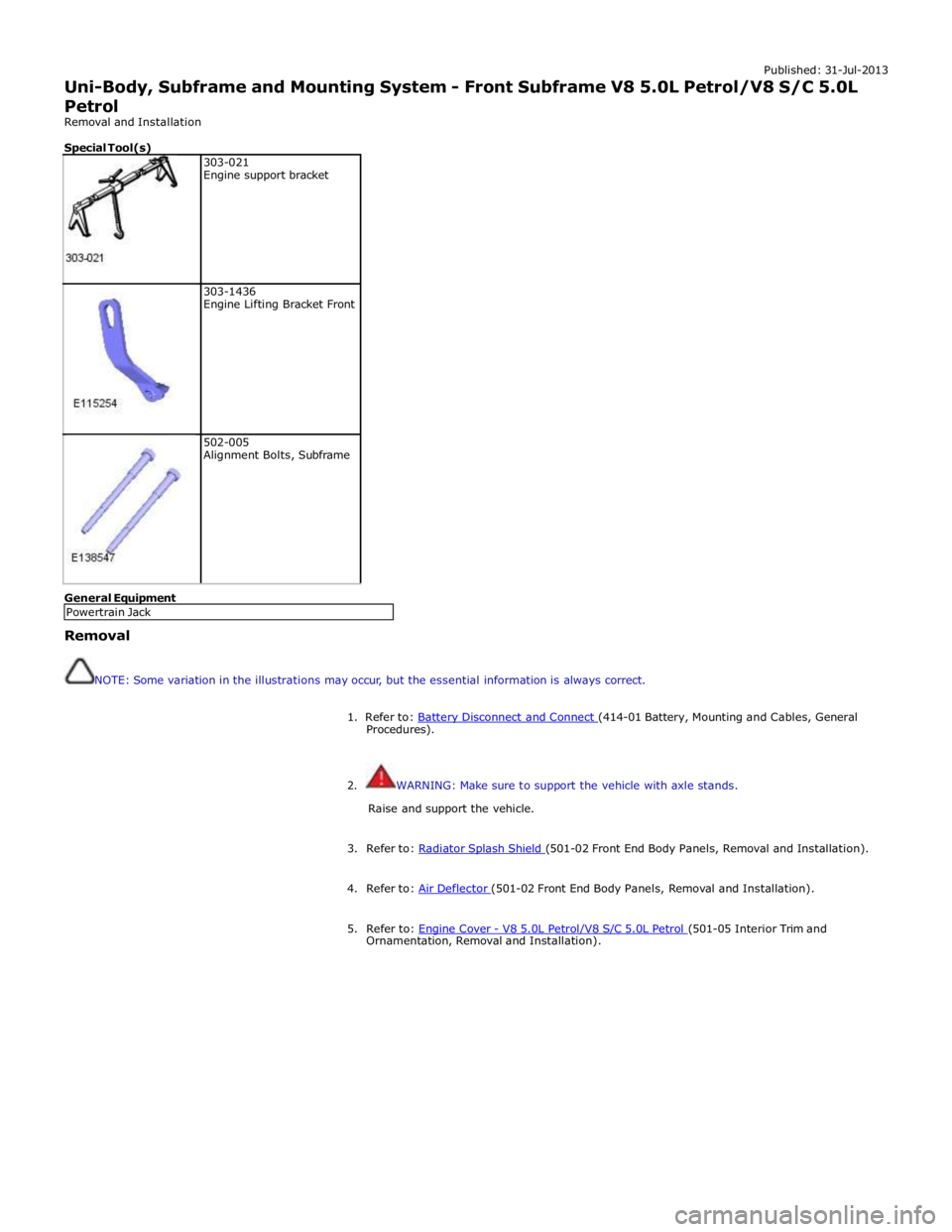
303-021
Engine support bracket
303-1436
Engine Lifting Bracket Front
502-005
Alignment Bolts, Subframe General Equipment
Removal
NOTE: Some variation in the illustrations may occur, but the essential information is always correct.
1. Refer to: Battery Disconnect and Connect (414-01 Battery, Mounting and Cables, General Procedures).
2. WARNING: Make sure to support the vehicle with axle stands.
Raise and support the vehicle.
3. Refer to: Radiator Splash Shield (501-02 Front End Body Panels, Removal and Installation). 4. Refer to: Air Deflector (501-02 Front End Body Panels, Removal and Installation). 5. Refer to: Engine Cover - V8 5.0L Petrol/V8 S/C 5.0L Petrol (501-05 Interior Trim and Ornamentation, Removal and Installation). Powertrain Jack
Page 3015 of 3039
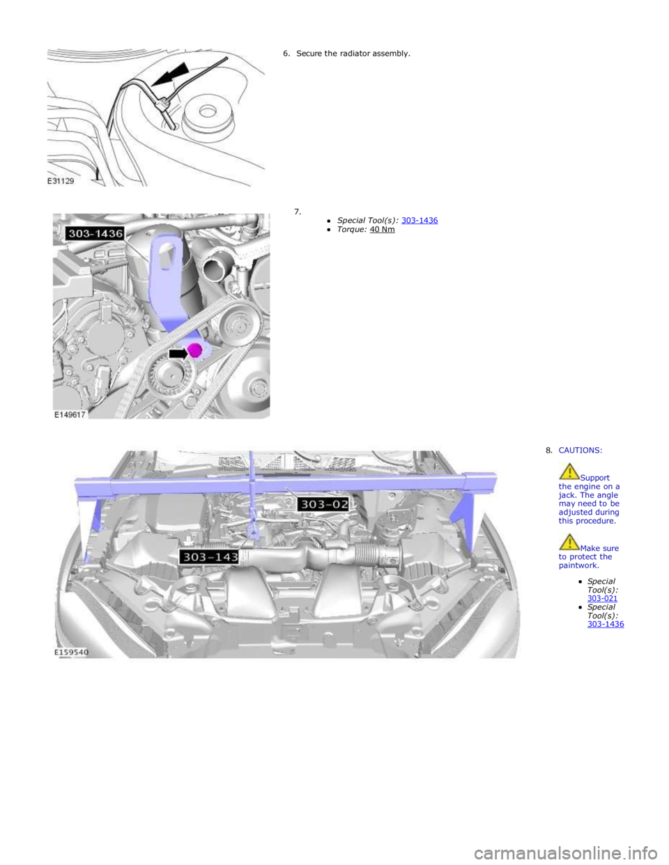
6. Secure the radiator assembly.
7.
Special Tool(s): 303-1436 Torque: 40 Nm
8. CAUTIONS:
Support the engine on a jack. The angle may need to be adjusted during this procedure.
Make sure to protect the paintwork.
Special Tool(s): 303-021 Special Tool(s): 303-1436
Page 3031 of 3039
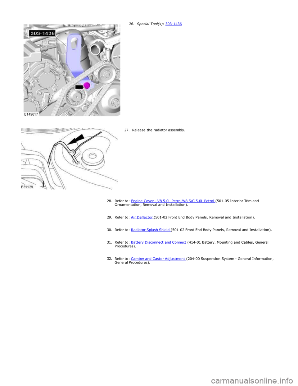
27. Release the radiator assembly.
28.
Refer to: Engine Cover - V8 5.0L Petrol/V8 S/C 5.0L Petrol (501-05 Interior Trim and Ornamentation, Removal and Installation).
29. Refer to: Air Deflector (501-02 Front End Body Panels, Removal and Installation). 30. Refer to: Radiator Splash Shield (501-02 Front End Body Panels, Removal and Installation). 31. Refer to: Battery Disconnect and Connect (414-01 Battery, Mounting and Cables, General Procedures).
32.
Refer to: Camber and Caster Adjustment (204-00 Suspension System - General Information, General Procedures).