ECO mode JAGUAR XFR 2010 1.G Repair Manual
[x] Cancel search | Manufacturer: JAGUAR, Model Year: 2010, Model line: XFR, Model: JAGUAR XFR 2010 1.GPages: 3039, PDF Size: 58.49 MB
Page 1882 of 3039

11 Secondary battery 12 Dual Battery Junction Box (DBJB) 13 Rear Junction Box (RJB) 14 Megafuse 15 Battery Junction box (BJB) 16 Primary battery
System Operation BATTERY MONITORING SYSTEM - TD4 2.2L DIESEL VEHICLES ONLY
Periodically the battery monitoring system module will instigate a self-calibration routine. To self calibrate, the battery
monitoring system first charges the battery to its full condition.
NOTE: If the vehicle is only driven for short periods the charging process could take a number of days to complete.
Once the battery is fully charged, the battery monitoring system will discharge the battery to approximately 75% of its full
state of charge, but never lower than 12.2 V. The time taken to complete this part of the routine is dependent on the electrical
load on the vehicle.
When the second part of the routine has been successfully completed, the battery monitoring system will return the battery to
its optimum level of charge. The optimum level of charge will be between 12.6 V and 15 V, depending on battery condition,
temperature and loading.
The battery monitoring system module also monitors the battery condition with the engine switched off. If a low voltage
condition is detected the module can request the infotainment system is switched off to protect battery voltage. Once the
infotainment system has been switched off, the vehicle must be run for at least 5 minutes to charge the battery before the
infotainment system can be operated with the engine switched off.
BATTERY MONITORING SYSTEM - SINGLE AND DUAL BATTERY SYSTEM VEHICLES
When the ignition is off (power mode 0), the BMS control module records the primary battery state of charge and begins to
monitor the battery condition from this point.
If the battery state of charge falls by 7%, the BMS control module will monitor the primary battery for 5 minutes. If after the 5
minute monitoring period, the primary battery charge has continued to fall due to the quiescent drain current being too high,
the BMS control module will determine that some control modules are still 'awake'. The BMS control module sends a shutdown
message on the LIN (local interconnect network) bus to the GWM (Gateway Module). The GWM sends a CAN (controller area
network) bus message on both the medium and high speed networks to all control modules, requesting them to shutdown.
The BMS control module will monitor the primary battery state of charge for a further 5 minutes and determine if the primary
battery state of charge is still dropping. If a quiescent drain current continues, the primary battery state of charge will
continue to drop. If the state of charge falls to 12% of the initial monitoring value, the BMS control module determines that
one or more control modules are still awake and a failure to respond to the shutdown request may indicate an error state
within the control module(s).
BMS Low Battery Warning and Energy Management Messages
The BMS continuously monitors the condition of the primary vehicle battery. If excessive battery discharge occurs, the system
will begin to shut down non-essential electrical systems in order to protect the battery.
If the BMS calculates that battery condition is not within set parameters, there are 3 messages that can be displayed, 2 on the
touch screen and 1 on the message center. These inform the user that the battery is either at a low level of charge or the
engine-off power consumption limit has been exceeded.
Low Battery - Please switch engine on or system will shutdown in 3 minutes: is displayed as a Warning on the
touch screen if the engine is not running. This indicates that the battery has fallen below a predefined threshold. As
soon as the battery is charged back above this threshold then the message will be removed.
Low Battery - Please start your engine is displayed on the message center if the engine is not running. This indicates
that the battery has fallen below a predefined threshold. As soon as the battery is charged back above this threshold
then the message will be removed or it can be manually removed by pressing 'OK'.
System will shut down in 3 minutes: is displayed as an Energy management on the touch screen if the engine is not
running, and system features are causing excessive battery discharge. After 3 minutes the BMS will begin shutting
down vehicle systems. Normal system operation will resume when the engine is started.
This is based on a percentage of battery capacity available for the customer to use with the engine off. The percentage can
change based upon several factors.
Once triggered, the resetting of this message will not occur until the vehicle is driven for 10 minutes with the engine running
(to allow the battery to recoup any lost charge). However, if the engine is run for less than 10 minutes, the message will only
be displayed after an additional 5 minutes with the ignition on but engine off.
BMS Control Module Self Calibration
Periodically the BMS control module will instigate a self-calibration routine. To self calibrate, the battery monitoring system www.JagDocs.com
Page 1949 of 3039
systems.
A typical example of information transfer is vehicle speed information from the ABS (anti-lock brake system) module used to
control the automatic volume control function. The vehicle speed information from the ABS module is sent on the high speed
CAN network and collected by the instrument panel gateway. The signal is passed to the medium speed CAN network and onto the ICM gateway. The ICM calculates the volume adjustment required. The corrected audio volume level signal is sent on the
MOST network to the IAM or Power amplifier (dependant on vehicle equipment level) for output to the speaker system.
AUDIO SYSTEM USER CONTROLS
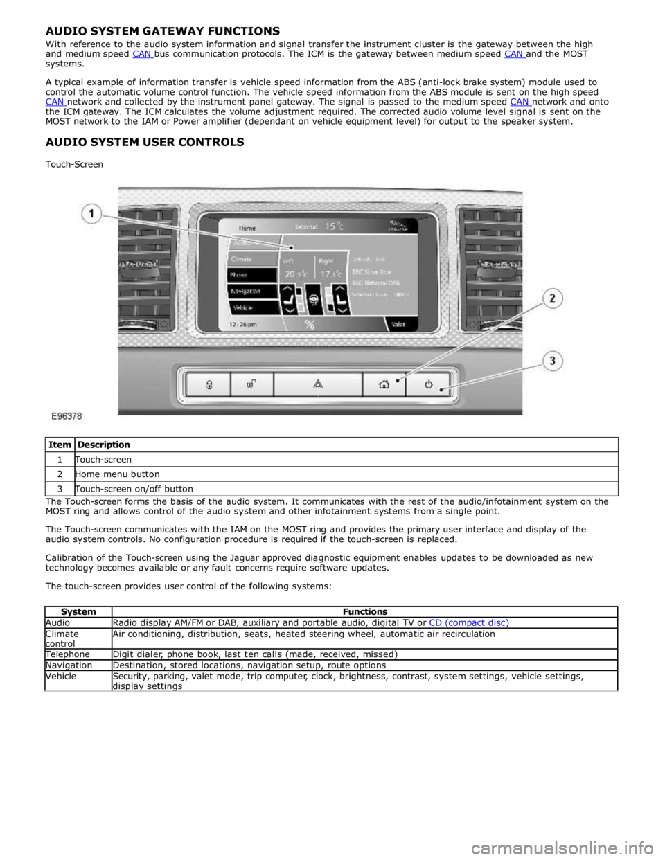
Touch-Screen
Item Description 1 Touch-screen 2 Home menu button 3 Touch-screen on/off button The Touch-screen forms the basis of the audio system. It communicates with the rest of the audio/infotainment system on the
MOST ring and allows control of the audio system and other infotainment systems from a single point.
The Touch-screen communicates with the IAM on the MOST ring and provides the primary user interface and display of the
audio system controls. No configuration procedure is required if the touch-screen is replaced.
Calibration of the Touch-screen using the Jaguar approved diagnostic equipment enables updates to be downloaded as new
technology becomes available or any fault concerns require software updates.
The touch-screen provides user control of the following systems:
System Functions Audio Radio display AM/FM or DAB, auxiliary and portable audio, digital TV or CD (compact disc) Climate
control Air conditioning, distribution, seats, heated steering wheel, automatic air recirculation Telephone Digit dialer, phone book, last ten calls (made, received, missed) Navigation Destination, stored locations, navigation setup, route options Vehicle
Security, parking, valet mode, trip computer, clock, brightness, contrast, system settings, vehicle settings, display settings
Page 1966 of 3039

Publi s hed: 11-May-2011
Information and Entertainment System - Cellular Phone - Overview
Des cript ion and Operat ion
Authori ng Templat e
OVERVIEW
The cel lul ar phone s yst em us es t he cus t omers own Bluetooth® capabl e hands et in conjuncti on wit h t he vehicle
informat ion and ent ertai nment sys tem. The t elephone cont rol module i s l ocated under t he left -hand front s eat, and has a
Bluet oot h® ant enna integrat ed i nt o t he unit . Tel ephone handset s mus t be paired wit h t he t el ephone control modul e,
requiring i nput of a PIN (pers onal i dent ificati on number) before t hey can be us ed wi th the vehicle sys tem. Once pai red, any
phone can be docked to the car wi thout re-ent eri ng a PIN (pers onal identi fi cat ion number). In addit ion t o t hi s , the l ast
connected device wi ll dock aut omati cal ly t he next ti me i t is pl aced i n t he vehi cl e a nd t he ignit ion i s i n power mode
(ignit ion on).
The s ys t em has t he abil it y to pai r and dock t elephone hands ets from t he tel ephones t hems elves . By s uppl yi ng a fixed PIN
(personal identi fi cat ion number), a us er wil l be abl e t o us e t hei r tel ephone or othe r t el ephone related Bluetooth® device
and pair wi th i t wit hout us i ng the touch s creen. This enables devices s uch as Blackberry's and ot her s ecure PDA's (pers onal
digit al ass i st ants ) t o pair and dock wit h t he vehi cl e s ys t em.
Up t o 5 telephone hands ets can be pai red wi th the vehicle, but only 1 tel ephone can be us ed at a t ime. The Touch-screen
dis plays phone functi onali ty, i ncl udi ng diali ng, and (if compati ble) t he hands et’s phone book. The Touch-s creen als o
dis plays t he phone's si gnal s trengt h and bat tery meter (if s upported by the phone). These functi ons al low the us er to vi ew
t he dis plays on t he Touch-s creen and not have to us e the handset .
• NOTE: There i s no physi cal connecti on (cradl e) bet ween t he phone hands et and the t elephone cont rol module.
Communicati ons bet ween t he 2 component s are purely Bl uet oot h®. This can l imi t t he avai lable funct ions dependant on
t he hands et used.
The s ys t em al lows t he dri ver t o make, receive and end phone cal ls us ing the Touch-s creen, s t eering wheel s wit ches and
voice recogni ti on s yst em (if fit t ed).
Phone di ali ng is achieved usi ng one of the foll owing met hods :
Dial ing a number us ing t he Touch-screen keypadSelecti ng a number from t he hands ets (aut omat icall y or manual ly downl oaded) phonebook on the Touch-s creenSelecti ng a number from t he hands ets (aut omat icall y or manual ly downl oaded) phonebook in t he i ns t rument clus ter
mes s age centerSelecti ng from t he hands et s (downloaded) cal l regis ter, typicall y the las t 10 cal ls made, received and mis s edThe t el ephone control modul e is connect ed t o t he informati on and entertainment s ys te m on the MOST (medi a oriented
s ys t ems t rans port) ring. This al lows audio and control si gnal s t o be rout ed t o and from t he t elephone control modul e.
Page 1968 of 3039

System Operation
PRINCIPLES OF OPERATION
Pri mary us er cont rol of t he phone s ys tem is vi a t he Touch-s creen and JaguarVoi ce cont rol s wit ch. Selecti on of
'phone/comms ' on the Touch-s creen home menu sends a control si gnal t o t he tel ephone cont rol unit on the MO ST (medi a
ori ent ated sys tems trans port ) ring, opening the phone s ubmenu opt ions .
W hen maki ng an outgoing phone call us ing t he JaguarVoice funct ion t he ICM (informat i on control modul e) proces s es the
anal ogue si gnal from the swi tch i nto a digit al s ignal . The digit al si gnal i s pass ed from the ICM (i nformat ion cont rol
module) onto the MO ST (medi a ori ent ated sys tems trans port ) s yst em t o t he JaguarVoi ce cont rol unit which i s int egral wit h
t he navi gat ion computer.
The navi gat ion comput er s ends an i ns t ructi on via MO ST (medi a ori ent ated sys tems trans port ) t o t he IAM (i ntegrat ed audi o
module) t o t urn on t he mi crophone faci li ty.
The voice command s ignals are rel ayed from t he IAM (i ntegrat ed audio module) vi a the MOST (medi a orientat ed s ys t ems
t ransport) ring t o t he navi gati on comput er for process ing.
The process ed voice command i s rel ayed on the MO ST (medi a ori ent ated sys tems trans port ) ring from the navigat ion
comput er to the phone cont rol module.
Speech out put i nformat ion is t rans ferred from the phone control modul e via t he Bl uet oot h® connect ion to t he cell phone.
Incomi ng cal ls are received from the Bl uet ooth® phone by the phone cont rol module. The i nformat ion is proces sed by the
phone cont rol module and t rans ferred on t he MOST (media ori ent ated s ys tems trans port ) ri ng t o the power ampl ifi er or IAM
(integrat ed audio modul e) for audi o output t hrough the vehicle’s audi o s peaker s ys t e m.
A number of res pons es by t he t el ephone and voice s ys tems are reinforced by mess ages appearing i n the ins trument cl us t er
mes s age center di spl ay. Informat ion is relayed to the mess age cent er from t he phone cont rol module and navigat ion
comput er on t he MOST (media orientat ed s ys t ems t rans port) ring t o t he ICM (informat ion cont rol module).
The ICM (informati on cont rol module) i s the gat eway from t he MOST (media ori ent ated s ys tems trans port ) ri ng t o the
medium s peed CAN. The ICM (informat ion control modul e) trans fers t he mes sage center i nformat ion ont o t he medium
s peed CAN which i s received and process ed for dis play on t he ins t rument clus ter mes s age cente r.
Us ers can pair & dock t heir hands et us ing t hei r phone or t he t ouch s creen. If t here i s no phone already docked wit h t he
s ys t em, a us er can us e t heir phone to search for Bluetoot h Devices. If the vehicl es Bluetooth s ys t em has been s uccess fully
dis covered, t he phone wil l di spl ay "Jaguar" as a device t o pair & connect t o. Us ing t his met hod requires the us er t o enter
t he Jaguar PIN of 1313. Alt ernati vel y, after acces s ing t he phone menu from t he Touch-s creen home menu, sel ect ing
‘Search New’ s earches for the Bluetooth® enabl ed hands et s wit hin range, di spl ays t he ir ident it ies on s creen, and al lows
t he user t o pair and dock the phone ready for use, us ing a random four-di git s ecurit y code di s pl ayed on screen. The s yst em
wil l normall y t ry t o dock (aut omati cal ly) to the las t phone docked, but if a di ffere nt Bluetoot h® enabled phone enters the
car i t wil l become avail abl e on t he s creen’s l is t of hands ets once t he s earch has be en complet ed.
Once a phone is pai red and docked a digit di al s creen i s dis played, incl uding phonebook opti ons . W it h a Bl uet oot h®
compat ibl e hands et and s oft ware vers i on there is the opt ion, through t he s ett ings me nu, t o automat ically downl oad the
cont ents of t he hands et’s phonebook t o the vehicl e s ys t em. Becaus e t here is no indus try s tandard for arranging the
phonebook, t he downloaded li st s from individual hands ets may vary.
Cell phone hands et manufact urers cont inuall y updat e hardware and s oft ware t o s t andard specificati ons laid down by the
Bluet oot h® Special Int eres t Group (SIG), which defi ned how Bluet oot h® woul d work in an aut omoti ve envi ronment.
However, becaus e different makes and models may use different s oft ware, not all hands ets are full y compat ible wit h
Jaguar, but t hrough tes t ing i ndi vi dual handset models Jaguar has produced a lis t of compat ibl e hands et s and the
appropri at e s oft ware vers ion for Jaguar Bl uet ooth® connecti vi ty. Referral to the lis t als o des cri bes how to check the
s oft ware vers i on of each i ndi vidual cell phone manufacturer. This l is t mus t be cons ult ed by us ers , s al es & s ervi ce teams t o
confirm whet her cus tomer's handset s are compat ible or not .
Jaguar is conti nual ly vali dati ng compat ible hands et and software combinati ons . The mos t up-t o-dat e compat ibi lit y l is t wil l
always be avail abl e on-l ine from Jaguar.
• NOTE: To achieve ful l Bl uetooth® hands et functi onal it y it is crucial t hat t he phone s oftware l evel mat ches t he vers ion
detail ed in the lis t of compat ibl e hands et s.
The upgraded hands free profi le of t his s ys tem allows the di spl ay of t he network s ignal st rengt h, net work operat or and
phone bat tery level indicati on on t he vehi cl e dis play. Als o, if appli cable, t he phone hands et wil l s how a "car" or "heads et"
s ymbol t o i ndi cat e i t is i n hands free profil e.
BLUETOOTH®
Bluet oot h® i s a s hort -range RF (radio frequency) t echnology t hat operat es at 2.4 GHz and is capabl e of t rans mit ti ng voice
and data wirel ess l y. The effecti ve range of Bluetoot h® devices is 32 feet (10 meters ) wit h a dat a t ransfer rat e of 1 Mbps .
Bluet oot h® i s es sent iall y a wi rel es s connect ion whi ch operat es wi th the us er's own mobil e hands et , does not have to be
fi xed int o t he car and i s desi gned to funct ion wit hout an external aerial. The hands et can be l ocat ed anywhere wit hin t he
cabi n, even i n a bag, or jacket pocket . It could work from the luggage compart ment , al though t he s ignal could be
compromi sed. The hands et can be charged from t he 12 volt power s ocket or USB (if s upported) whil e in use.
Component Description
Touch-Screen
The Touch-screen communi cat es wit h t he tel ephone control modul e on t he MOST (media orientat ed s ys t ems t rans port) ring
and provides t he pri mary us er int erface and di spl ay of the phone s yst em.
Page 1979 of 3039

VICS (vehicle information and communication system) receiver (Japan only)
TMC (traffic message channel) receiver (Europe only)
JaguarVoice control module
The navigation computer contains a solid state piezo gyro which measures the motion of the vehicle around its vertical axis.
The gyro operates on the principle known as the coriolis force. The coriolis force is the force that appears to accelerate a body
moving away from its rotational axis against the direction of rotation of the axis.
Using inputs from the ABS module, the GPS antenna and the gyro sensor, the computer calculates the vehicle's current position, direction and speed.
The navigation computer houses the DVD (digital versatile disc) drive. The drive is used to read map data from region specific
DVD's. The number of DVD's issued per region varies depending on the amount of information available. The regions are as follows:
Europe (2 versions, Western Europe and Whole of Europe)
NAS (North American specification)
Japan, Middle East, Australia and South Africa
A button, located adjacent to the DVD slot, is provided to eject the DVD from the unit. Prior to ejecting the disc the slot protection has to be slid to the side. If the ignition is on, or the entertainment system is in 1-hour mode, one press of the
button will eject the DVD.
The navigation computer uses non-volatile memory to store settings and configuration information when it is powered down.
This process takes place just before the computer turns off.
No configuration procedure is required if the navigation computer is replaced. There is no option to calibrate the navigation
computer using the Jaguar approved diagnostic equipment; however in some regions a software download, contained in the
DVD disc, is required before the navigation system becomes operational.
MICROPHONE
A single microphone is used for hands-free operation using the JaguarVoice system. The microphone has an integrated noise
suppression system for hands-free use. The microphone is a standard directional type and is located in the front roof overhead
console. The microphone is hardwired to the IAM (integrated audio module). When replacing the microphone extra care must be
taken to make sure it is fitted into its securing clips for correct positioning and orientation.
GPS Antenna
The GPS antenna passes signals from the GPS satellites to the navigation computer for processing. The antenna is located in
Page 1981 of 3039
Navigation Destination, stored locations, navigation setup, route options Vehicle
Security, parking, valet mode, trip computer, clock, brightness, contrast, system settings, vehicle settings, display settings The screen is a touch sensitive 7 inch LCD (liquid crystal display) VGA screen containing 800 x 480 pixels in a 15:9 format. The
screen processes its own video for system operation but receives the navigation graphics from the navigation computer.
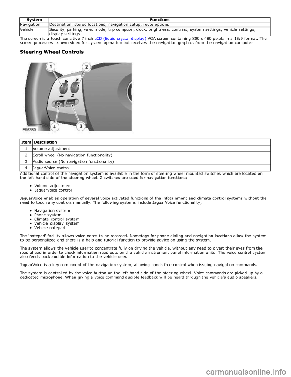
Steering Wheel Controls
Item Description 1 Volume adjustment 2 Scroll wheel (No navigation functionality) 3 Audio source (No navigation functionality) 4 JaguarVoice control Additional control of the navigation system is available in the form of steering wheel mounted switches which are located on
the left hand side of the steering wheel. 2 switches are used for navigation functions;
Volume adjustment
JaguarVoice control
JaguarVoice enables operation of several voice activated functions of the infotainment and climate control systems without the
need to touch any controls manually. The following systems include JaguarVoice functionality;
Navigation system
Phone system
Climate control system
Vehicle display system
Vehicle notepad
The 'notepad' facility allows voice notes to be recorded. Nametags for phone dialing and navigation locations allow the system
to be personalized and there is a help and tutorial function to provide advice on using the system.
The system allows the vehicle user to concentrate fully on driving the vehicle, without any need to divert their eyes from the
road ahead in order to check information read outs on the vehicle instrument panel information units. The voice control system
also feeds back audible information to the vehicle user.
JaguarVoice is a key component of the navigation system, allowing hands free control when issuing navigation commands.
The system is controlled by the voice button on the left hand side of the steering wheel. Voice commands are picked up by a
dedicated microphone. When giving a voice command audible feedback will be heard through the vehicle’s audio speakers.
Page 2013 of 3039
Symptom Possible Cause Action unit's battery is not
holding charge and
requires replacement Unable to select specific
content on the iPOD® (ie: an
individual artist, album or
song)
Content/sound files
corrupted or incompatible
with the iPOD®
Check if files/content can be accessed by iPOD® when
it is disconnected from the audio input control module.
If fault persists, advise customer to renew or replace
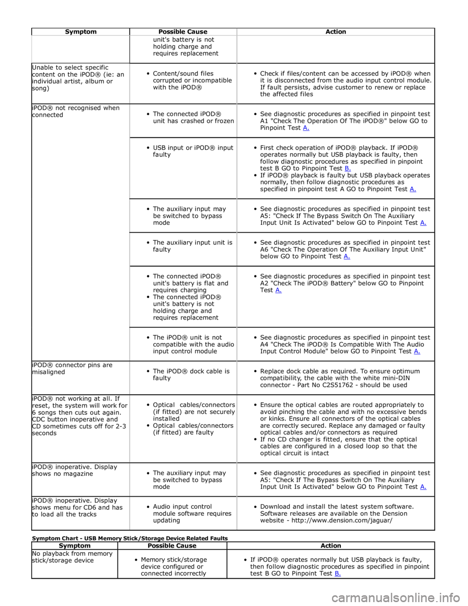
the affected files iPOD® not recognised when
connected
The connected iPOD®
unit has crashed or frozen
See diagnostic procedures as specified in pinpoint test
A1 "Check The Operation Of The iPOD®" below GO to
Pinpoint Test A.
USB input or iPOD® input
faulty
First check operation of iPOD® playback. If iPOD®
operates normally but USB playback is faulty, then
follow diagnostic procedures as specified in pinpoint
test B GO to Pinpoint Test B. If iPOD® playback is faulty but USB playback operates
normally, then follow diagnostic procedures as
specified in pinpoint test A GO to Pinpoint Test A.
The auxiliary input may
be switched to bypass
mode
See diagnostic procedures as specified in pinpoint test
A5: "Check If The Bypass Switch On The Auxiliary
Input Unit Is Activated" below GO to Pinpoint Test A.
The auxiliary input unit is
faulty
See diagnostic procedures as specified in pinpoint test
A6 "Check The Operation Of The Auxiliary Input Unit"
below GO to Pinpoint Test A.
The connected iPOD®
unit's battery is flat and
requires charging
The connected iPOD®
unit's battery is not
holding charge and
requires replacement
See diagnostic procedures as specified in pinpoint test
A2 "Check The iPOD® Battery" below GO to Pinpoint
Test A.
The iPOD® unit is not
compatible with the audio
input control module
See diagnostic procedures as specified in pinpoint test
A4 "Check The iPOD® Is Compatible With The Audio
Input Control Module" below GO to Pinpoint Test A. iPOD® connector pins are
misaligned
The iPOD® dock cable is
faulty
Replace dock cable as required. To ensure optimum
compatibility, the cable with the white mini-DIN
connector - Part No C2S51762 - should be used iPOD® not working at all. If
reset, the system will work for
6 songs then cuts out again.
CDC button inoperative and
CD sometimes cuts off for 2-3
seconds
Optical cables/connectors
(if fitted) are not securely
installed
Optical cables/connectors
(if fitted) are faulty
Ensure the optical cables are routed appropriately to
avoid pinching the cable and with no excessive bends
or kinks. Ensure all connectors of the optical cables
are correctly secured. Replace any damaged or faulty
optical cables and/or connectors as required
If no CD changer is fitted, ensure that the optical
cables are configured in a closed loop so that the
optical circuit is intact iPOD® inoperative. Display
shows no magazine
The auxiliary input may
be switched to bypass
mode
See diagnostic procedures as specified in pinpoint test
A5: "Check If The Bypass Switch On The Auxiliary
Input Unit Is Activated" below GO to Pinpoint Test A. iPOD® inoperative. Display
shows menu for CD6 and has
to load all the tracks
Audio input control
module software requires
updating
Download and install the latest system software.
Software releases are available on the Dension
website - http://www.dension.com/jaguar/ Symptom Chart - USB Memory Stick/Storage Device Related Faults
Symptom Possible Cause Action No playback from memory
stick/storage device
Memory stick/storage
device configured or
connected incorrectly
If iPOD® operates normally but USB playback is faulty,
then follow diagnostic procedures as specified in pinpoint
test B GO to Pinpoint Test B.
Page 2017 of 3039
Is the USB extension cable securely pushed into the USB connection port on the audio input control module
Yes
Replace the USB extension cable
No
Secure connections and retest B4: CHECK THE CAPACITY OF THE MEMORY STICK/STORAGE DEVICE
NOTE: The higher the capacity of the memory stick is the longer it takes to register with the audio input control module
and power up. The maximum permitted capacity is 8 Gigabytes 1 Check the storage capacity of the memory stick/storage device does not exceed 8 Gigabytes Is the storage capacity of the memory stick/storage device 8 Gigabytes or less?
Yes
High capacity devices may require longer to register and should be allowed up to two minutes to power up
following connection to the USB port. If memory stick fails to power up after two minutes, suspect a
faulty memory stick GO to B2. or USB extension cable GO to B3. No
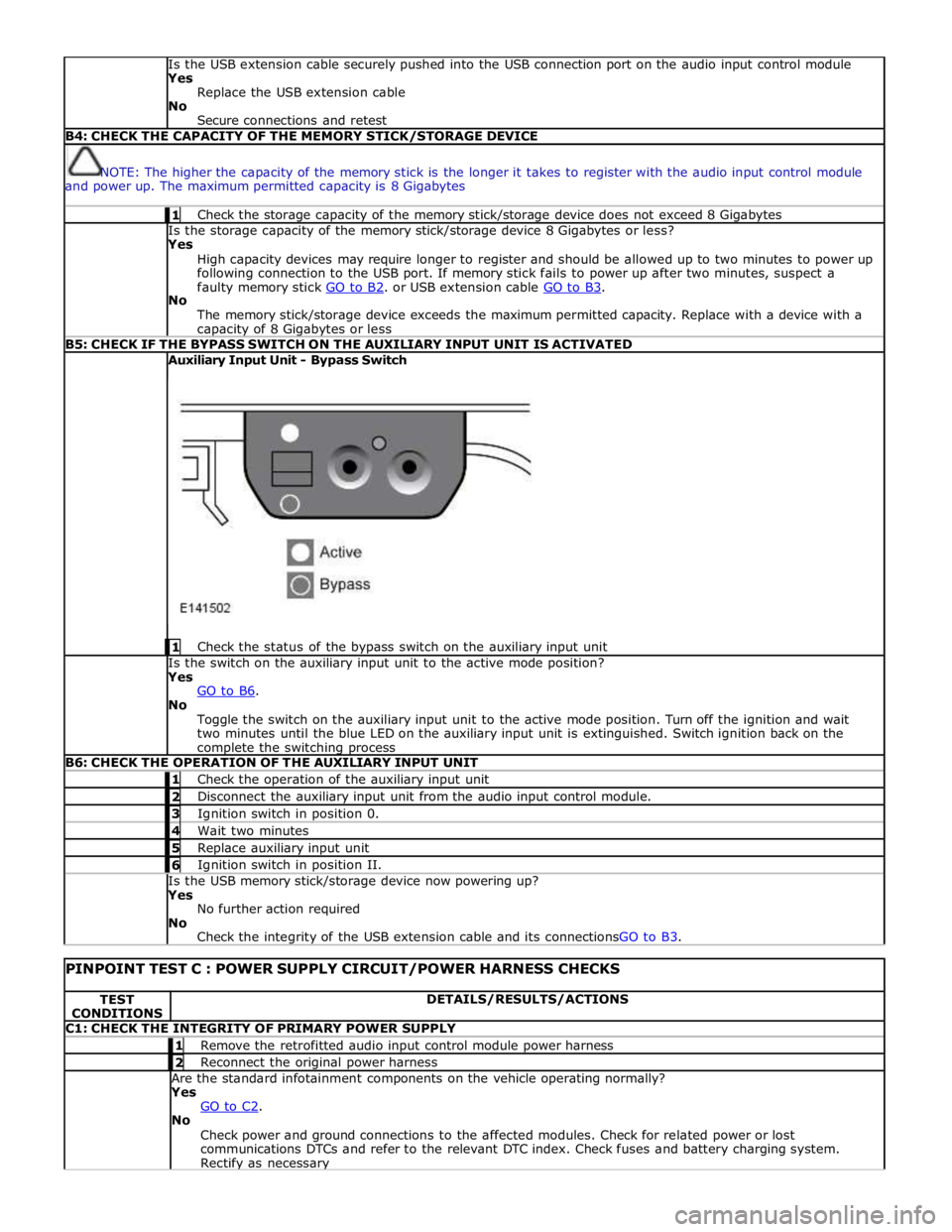
The memory stick/storage device exceeds the maximum permitted capacity. Replace with a device with a capacity of 8 Gigabytes or less B5: CHECK IF THE BYPASS SWITCH ON THE AUXILIARY INPUT UNIT IS ACTIVATED Auxiliary Input Unit - Bypass Switch
1 Check the status of the bypass switch on the auxiliary input unit Is the switch on the auxiliary input unit to the active mode position?
Yes
GO to B6. No
Toggle the switch on the auxiliary input unit to the active mode position. Turn off the ignition and wait
two minutes until the blue LED on the auxiliary input unit is extinguished. Switch ignition back on the complete the switching process B6: CHECK THE OPERATION OF THE AUXILIARY INPUT UNIT 1 Check the operation of the auxiliary input unit 2 Disconnect the auxiliary input unit from the audio input control module. 3 Ignition switch in position 0. 4 Wait two minutes 5 Replace auxiliary input unit 6 Ignition switch in position II. Is the USB memory stick/storage device now powering up?
Yes
No further action required
No
Check the integrity of the USB extension cable and its connectionsGO to B3.
PINPOINT TEST C : POWER SUPPLY CIRCUIT/POWER HARNESS CHECKS TEST
CONDITIONS DETAILS/RESULTS/ACTIONS C1: CHECK THE INTEGRITY OF PRIMARY POWER SUPPLY 1 Remove the retrofitted audio input control module power harness 2 Reconnect the original power harness Are the standard infotainment components on the vehicle operating normally?
Yes
GO to C2. No
Check power and ground connections to the affected modules. Check for related power or lost
communications DTCs and refer to the relevant DTC index. Check fuses and battery charging system. Rectify as necessary
Page 2027 of 3039
by Field Effect Transistors (FET's). The FET's can detect overloads and short circuits and respond to heat generated by
increased current flow caused by a short circuit.
On a normal conventionally protected circuit this would cause a fuse to blow. The FET's respond to the heat increase and
disconnect the power supply to the affected circuit. When the fault is rectified or the FET has cooled, the FET will reset and
operate the circuit normally. If the fault persists the FET will cycle, disconnecting and reconnecting the power supply.
The CJB and the RJB store fault codes which can be retrieved using a Jaguar approved diagnostic system. The fault code will identify that there is a fault on a particular output circuit which will assist with fault diagnosis and detection.
Alarm Indications
The exterior lighting system is used for alarm arm and disarm requests to show alarm system status.
When the driver locks and arms the vehicle, a visual indication of a successful lock and arm request is displayed to the driver
by a single flash of the hazard flashers. If the vehicle is superlocked, then the hazard flashers will flash a second time (200 ms
off and 200 ms on) to confirm the superlock request.
If the alarm is activated, the hazard flashers are operated for 10, 30 second cycles of 200 ms on and 200 ms off, with a 10
second delay between each cycle.
NOTE: On North American Specification (NAS) vehicles, the delay between the cycle when the alarm is activated is 60
seconds.
Lights on Warning
When the ignition is in the off power mode 0 or accessory power mode 4 and the lighting control switch is in the side lamp or
headlamp position, a warning chime will sound if the driver's door is opened. This indicates to the driver that the exterior
lights have been left switched on.
The chime is generated from the instrument cluster sounder on receipt of a lights on signal, a driver's door open signal and an
ignition off power mode 0 or accessory power mode 4 signal via a medium speed CAN bus signal from the CJB. Headlamp Timer
The RJB controls the headlamp timer function which allows the headlamps to remain on for a period of time after leaving the vehicle. This is a driver convenience feature which illuminates the driveway after leaving the vehicle.
To operate the timer function the lighting control switch must be in one of the three headlamp timer positions when the
ignition status is changed from ignition on power mode 6 to the off power mode 0. The timer function will then be initiated and
the low beam headlamps will be illuminated for the selected timer period.
NOTE: If the lighting switch is in the AUTO position, the headlamp timer will not function when the ignition is changed to
off power mode 0.
When the lighting control switch is in the autolamp exit delay position, the lighting control switch reference voltage flows
through 4 of the resistors. The returned signal voltage is detected by the instrument cluster which outputs a message on the
medium speed CAN bus to the RJB that autolamps has been selected.
Depending on the selected exit delay position, the reference voltage to the autolamp exit delay switch is routed through 3, 2
or 1 resistors which is detected by the instrument cluster. The cluster outputs a message on the medium speed CAN bus to the RJB that autolamp exit delay period has been selected at 30, 60 or 120 seconds respectively. Crash Signal Activation
When a crash signal is transmitted from the RCM (restraints control module), the RJB activates the hazard flashers. The hazard flashers continue to operate until the ignition is in the off power mode 0 or accessory power mode 6. Once this ignition state
has occurred, the RCM will cease to transmit the crash signal.
LIGHTING CONTROL SWITCH
The instrument cluster outputs 2 reference voltages to the rotary lighting control switch; one feed being supplied to the light
selection function of the switch and the second feed being supplied to the auto headlamp exit delay function. The switch
position is determined by instrument cluster by the change in returned signal voltage which is routed through up to 4 resistors
in series depending on the selection made.
OFF - When the lighting control switch is in the off position, the reference voltage flows through 1 of the resistors. The
returned signal voltage is detected by the instrument cluster which outputs a message on the medium speed CAN bus to the CJB that no lighting selection is made. The reference voltage to the auto headlamp exit delay switch is routed through 4 resistors which is detected by the instrument cluster which outputs a message on the medium speed CAN bus to the CJB that auto headlamp or exit delay has not been selected.
SIDE LAMPS - When the lighting control switch is in the side lamp position, the reference voltage flows through 2 of the
resistors. The returned signal voltage is detected by the instrument cluster which outputs a message on the medium speed
CAN bus to the CJB to activate the side lamps. The reference voltage to the autolamp exit delay switch is routed through 4 resistors which is detected by the instrument cluster which outputs a message on the medium speed CAN bus to the CJB that auto headlamp or exit delay has not been selected.
HEADLAMPS - When the lighting control switch is in the headlamp position, the reference voltage flows through 3 of the
Page 2033 of 3039
Halogen Low/high Beam Headlamp
The halogen low/high beam headlamp uses a projector lens, similar to the xenon headlamp. The projector module comprises
an ellipsoidal lens and a reflector. The projector reflector collects the light produced by the halogen bulb and projects the light
into a focal plane containing a shield. The contour of the shield is projected onto the road by the lens. The low/high beam
bulbs are quartz halogen and are retained in the headlamp unit with conventional wire retaining clips.
A tourist lever mechanism is located on the right hand side of the projector module. This mechanism moves a flap to blank off
a portion of the beam spread to enable the vehicle to be driven in opposite drive hand markets without applying blanking
decals to the headlamp lens. The beam is changed by removing the access cover at the rear of the lamp assembly and moving
a small lever located near the bulb holder, at the side of the projector.
Halogen High Beam Headlamp - Xenon and Halogen
The xenon and halogen headlamps use a complex surface reflector for the halogen fill in high beam lamp only lighting unit,
which is of the same design on both headlamp types. This type of reflector has the reflector divided into separate parabolic
segments, with each segment having a different focal length.
The high beam headlamp bulbs are quartz halogen and are retained in the headlamp unit with conventional wire retaining
clips.
Cornering Lamps
NOTE: The cornering lamps are not fitted to NAS vehicles.
The cornering lamps are an optional feature designed to illuminate the direction of travel when cornering at low speeds. The
design of the lens projects a spread of light from the vehicle at approximately 45 degrees to the vehicle axis. The cornering
lamp is incorporated into the headlamp assembly and shares the same housing as the low beam headlamp. The cornering lamp
uses a 35W Halogen H8 bulb which is permanently located in an integral holder which is connected on the headlamp housing.
The holder is located in an aperture in the headlamp housing and rotated to lock. The bulb is accessible via a removable cover
on the base of the headlamp housing.
The cornering lamps are controlled by the LH steering column multifunction switch with the lighting control switch in the headlamp position and the ignition in power mode 6. The cornering lamps are supplied power via the ignition circuit to ensure
that they do not function with the headlamp delay feature. The cornering lamps are deactivated if the vehicle speed exceeds
25 mph (40 km/h). Only one cornering lamp will illuminate at any one time. If the left hand turn signal indicators are selected
on, the left hand cornering lamp will be illuminated and vice versa, providing the vehicle speed and lighting control switch
positions are correct.
Static Bending Lamps
NOTE: The static bending lamps are not fitted to NAS vehicles.
The static bending lamps are designed to illuminate the direction of travel when cornering at low speeds. The static bending
lamp functionality, which is controlled by the CJB and the headlamp leveling module, operates using inputs from the steering angle sensor and vehicle speed information from the ABS (anti-lock brake system) module. The static bending lamp is
incorporated into the headlamp assembly and shares the same housing as the low beam headlamp. The design of the lens
projects a spread of light from the vehicle at approximately 45 degrees to the vehicle axis. The static bending lamp uses a
35W Halogen H8 bulb which locates in a holder which is connected via wires to the main connector on the headlamp housing.
The holder is located in an aperture in the headlamp housing and rotated to lock. The bulb is accessible via a removable cover
at the rear of the headlamp housing.
The static bending lamps operate with a steering angle sensor CAN bus signal which is received by the CJB. The CJB monitors this signal and vehicle speed and activates the static bending lamp bulb. When the operation parameters of the lamp are
reached, the CJB fades the static bending lamp bulb on using a PWM (pulse width modulation) voltage over a period of approximately 2 seconds. When the lamp is switched off, the CJB fades the bulb off by decreasing the PWM voltage in a linear manner depending on steering angle and vehicle speed. The cornering lamps can only be active for a maximum of 3 minutes.
NOTE: Static bending lamps only operate when the transmission is in DRIVE or in SPORT.
Turn Signal Indicators
The turn signal indicator lamp is incorporated into the outer part of the headlamp assembly. The turn signal indicator lamp
uses a PY21W bayonet orange colored bulb in ROW markets, a S8W 27/7W wedge bulb is used in NAS markets. The bulb is
fitted into a holder which connects with contacts in the headlamp housing. The holder is fitted into an aperture in the
headlamp housing and rotated to lock into position.
When active, the turn signal indicator lamps will flash at a frequency cycle of 380ms on and 380ms off. If a bulb fails, the
remaining turn signal lamps bulbs continue to flash at normal speed. The turn signal indicators in the instrument cluster will
flash at double speed to indicate the bulb failure to the driver.
Side Lamps
The side lamp is located between the headlamp projector module and the high bean headlamp. The side lamp uses a W5W
wedge fitting bulb which locates in a holder which connected via wires to the main connector on the headlamp housing. The
holder is a push fit into a receptacle in the headlamp housing. The bulb is accessible by removal of the inner cover on the rear
of the headlamp housing. Access to the bulb requires removal of the headlamp from the vehicle. The side lamps are operated
by selecting side lamps or headlamps on the lighting control switch. The side lamps are functional at all times and are