relay JAGUAR XFR 2010 1.G Manual Online
[x] Cancel search | Manufacturer: JAGUAR, Model Year: 2010, Model line: XFR, Model: JAGUAR XFR 2010 1.GPages: 3039, PDF Size: 58.49 MB
Page 2563 of 3039

Roof Opening Panel - Roof Opening Panel
Diagnosis and Testing
Principle of Operation Published: 11-May-2011
For a detailed description of the roof opening panel, refer to the relevant Description and Operation sections in the workshop
manual. REFER to: (501-17 Roof Opening Panel)
Roof Opening Panel (Description and Operation), Roof Opening Panel (Description and Operation), Roof Opening Panel (Description and Operation).
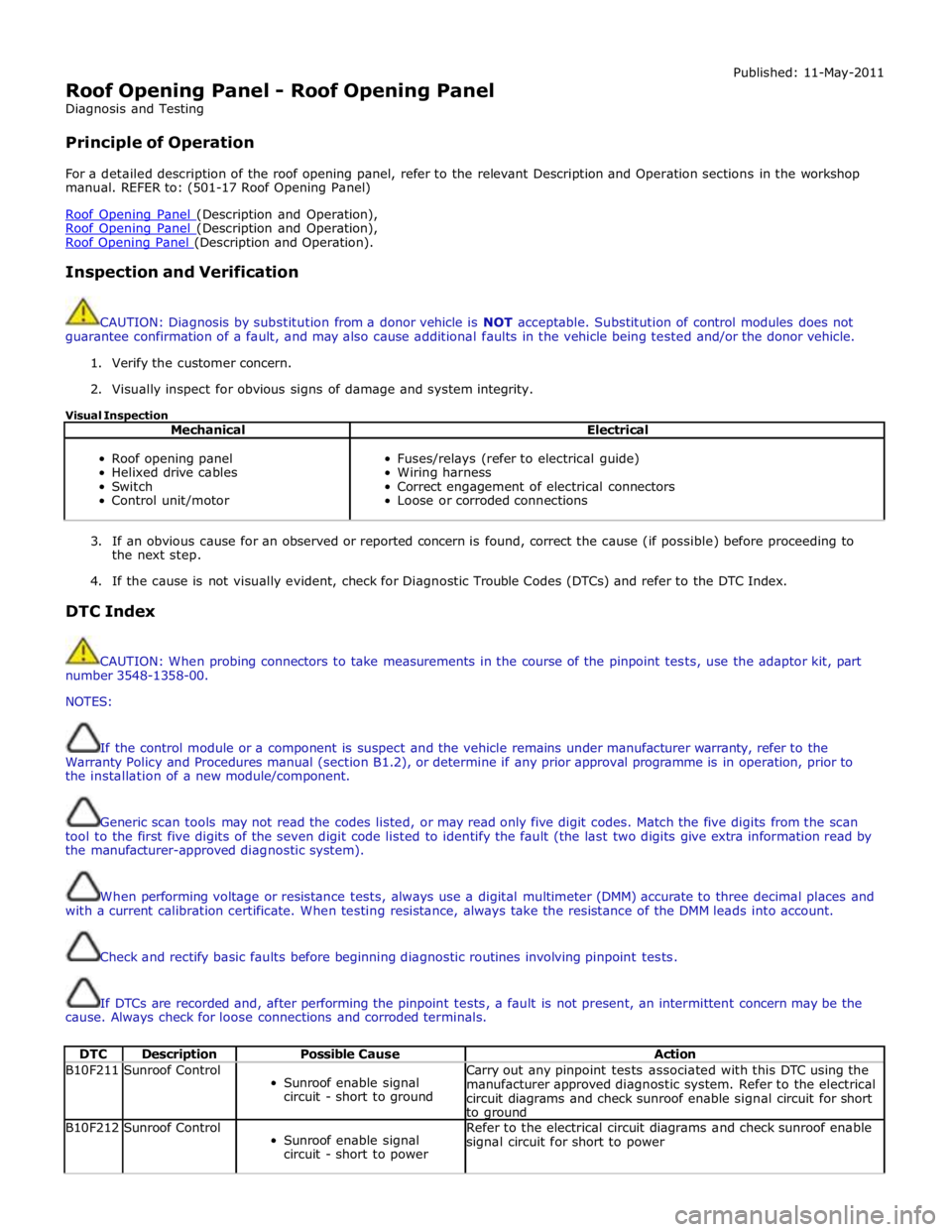
Inspection and Verification
CAUTION: Diagnosis by substitution from a donor vehicle is NOT acceptable. Substitution of control modules does not
guarantee confirmation of a fault, and may also cause additional faults in the vehicle being tested and/or the donor vehicle.
1. Verify the customer concern.
2. Visually inspect for obvious signs of damage and system integrity.
Visual Inspection
Mechanical Electrical
Roof opening panel
Helixed drive cables
Switch
Control unit/motor
Fuses/relays (refer to electrical guide)
Wiring harness
Correct engagement of electrical connectors
Loose or corroded connections
3. If an obvious cause for an observed or reported concern is found, correct the cause (if possible) before proceeding to
the next step.
4. If the cause is not visually evident, check for Diagnostic Trouble Codes (DTCs) and refer to the DTC Index.
DTC Index
CAUTION: When probing connectors to take measurements in the course of the pinpoint tests, use the adaptor kit, part
number 3548-1358-00.
NOTES:
If the control module or a component is suspect and the vehicle remains under manufacturer warranty, refer to the
Warranty Policy and Procedures manual (section B1.2), or determine if any prior approval programme is in operation, prior to
the installation of a new module/component.
Generic scan tools may not read the codes listed, or may read only five digit codes. Match the five digits from the scan
tool to the first five digits of the seven digit code listed to identify the fault (the last two digits give extra information read by
the manufacturer-approved diagnostic system).
When performing voltage or resistance tests, always use a digital multimeter (DMM) accurate to three decimal places and
with a current calibration certificate. When testing resistance, always take the resistance of the DMM leads into account.
Check and rectify basic faults before beginning diagnostic routines involving pinpoint tests.
If DTCs are recorded and, after performing the pinpoint tests, a fault is not present, an intermittent concern may be the
cause. Always check for loose connections and corroded terminals.
DTC Description Possible Cause Action B10F211 Sunroof Control
Sunroof enable signal
circuit - short to ground Carry out any pinpoint tests associated with this DTC using the
manufacturer approved diagnostic system. Refer to the electrical
circuit diagrams and check sunroof enable signal circuit for short
to ground B10F212 Sunroof Control
Sunroof enable signal
circuit - short to power Refer to the electrical circuit diagrams and check sunroof enable
signal circuit for short to power
Page 2615 of 3039

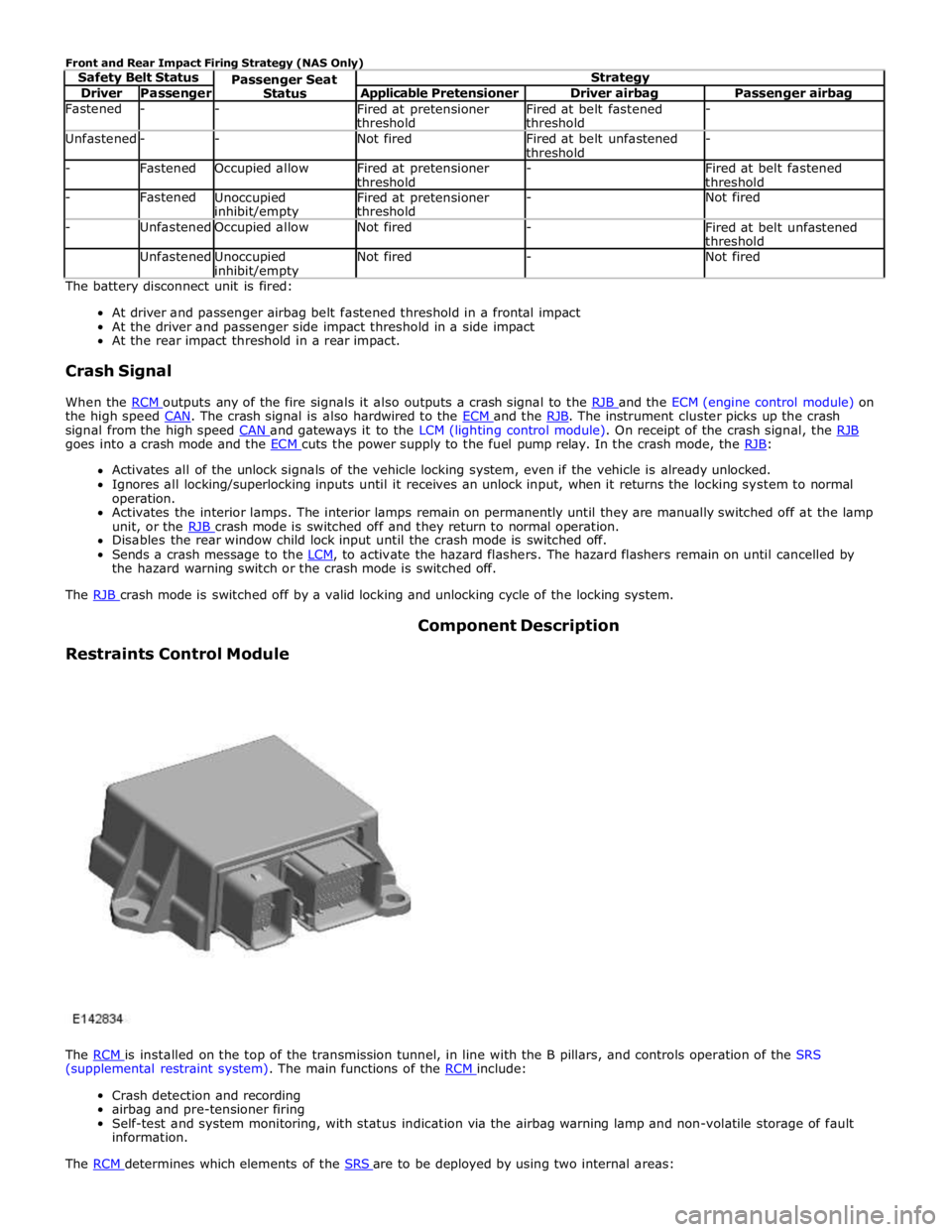
Driver Passenger Applicable Pretensioner Driver airbag Passenger airbag Fastened - -
Fired at pretensioner
threshold Fired at belt fastened
threshold - Unfastened - - Not fired
Fired at belt unfastened
threshold - - Fastened Occupied allow
Fired at pretensioner
threshold -
Fired at belt fastened
threshold - Fastened
Unoccupied inhibit/empty Fired at pretensioner
threshold - Not fired - Unfastened Occupied allow Not fired -
Fired at belt unfastened
threshold Unfastened
Unoccupied inhibit/empty Not fired - Not fired The battery disconnect unit is fired:
At driver and passenger airbag belt fastened threshold in a frontal impact
At the driver and passenger side impact threshold in a side impact
At the rear impact threshold in a rear impact.
Crash Signal
When the RCM outputs any of the fire signals it also outputs a crash signal to the RJB and the ECM (engine control module) on the high speed CAN. The crash signal is also hardwired to the ECM and the RJB. The instrument cluster picks up the crash signal from the high speed CAN and gateways it to the LCM (lighting control module). On receipt of the crash signal, the RJB goes into a crash mode and the ECM cuts the power supply to the fuel pump relay. In the crash mode, the RJB: Activates all of the unlock signals of the vehicle locking system, even if the vehicle is already unlocked.
Ignores all locking/superlocking inputs until it receives an unlock input, when it returns the locking system to normal
operation.
Activates the interior lamps. The interior lamps remain on permanently until they are manually switched off at the lamp
unit, or the RJB crash mode is switched off and they return to normal operation. Disables the rear window child lock input until the crash mode is switched off.
Sends a crash message to the LCM, to activate the hazard flashers. The hazard flashers remain on until cancelled by the hazard warning switch or the crash mode is switched off.
The RJB crash mode is switched off by a valid locking and unlocking cycle of the locking system.
Restraints Control Module Component Description
The RCM is installed on the top of the transmission tunnel, in line with the B pillars, and controls operation of the SRS (supplemental restraint system). The main functions of the RCM include:
Crash detection and recording
airbag and pre-tensioner firing
Self-test and system monitoring, with status indication via the airbag warning lamp and non-volatile storage of fault
information.
The RCM determines which elements of the SRS are to be deployed by using two internal areas: