relay JAGUAR XFR 2010 1.G Service Manual
[x] Cancel search | Manufacturer: JAGUAR, Model Year: 2010, Model line: XFR, Model: JAGUAR XFR 2010 1.GPages: 3039, PDF Size: 58.49 MB
Page 1589 of 3039
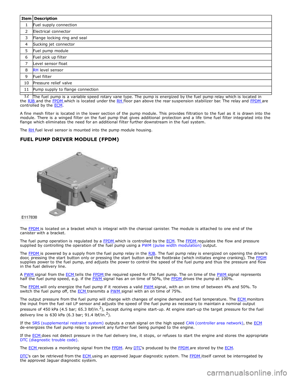
1 Fuel supply connection 2 Electrical connector 3 Flange locking ring and seal 4 Sucking jet connector 5 Fuel pump module 6 Fuel pick up filter 7 Level sensor float 8 RH level sensor 9 Fuel filter 10 Pressure relief valve 11 Pump supply to flange connection 12 The fuel pump is a variable speed rotary vane type. The pump is energized by the fuel pump relay which is located in the RJB and the FPDM which is located under the RH floor pan above the rear suspension stabilizer bar. The relay and FPDM are controlled by the ECM.
A fine mesh filter is located in the lower section of the pump module. This provides filtration to the fuel as it is drawn into the
module. There is a winged filter on the fuel pump that gives additional protection and a life time fuel filter integrated into the
flange which eliminates the need for an additional filter further downstream in the fuel system.
The RH fuel level sensor is mounted into the pump module housing.
FUEL PUMP DRIVER MODULE (FPDM)
The FPDM is located on a bracket which is integral with the charcoal canister. The module is attached to one end of the canister with a bracket.
The fuel pump operation is regulated by a FPDM which is controlled by the ECM. The FPDM regulates the flow and pressure supplied by controlling the operation of the fuel pump using a PWM (pulse width modulation) output.
The FPDM is powered by a supply from the fuel pump relay in the RJB. The fuel pump relay is energized on opening the driver's door, pressing the start button only or pressing the start button and the footbrake (which initiates engine cranking). The FPDM supplies power to the fuel pump, and adjusts the power to control the speed of the fuel pump and thus the pressure and flow
in the fuel delivery line.
A PWM signal from the ECM tells the FPDM the required speed for the fuel pump. The on time of the PWM signal represents half the fuel pump speed, e.g. if the PWM signal has an on time of 50%, the FPDM drives the pump at 100%.
The FPDM will only energize the fuel pump if it receives a valid PWM signal, with an on time of between 4% and 50%. To switch the fuel pump off, the ECM transmits a PWM signal with an on time of 75%.
The output pressure from the fuel pump will change with changes of engine demand and fuel temperature. The ECM monitors the input from the fuel rail LP sensor and adjusts the speed of the fuel pump as necessary to maintain a nominal output
pressure of 450 kPa (4.5 bar; 65.3 lbf/in.2
), except during engine start-up. At engine start-up the target pressure for the fuel
delivery line is 630 kPa (6.3 bar; 91.4 lbf/in.2
).
If the SRS (supplemental restraint system) outputs a crash signal on the high speed CAN (controller area network), the ECM de-energizes the fuel pump relay to prevent any further fuel being pumped to the engine.
If the ECM does not detect pressure in the fuel delivery line, it stops, or refuses to start the engine and stores the appropriate DTC (diagnostic trouble code).
The ECM receives a monitoring signal from the FPDM. Any DTC's produced by the FPDM are stored by the ECM.
DTC's can be retrieved from the ECM using an approved Jaguar diagnostic system. The FPDM itself cannot be interrogated by the approved Jaguar diagnostic system.
Page 1596 of 3039

Visual Inspection
Mechanical Electrical
Low/contaminated fuel
Fuel supply/return line(s)
Fuel tank and filler pipe
Fuel leak(s)
Fuel filler cap
Fuel filter
Push connect fittings
Fuel pump
Fuses
Links
Relays
Fuel Pump Driver Module (FPDM)
Fuel pump module
Sensor(s)
Engine control module (ECM)
Rear Junction Box (RJB)
Restraints Control Module (RCM)
3. If an obvious cause for an observed or reported concern is found, correct the cause (if possible) before proceeding to
the next step
4. If the cause is not visually evident, verify the symptom and refer to the Symptom Chart, alternatively check for
Diagnostic Trouble Codes (DTCs) and proceed to the DTC Index
Symptom Chart
Symptom Possible Causes Action Engine cranks, but does not
fire
Engine breather system
disconnected/restricted
Ignition system
Fuel system
Electronic engine control
Ensure the engine breather system is free from
restriction and is correctly installed
Check for ignition system, fuel system and electronic
engine control DTCs and refer to the relevant DTC
Index Engine cranks and fires, but
will not start
Evaporative emissions purge
valve
Fuel pump
Spark plugs
HT short to ground (tracking)
check rubber boots for
cracks/damage
Ignition system
Check for evaporative emissions, fuel system and
ignition system related DTCs and refer to the
relevant DTC Index Difficult cold start
Engine coolant level/anti-
freeze content
Battery
Electronic engine controls
Fuel pump
Purge valve
Check the engine coolant level and condition
Ensure the battery is in a fully charged and
serviceable condition
Check for electronic engine controls, engine
emissions, fuel system and evaporative emissions
system related DTCs and refer to the relevant DTC
Index Difficult hot start
Injector leak
Electronic engine control
Purge valve
Fuel pump
Ignition system
Check for injector leak, install new injector as
required
Check for electronic engine controls, evaporative
emissions, fuel system, ignition system and engine
emission system related DTCs and refer to the
relevant DTC Index Difficult to start after hot
soak (vehicle standing,
engine off, after engine has
reached operating
temperature)
Injector leak
Electronic engine control
Purge valve
Fuel pump
Ignition system
Check for injector leak, install new injector as
required
Check for electronic engine controls, evaporative
emissions, fuel system, ignition system and engine
emission system related DTCs and refer to the
relevant DTC Index Engine stalls soon after start
Breather system
disconnected/restricted
ECM relay
Electronic engine control
Ignition system
Air intake system restricted
Air leakage
Fuel lines
Ensure the engine breather system is free from
restriction and is correctly installed
Check for electronic engine control, ignition system
and fuel system related DTCs and refer to the
relevant DTC Index
Check for blockage in air filter element and air
intake system
Check for air leakage in air intake system Engine hesitates/poor
acceleration
Fuel pressure, fuel pump,
fuel lines
Injector leak
Air leakage
Check for fuel system related DTCs and refer to the
relevant DTC Index
Check for injector leak, install new injector as
required www.JagDocs.com
Page 1690 of 3039
Published: 11-May-2011
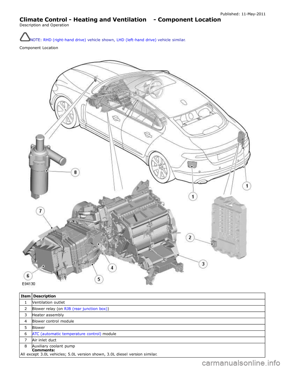
Climate Control - Heating and Ventilation - Component Location
Description and Operation
NOTE: RHD (right-hand drive) vehicle shown, LHD (left-hand drive) vehicle similar.
Component Location
Item Description 1 Ventilation outlet 2 Blower relay (on RJB (rear junction box)) 3 Heater assembly 4 Blower control module 5 Blower 6 ATC (automatic temperature control) module 7 Air inlet duct 8 Auxiliary coolant pump Comments:
All except 3.0L vehicles; 5.0L version shown, 3.0L diesel version similar.
Page 1693 of 3039
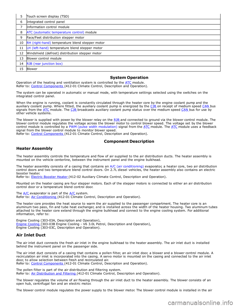
Touch screen display (TSD) 6 Integrated control panel 7 Information control module 8 ATC (automatic temperature control) module 9 Face/Feet distribution stepper motor 10 RH (right-hand) temperature blend stepper motor 11 LH (left-hand) temperature blend stepper motor 12 Windshield (defrost) distribution stepper motor 13 Blower control module 14 RJB (rear junction box) 15 Blower
System Operation
Operation of the heating and ventilation system is controlled by the ATC module. Refer to: Control Components (412-01 Climate Control, Description and Operation).
The system can be operated in automatic or manual mode, with temperature settings selected using the switches on the
integrated control panel.
When the engine is running, coolant is constantly circulated through the heater core by the engine coolant pump and the
auxiliary coolant pump. Where fitted, the auxiliary coolant pump is energized by the CJB on receipt of medium speed CAN bus signals from the ATC module. The CJB broadcasts auxiliary coolant pump status over the medium speed CAN bus for use by other vehicle systems.
The blower is supplied with power by the blower relay on the RJB and connected to ground via the blower control module. The blower control module regulates the voltage across the blower motor to control blower speed. The voltage set by the blower
control module is controlled by a PWM (pulse width modulation) signal from the ATC module. The ATC module uses a feedback signal from the blower control module to monitor blower speed.
Refer to: Control Components (412-01 Climate Control, Description and Operation).
Heater Assembly Component Description
The heater assembly controls the temperature and flow of air supplied to the air distribution ducts. The heater assembly is
mounted on the vehicle centerline, between the instrument panel and the engine bulkhead.
The heater assembly consists of a casing that contains an A/C (air conditioning) evaporator, a heater core, two air distribution
control doors and two temperature blend control doors. On 2.7L diesel vehicles, the heater assembly also contains an electric
booster heater.
Refer to: Electric Booster Heater (412-02 Auxiliary Climate Control, Description and Operation).
Mounted on the heater casing are four stepper motors. Each of the stepper motors is connected to either an air distribution
control door or a temperature blend control door.
The A/C evaporator is part of the A/C system. Refer to: Air Conditioning (412-01 Climate Control, Description and Operation).
The heater core provides the heat source to warm the air supplied to the passenger compartment. The heater core is an
aluminum two pass, fin and tube heat exchanger, and is installed across the width of the heater housing. Two aluminum tubes
attached to the heater core extend through the engine bulkhead and connect to the engine cooling system. For additional
information, refer to:
Engine Cooling (303-03A, Description and Operation),
Engine Cooling (303-03B Engine Cooling - V6 3.0L Petrol, Description and Operation), Engine Cooling (303-03C, Description and Operation).
Air Inlet Duct
The air inlet duct connects the fresh air inlet in the engine bulkhead to the heater assembly. The air inlet duct is installed
behind the instrument panel on the passenger side.
The air inlet duct consists of a casing that contains a pollen filter, an air inlet door, a blower and a blower control module. A
recirculation air inlet is incorporated into the casing. A servo motor is mounted on the casing and connected to the air inlet
door, to allow selection between fresh and recirculated air.
Refer to: Control Components (412-01 Climate Control, Description and Operation). The pollen filter is part of the air distribution and filtering system.
Refer to: Air Distribution and Filtering (412-01 Climate Control, Description and Operation).
The blower regulates the volume of air flowing through the air inlet duct to the heater assembly. The blower consists of an
open hub, centrifugal fan and an electric motor.
The blower control module regulates the power supply to the blower motor. The blower control module is installed in the air
Page 1710 of 3039
control switch on the integrated control panel or the + and - soft buttons on the touch screen display (TSD). The ATC module also adjusts blower speed to compensate for the ram effect on inlet air produced by forward movement of the vehicle. As
vehicle speed and ram effect increases, blower motor speed is reduced, and vice versa.
Air Distribution Control
Two air distribution doors are used to direct air into the passenger compartment. The doors are operated by stepper motors,
which are controlled by the ATC module using LIN bus messages.
When the A/C system is in automatic mode, the ATC module automatically controls air distribution into the passenger compartment in line with its 'comfort' algorithm. Automatic control is overridden if any of the TSD air distribution soft buttons
are selected. Air distribution in the passenger compartment will remain as selected until the 'Auto' switch is pressed or a
different manual selection is made.
A/C Compressor Control
When A/C is selected the ATC module maintains the evaporator at an operating temperature that varies with the passenger compartment cooling requirements. If the requirement for cooled air decreases, the ATC module raises the evaporator operating temperature by reducing the flow of refrigerant provided by the A/C compressor. The ATC module closely controls the rate of temperature increase to avoid introducing moisture into the passenger compartment.
If the requirement for cooled air increases, the ATC module lowers the evaporator operating temperature by increasing the flow of refrigerant provided by the A/C compressor.
When A/C is off, the compressor current signal supplied by the ATC module holds the A/C compressor solenoid valve in the minimum flow position, effectively switching off the A/C function.
The ATC module incorporates limits for the operating pressure of the refrigerant system. If the system approaches the high pressure limit, the compressor current signal is progressively reduced until the system pressure decreases. If the system falls
below the low pressure limit, the compressor current signal is held at its lowest setting so that the A/C compressor is maintained at its minimum stroke. This avoids depletion of the lubricant from the A/C compressor.
A/C Compressor Torque
The ATC module transmits refrigerant pressure and A/C compressor current values to the ECM (engine control module) over the medium speed then high speed CAN bus, using the CJB as a gateway. The ECM uses these values to calculate the torque being used to drive the A/C compressor. The ECM compares the calculated value with its allowable value and if necessary forces the ATC module to inhibit the A/C compressor by transmitting the 'ACClutchInhibit' CAN message. This forces the ATC module to reduce the drive current to the A/C compressor solenoid valve, which reduces refrigerant flow. This in turn reduces the torque required to drive the A/C compressor.
By reducing the maximum A/C compressor torque, the ECM is able to reduce the load on the engine when it needs to maintain vehicle performance or cooling system integrity.
Cooling Fan Control
The ATC module determines the amount of condenser cooling required from the refrigerant pressure sensor, since there is a direct relationship between the temperature and pressure of the refrigerant. The cooling requirement is broadcast to the ECM on the medium speed CAN bus. The ECM then controls the temperature of the condenser using the cooling fan.
Programmed Defrost
The programmed defrost DEF switch is located on the integrated control panel. When the switch is pressed, the ATC module instigates the programmed defrost function. When selected, the ATC module configures the system as follows:
Automatic mode off.
A/C on. Selected temperature unchanged.
Air inlet set to fresh air.
Air distribution set to windshield.
Blower speed set to level 6.
Windshield heater (where fitted) and rear window heater on.
The programmed defrost function can be cancelled by one of the following:
Selecting any air distribution switch on the TSD.
Pressing the AUTO switch on the integrated control panel.
A second press of the DEF button.
Switching the ignition OFF.
The blower speed can be adjusted without terminating the programmed defrost function.
Rear Window Heater
Rear window heater operation is only enabled when the engine is running. The ATC module controls operation of the rear window heater using a relay in the RJB. When rear window heater operation is required, the ATC module broadcasts a message to the RJB on the medium speed CAN bus. On receipt of the message, the RJB energizes the relay by providing a ground path for the relay coil. This allows a battery feed to flow across the relay to power the rear window heater element.
Page 1711 of 3039
rear window heater switch is pressed or the engine stops.
Automatic operation during a journey is initiated when low ambient air temperatures are experienced and the vehicle has been
travelling for a set period of time above a threshold speed. In this instance, no feedback is given to the driver to inform him
the rear window heater is operational (the switch LED is not illuminated). The duration of heater operation is variable depending on the ambient air temperature, vehicle speed and the amount of time the vehicle has been travelling.
Windshield Heater (Where Fitted)
Windshield heater operation is only enabled when the engine is running. The ATC module controls operation of the windshield heater using two relays in the EJB (engine junction box). When windshield heater operation is required, the ATC module broadcasts a message to the CJB on the medium speed CAN bus. On receipt of the message, the CJB energizes the relays by providing a ground path for both relay coils. This allows a battery feed to flow across the relays to power the windshield left
and right heater elements.
There are two modes of windshield heater operation; manual and automatic.
Manual operation is activated by pressing the windshield heater switch on the integrated control panel. When the switch is
pressed, the status LED in the switch illuminates and the windshield heater elements are energized. Manual operation is discontinued when the windshield heater switch is pressed a second time, 5 minutes have elapsed (the heating phase), or the
engine stops. If manual operation is discontinued by the engine stopping, the previous heating phase is resumed if the engine
is re-started within 30 seconds.
There are two variants of automatic operation; automatic operation at the start of a journey and automatic operation during a
journey.
Automatic operation at the start of a journey is initiated if the ambient air temperature is below 5 °C (41 °F). In this instance,
the switch LED is illuminated and the heater elements are energized for 6.5 minutes. Automatic operation is discontinued if the windshield heater switch is pressed or the engine stops.
Automatic operation during a journey is initiated when low ambient air temperatures are experienced and the vehicle has been
travelling for a set period of time above a threshold speed. In this instance, no feedback is given to the driver to inform him
the windshield heater is operational (the switch LED is not illuminated) and the duration of operation is variable depending upon the ambient air temperature, vehicle speed and the amount of time the vehicle has been travelling.
Exterior Mirror Heaters
Operation of the exterior mirror heaters is fully automatic and not controllable by the driver. Exterior mirror heater operation is
determined by ambient air temperature and windshield wiper status. When ambient air temperature reaches a pre-determined
level, the ATC module broadcasts an exterior mirror heating request to the door modules over the medium speed CAN bus. On receipt of this message, the door modules provide feed and ground connections to both exterior mirror heater elements.
The amount of time the exterior mirror heaters are operational increases if the windshield wipers are switched on. This ensures
the mirrors remain mist free in damp and wet conditions, where there is an increased risk of misting.
Seat Heaters (Where Fitted)
There are four seat heater settings available; off, 1, 2 and 3, which can be selected on the home and climate control screens
of the TSD. The heat setting is relayed to the vehicle occupants through a graduated display on the TSD.
Operation of the heated seats is controlled by the ATC module. When the ATC module receives a heating request from the TSD, it broadcasts a message to the CJB over the medium speed CAN bus. The CJB then provides a hardwired 12 V supply to the three heater elements in the related front seat. The heater elements, two in the seat cushion and one in the seat squab,
are wired in series. The ATC module monitors seat temperature using a temperature sensor located in each seat cushion. The CJB provides the temperature sensors with a 5 V supply. The level of the returned voltage back to the CJB is proportional to the seat temperature. The value of the return signal is broadcast to the ATC module, over the medium speed CAN bus, which allows it to control the seat temperature to the required level. The ATC module will suspend or disable operation of the seat heaters if any of the following occur:
Battery voltage exceeds 16.5 ± 0.3 V for more than 5 seconds. Seat heating is re-enabled when battery voltage
decreases to 16.2 ± 0.3 V.
If a short or open circuit is detected.
If the seat heat temperature rises significantly above the target temperature setting.
The graduated display on the TSD remains illuminated until the seat heaters are turned off or the engine stops. If the engine
is restarted within 30 seconds the seat heater resumes the previous heating level.
Page 1836 of 3039
Warning Devices - Warning Devices
Diagnosis and Testing
Principles of Operation Published: 29-Apr-2013
For a detailed description of the Blindspot Monitoring system, refer to the relevant Description and Operation sections in the
workshop manual. REFER to: (413-09 Warning Devices)
Blindspot Monitoring System (Description and Operation), Blindspot Monitoring System (Description and Operation), Blindspot Monitoring System (Description and Operation).
Inspection and Verification
CAUTION: Diagnosis by substitution from a donor vehicle is NOT acceptable. Substitution of control modules does not
guarantee confirmation of a fault, and may also cause additional faults in the vehicle being tested and/or the donor vehicle.
1. Verify the customer concern.
2. Visually inspect for obvious signs of damage and system integrity.
NOTE: Particular attention should be paid to the following items where DTCs may not be logged:
Check for contamination (e.g. dirt, grime, frosting, ice) around the blindspot monitoring sensors and clear.
Visual Inspection
Mechanical Electrical
Exterior rear view mirror glass
Mud or sleet contamination around rear bumper area
Blindspot Monitoring Modules
Fuse(s)
Relay(s)
Wiring Harness
Electrical connector(s)
Blindspot Monitoring Modules
3. If an obvious cause for an observed or reported concern is found, correct the cause (if possible) before proceeding to
the next step.
4. If the cause is not visually evident, verify the symptom and refer to the Symptom Chart, alternatively, check for
Diagnostic Trouble Codes (DTCs) and refer to the DTC Index.
Symptom Chart
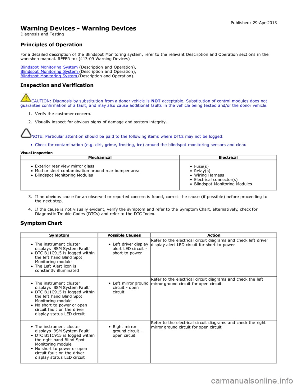
Symptom Possible Causes Action
The instrument cluster
displays 'BSM System Fault'
DTC B11C915 is logged within
the left hand Blind Spot
Monitoring module
The Left Alert icon is
constantly illuminated
Left driver display
alert LED circuit -
short to power Refer to the electrical circuit diagrams and check left driver
display alert LED circuit for short to power
The instrument cluster
displays 'BSM System Fault'
DTC B11C915 is logged within
the left hand Blind Spot
Monitoring module
No short to power or open
circuit fault on the driver
display status LED circuit
Left mirror ground
circuit - open
circuit Refer to the electrical circuit diagrams and check the left
mirror ground circuit for open circuit
The instrument cluster
displays 'BSM System Fault'
DTC B11C915 is logged within
the right hand Blind Spot
Monitoring module
No short to power or open
circuit fault on the driver
display status LED circuit
Right mirror
ground circuit -
open circuit Refer to the electrical circuit diagrams and check the right
mirror ground circuit for open circuit
Page 1850 of 3039
Parking Aid - Parking Aid
Diagnosis and Testing
Principles of Operation Published: 24-Feb-2014
For a detailed description of the parking aid system, characteristics and limitations refer to the relevant description and
operation section in the workshop manual.
REFER to: Parking Aid (413-13 Parking Aid, Description and Operation).
Parking Aid System On-Board Self-Test
As part of the strategy of the system if any DTCs are detected, a long high-pitched tone approx 3 seconds will sound and the
parking aid switch (where fitted) indicator LED will flash 6 times at ignition on
If a fault is present when the parking aid system is activated then the parking aid switch (where fitted) status LED will
flash 6 times indicating an issue with front or rear parking aid sensors, wiring switch, parking aid control module or hard
wired sounders
The rear parking aid sounder/rear audio system will emit an error tone for approx 3 seconds at ignition on if a fault is
detected with the front or rear sensors, the switch, or if there is a controller area network (CAN) bus error
(Only applicable to vehicles fitted with front parking aid and a hard wired rear parking aid sounder). If there is a fault
with the rear parking aid sounder the error tone will come from the front parking aid sounder unit (integral with the
instrument cluster)
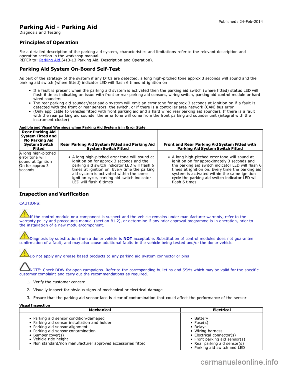
Audible and Visual Warnings when Parking Aid System is in Error State
Rear Parking Aid
System Fitted and
No Parking Aid
System Switch
Fitted
Rear Parking Aid System Fitted and Parking Aid System Switch Fitted
Front and Rear Parking Aid System Fitted with Parking Aid System Switch Fitted A long high-pitched
error tone will
sound at Ignition
On for approx 3
seconds
A long high-pitched error tone will sound at
ignition on for approx 3 seconds and the
parking aid switch indicator LED will flash 6
times at ignition on. Every time the parking
aid system is activated within the same
ignition cycle, parking aid switch indicator
LED will flash 6 times
A long high-pitched error tone will sound at
ignition on for approximately 3 seconds and
the parking aid switch indicator LED will flash 6
times at ignition on. Every time the parking aid
system is activated within the same ignition
cycle the parking aid switch indicator LED will
flash 6 times Inspection and Verification
CAUTIONS:
If the control module or a component is suspect and the vehicle remains under manufacturer warranty, refer to the
warranty policy and procedures manual (section B1.2), or determine if any prior approval programme is in operation, prior to
the installation of a new module/component.
Diagnosis by substitution from a donor vehicle is NOT acceptable. Substitution of control modules does not guarantee
confirmation of a fault, and may also cause additional faults in the vehicle being tested and/or the donor vehicle
Do not apply any grease based products to any parking aid system connector or pins
NOTE: Check DDW for open campaigns. Refer to the corresponding bulletins and SSMs which may be valid for the specific
customer complaint and carry out the recommendations as required.
1. Verify the customer concern
2. Visually inspect for obvious signs of mechanical or electrical damage
3. Ensure that the parking aid sensor face is clear of contamination that could affect the performance of the sensor
Visual Inspection
Mechanical Electrical
Parking aid sensor condition/damaged
Parking aid sensor installation and holder
Parking aid sensor alignment
Parking aid sensor contamination
Bumper cover(s)
Vehicle ride height
Non standard/non manufacturer approved accessories fitted
Battery
Fuse(s)
Relays
Wiring harness
Electrical connector(s)
Front parking aid sensor(s)
Rear parking aid sensor(s)
Parking aid switch and LED
Page 1866 of 3039
Published: 07-Aug-2014
Battery and Charging System - General Information - Battery Care
Requirements
Description and Operation
1. INTRODUCTION
This document defines the requirements for care and maintenance of batteries, and the standard of battery care at dealers and
retailers for new vehicles.
This applies to all types of 12 Volt Lead Acid Batteries used in Jaguar and Land Rover vehicles whether they are conventional
flooded technology or Absorbed Glass Mat (AGM – also known as Valve Regulated Lead Acid (VRLA)) technology and also
applies to both Primary, Secondary and Auxiliary Batteries. AGM batteries offer improved resistance to cycling as seen in stop
start applications.
In order to prevent damage to the battery and ensure a satisfactory service life, all processes detailed within this document
must be rigorously adhered to.
It is equally important therefore to note the following key points:
All new vehicles leave the factory with either a transit relay installed and/or have a transit mode programmed into the
vehicle control modules. The transit relay must be removed and the transit mode disabled (where applicable) using an
approved diagnostic system, NOT MORE THAN 72 HOURS before the customer takes delivery.
The battery can be discharged by the following mechanisms:
- Self Discharge: - A lead acid battery will very slowly discharge itself due to its own internal chemical processes
whether it is connected to a vehicle or not.
- Quiescent Discharge: - The vehicle electrical systems when connected to the battery will draw charge from the
battery.
12 Volt Lead Acid Batteries rely on internal chemical processes to create a voltage and deliver current. These processes and
the internal chemical structure of the battery can be damaged if the battery is allowed to discharge over a number of weeks /
months, or is left in a discharged state for a lengthy time period.
On vehicles with conventional ignition keys, these must not be left in the ignition lock barrel when the transit relay
has been removed, otherwise quiescent current will increase and the battery will discharge more rapidly.
For keyless vehicles, the Smart Key must be stored at least 5m (16 ft) away from the vehicle when the vehicle is
parked or stored.
AGM Batteries are fully sealed and cannot have the electrolyte level topped up.
NOTE: Dealers and retailers involved in the storage / handling of vehicles and replacement batteries have a responsibility
to ensure that only a fully charged battery may be processed through the distribution selling chain.
2. GENERAL RULES FOR BATTERY CARE
2.1 Dealer Demonstration Vehicles
Vehicles used as dealer demonstrator(s), in a showroom, must be connected to a JLR approved showroom conditioner capable
of delivering 50 Amps. This will prevent the battery from being damaged.
2.2 Software Reflash, SDD work or Ignition On related workshop activities
Due to the high electrical current demand and high depth of discharge that can occur during vehicle software re-flash activities,
SDD work or ignition on (power mode 6) related work in the workshop, vehicles that are undergoing such activities MUST have a
JLR approved power supply capable of delivering 50 Amps or more.
2.3 Extended Vehicle Rework
For any extended vehicle rework that results in consuming vehicle power, either the battery should be disconnected or a JLR
approved power supply connected.
2.4 Jump Starting New vehicles before they have been delivered to the customer
It is the dealer / retailers responsibility to make sure the battery is not allowed to discharge by following the
instructions and processes defined in this manual.
However, if circumstances dictate that a new vehicle must be jump started due to a discharged battery whilst the
vehicle is in the dealer / retailers care, the battery on this vehicle must be replaced with a new one prior to delivery
to the customer at the dealer / retailers liability.
The vehicle should also undergo investigation as to why the battery became discharged.
Do not connect the jump starting cable to the negative (-) terminal of the battery. Always connect to the recommended
earth point. As defined in the owners handbook or service documentation for that vehicle. 2.5 AGM Batteries
AGM batteries must not be charged above 14.8 Volts. Doing so will damage them.
AGM Batteries must be tested with a capable battery tester as detailed in the Equipment section (Section 5) of this
Page 1867 of 3039
procedure.
NOTE: Under no circumstances should the battery be disconnected with the engine running because under these
conditions the generator can give a very high output voltage. This high transient voltage will damage the electronic
components in the vehicle. Loose or incomplete battery connections may also cause high transient voltage.
3. HEALTH AND SAFETY PRECAUTIONS
WARNINGS:
BATTERY CELLS CONTAIN SULPHURIC ACID AND EXPLOSIVE MIXTURES OF HYDROGEN AND OXYGEN GASES. IT IS
THEREFORE ESSENTIAL THAT THE FOLLOWING SAFETY PRECAUTIONS ARE OBSERVED.
Batteries emit highly explosive hydrogen at all times, particularly during charging. To prevent any potential form of
ignition occurring when working in the vicinity of a battery:
Do not smoke when working near batteries.
Avoid sparks, short circuits or other sources of ignition in the battery vicinity.
Switch off current before making or breaking electrical connections.
Ensure battery charging area is well ventilated.
Ensure the charger is switched off when: a) connecting to a battery; b) disconnecting from the battery.
Always disconnect the ground cable from the battery terminal first and reconnect it last.
Batteries contain poisonous and highly corrosive acid. To prevent personal injury, or damage to clothing or the vehicle,
the following working practices should be followed when topping up, checking electrolyte specific gravity, removal, refitting or
carrying batteries:
Always wear suitable protective clothing (an apron or similar), safety glasses, a face mask and suitable gloves.
If acid is spilled or splashed onto clothing or the body, it must be neutralized immediately and then rinsed with clean
water. A solution of baking soda or household ammonia and water may be used as a neutralizer.
In the event of contact with the skin, drench the affected area with water. In the case of contact with the eyes, bathe
the affected area with cool clean water for approximately 15 minutes and seek urgent medical attention.
If battery acid is spilled or splashed on any surface of a vehicle, it should be neutralized and rinsed with clean water.
Heat is generated when acid is mixed with water. If it becomes necessary to prepare electrolyte of a desired specific
gravity, SLOWLY pour the concentrated acid into water (not water into acid), adding small amounts of acid while
stirring. Allow the electrolyte to cool if noticeable heat develops. With the exception of lead or lead-lined containers,
always use non-metallic receptacles or funnels. Do not store acid in excessively warm locations or in direct sunlight.
Due to their hazardous contents, the disposal of batteries is strictly controlled. When a battery is scrapped, ensure it is
disposed of safely, complying with local environmental regulations. If in doubt, contact your local authority for advice on
disposal facilities.
4. BATTERY CARE REQUIREMENTS
4.1 RECEIPT OF A NEW VEHICLE
Within 24 hours of receipt of a new vehicle, a battery condition check must be carried out in accordance with the battery test
process utilizing a JLR approved tester as outlined in the Equipment section (Section 5) of this procedure.
NOTE: The Midtronics code from the tester must be recorded on the form.
Any actions must be carried out in accordance with the table shown in the Determining Battery Condition section (Section 6)
of this procedure. The details must be recorded on the New Vehicle Storage Form which is part of the new vehicle storage
document.
For additional information, refer to: New Vehicle Storage Form (100-11 Vehicle Transportation Aids and Vehicle Storage, Description and Operation).
4.2 NEW VEHICLE STORAGE
If the vehicle is to be stored the transit relays MUST be refitted and / or the vehicle put into transport mode.
Transit relay removal / vehicle placed in normal mode should only be completed a maximum of 72 hours prior to handover to
customer
For vehicles without either a transit mode or transit relay the battery negative cable must be DISCONNECTED from the battery.
The battery must be tested and/or re-charged every 30 days and MUST be re-charged after every 90 day period.
NOTE: The Midtronics code from the tester must be recorded on the form. www.JagDocs.com