Ejb relay JAGUAR XFR 2010 1.G Workshop Manual
[x] Cancel search | Manufacturer: JAGUAR, Model Year: 2010, Model line: XFR, Model: JAGUAR XFR 2010 1.GPages: 3039, PDF Size: 58.49 MB
Page 1114 of 3039
14 Radiator 15 Auxiliary radiator 16 Connection with supercharger cooling system
System Operation
When the engine is running, the coolant is circulated around the engine cooling system by the coolant pump. From the coolant
pump, coolant flows through the cylinder heads and the engine oil cooler into the cylinder block and the heater manifold.
In the cylinder block, the coolant flows forwards to the outlet tube. When the coolant is cold, the thermostat is closed and the
coolant flows direct from the outlet tube back to the coolant pump. Once the coolant reaches operating temperature the
thermostat begins to open, to control system temperature, and coolant flows from the outlet tube to the coolant pump via the
radiator and, on SC (supercharger) vehicles, the auxiliary radiator. When the thermostat is open, the coolant flow through the
radiator(s) also generates a coolant flow through the transmission fluid cooler.
From the heater manifold the coolant flows through the electronic throttle and the heater core, in parallel circuits that are
unaffected by the position of the thermostat. From the electronic throttle, the coolant merges with bleed coolant from the
coolant pump and the outlet tube and flows to the expansion tank. From the heater core, the coolant flows back to the inlet of
the coolant pump.
Expansion and contraction of the coolant is accommodated by an air space in the expansion tank and the compliance of the
flexible hoses.
If the coolant level in the expansion tank decreases below a predetermined value, the level sensor connects a ground to the
instrument cluster, which activates the appropriate warning. For additional information, refer to 413-01 Instrument Cluster.
The cooling fan is operated by a fan control module integrated into the cooling fan motor. The fan control module regulates the
voltage, and thus speed, of the cooling fan motor in response to a PWM (pulse width modulation) signal from the ECM (engine
control module).
The cooling fan receives a battery feed and an ignition feed from the EJB (engine junction box). The ignition feed is supplied
from the main relay in the EJB, which is controlled by the ECM.
The ECM calculates the required fan speed from the engine temperature, A/C (air conditioning) system pressure and transmission fluid temperature. Under hot operating conditions, the fan may continue to operate for 4 minutes after the engine
has been switched off.
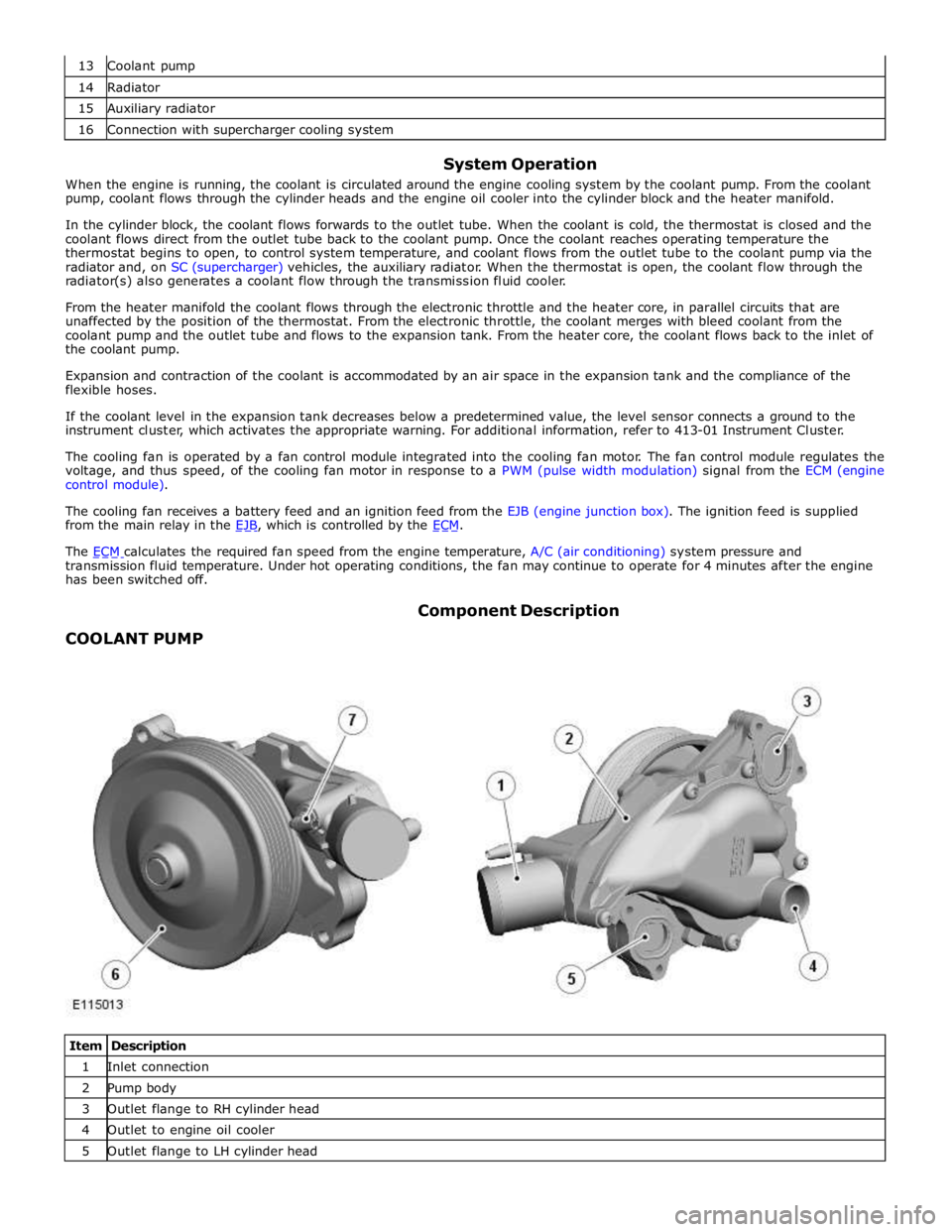
COOLANT PUMP Component Description
Item Description 1 Inlet connection 2 Pump body 3 Outlet flange to RH cylinder head 4 Outlet to engine oil cooler 5 Outlet flange to LH cylinder head
Page 1261 of 3039
Published: 11-May-2011
Starting System - V8 5.0L Petrol/V8 S/C 5.0L Petrol - Starting System - System Operation and Component Description
Description and Operation
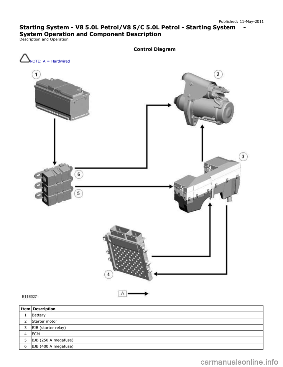
Control Diagram
NOTE: A = Hardwired
Item Description 1 Battery 2 Starter motor 3 EJB (starter relay) 4 ECM 5 BJB (250 A megafuse) 6 BJB (400 A megafuse)
Page 1262 of 3039

When the ECM receives a crank request, it energizes the starter relay in the EJB (engine junction box). The energized starter relay supplies 12 V power (fed via the 250 A megafuse in the BJB (battery junction box)) to energize the pull-in coil of the
starter solenoid. Once activated, the pull-in coil engages the solenoid plunger, which engages the pinion with the ring gear.
The plunger then closes the solenoid circuit, feeding power from the 400 A megafuse in the BJB to the starter motor.
Page 1273 of 3039
Published: 11-May-2011
Engine Ignition - V8 5.0L Petrol/V8 S/C 5.0L Petrol - Engine Ignition - System Operation and Component Description
Description and Operation
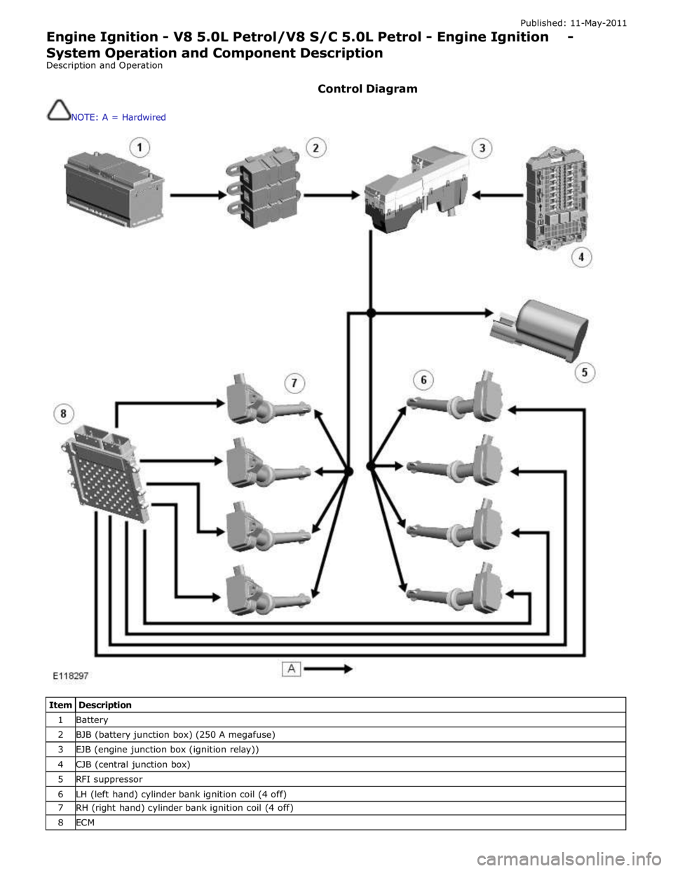
Control Diagram
NOTE: A = Hardwired
Item Description 1 Battery 2 BJB (battery junction box) (250 A megafuse) 3 EJB (engine junction box (ignition relay)) 4 CJB (central junction box) 5 RFI suppressor 6 LH (left hand) cylinder bank ignition coil (4 off) 7 RH (right hand) cylinder bank ignition coil (4 off) 8 ECM
Page 1274 of 3039
GENERAL System Operation
The ignition coils are supplied with electrical power from the battery via a 250 A megafuse in the BJB (battery junction box)
and the ignition relay in the EJB (engine junction box). The control signal for the ignition relay is supplied by the CJB (central
junction box).
The ECM (engine control module) sends a separate signal to each ignition coil to trigger the power stage switching. The ECM calculates the dwell time from the battery voltage and engine speed, to ensure a constant energy level is produced in the
secondary coil each time the power stage is switched. This ensures sufficient spark energy is available without excessive
primary current flow, which avoids overheating and damage to the ignition coils.
The ECM calculates the ignition timing for individual cylinders from: Engine speed
Camshaft position
Engine load
Engine temperature
The knock control function
The shift control function
The idle speed control function.
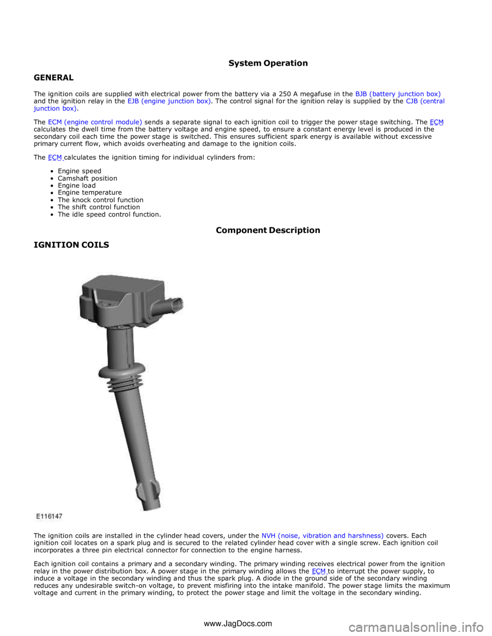
IGNITION COILS Component Description
The ignition coils are installed in the cylinder head covers, under the NVH (noise, vibration and harshness) covers. Each
ignition coil locates on a spark plug and is secured to the related cylinder head cover with a single screw. Each ignition coil
incorporates a three pin electrical connector for connection to the engine harness.
Each ignition coil contains a primary and a secondary winding. The primary winding receives electrical power from the ignition
relay in the power distribution box. A power stage in the primary winding allows the ECM to interrupt the power supply, to induce a voltage in the secondary winding and thus the spark plug. A diode in the ground side of the secondary winding
reduces any undesirable switch-on voltage, to prevent misfiring into the intake manifold. The power stage limits the maximum
voltage and current in the primary winding, to protect the power stage and limit the voltage in the secondary winding. www.JagDocs.com
Page 1288 of 3039

Published: 11-May-2011
Intake Air Distribution and Filtering - V8 S/C 5.0L Petrol - Intake Air
Distribution and Filtering - System Operation and Component Description
Description and Operation
Control Diagram
NOTE: A = Hardwired
Item Description 1 Battery 2 BJB (battery junction box) (250 A megafuse) 3 EJB (engine junction box) (EMS high current relay) 4 Tuning valve 5 ECM (engine control module)
Page 1711 of 3039
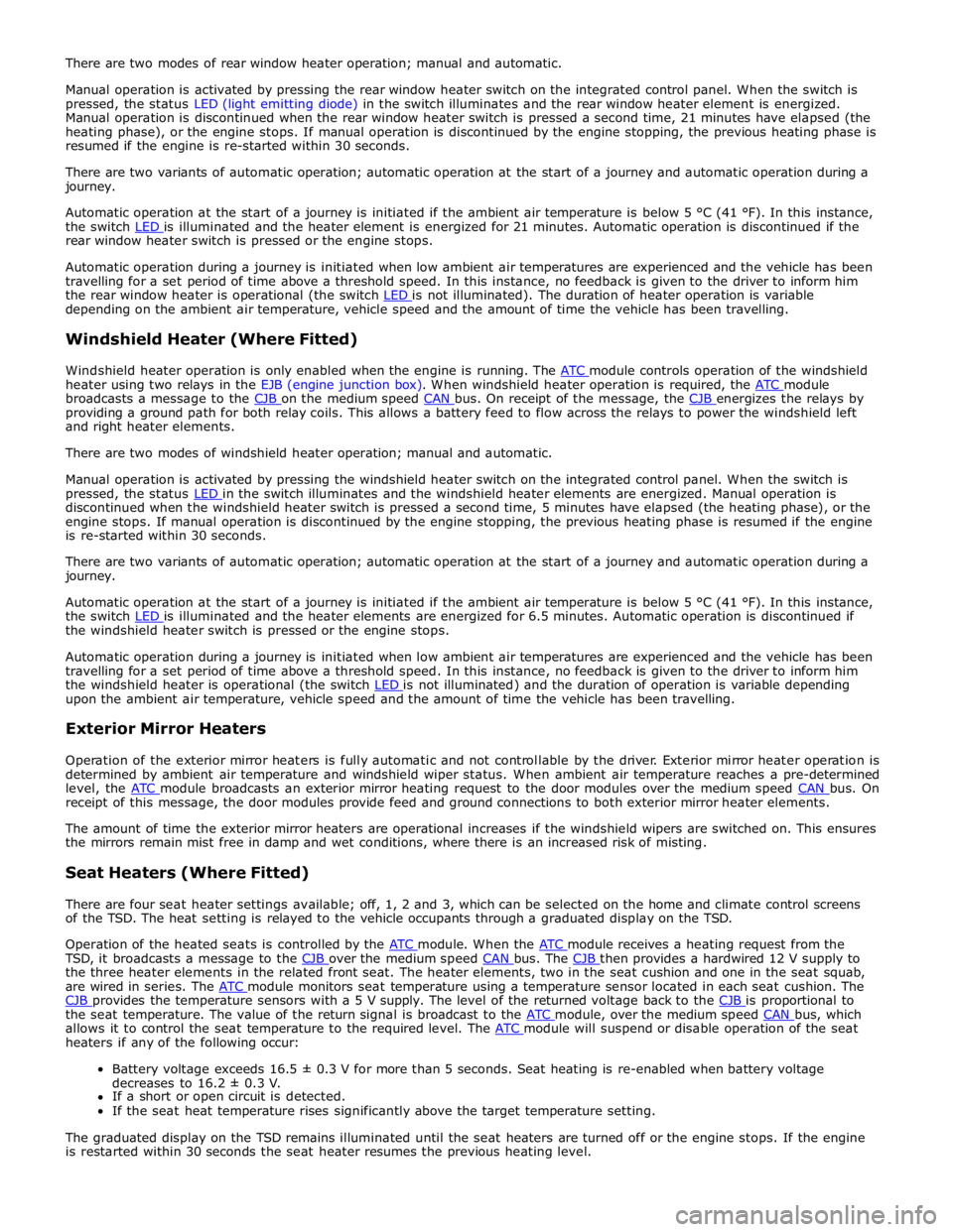
rear window heater switch is pressed or the engine stops.
Automatic operation during a journey is initiated when low ambient air temperatures are experienced and the vehicle has been
travelling for a set period of time above a threshold speed. In this instance, no feedback is given to the driver to inform him
the rear window heater is operational (the switch LED is not illuminated). The duration of heater operation is variable depending on the ambient air temperature, vehicle speed and the amount of time the vehicle has been travelling.
Windshield Heater (Where Fitted)
Windshield heater operation is only enabled when the engine is running. The ATC module controls operation of the windshield heater using two relays in the EJB (engine junction box). When windshield heater operation is required, the ATC module broadcasts a message to the CJB on the medium speed CAN bus. On receipt of the message, the CJB energizes the relays by providing a ground path for both relay coils. This allows a battery feed to flow across the relays to power the windshield left
and right heater elements.
There are two modes of windshield heater operation; manual and automatic.
Manual operation is activated by pressing the windshield heater switch on the integrated control panel. When the switch is
pressed, the status LED in the switch illuminates and the windshield heater elements are energized. Manual operation is discontinued when the windshield heater switch is pressed a second time, 5 minutes have elapsed (the heating phase), or the
engine stops. If manual operation is discontinued by the engine stopping, the previous heating phase is resumed if the engine
is re-started within 30 seconds.
There are two variants of automatic operation; automatic operation at the start of a journey and automatic operation during a
journey.
Automatic operation at the start of a journey is initiated if the ambient air temperature is below 5 °C (41 °F). In this instance,
the switch LED is illuminated and the heater elements are energized for 6.5 minutes. Automatic operation is discontinued if the windshield heater switch is pressed or the engine stops.
Automatic operation during a journey is initiated when low ambient air temperatures are experienced and the vehicle has been
travelling for a set period of time above a threshold speed. In this instance, no feedback is given to the driver to inform him
the windshield heater is operational (the switch LED is not illuminated) and the duration of operation is variable depending upon the ambient air temperature, vehicle speed and the amount of time the vehicle has been travelling.
Exterior Mirror Heaters
Operation of the exterior mirror heaters is fully automatic and not controllable by the driver. Exterior mirror heater operation is
determined by ambient air temperature and windshield wiper status. When ambient air temperature reaches a pre-determined
level, the ATC module broadcasts an exterior mirror heating request to the door modules over the medium speed CAN bus. On receipt of this message, the door modules provide feed and ground connections to both exterior mirror heater elements.
The amount of time the exterior mirror heaters are operational increases if the windshield wipers are switched on. This ensures
the mirrors remain mist free in damp and wet conditions, where there is an increased risk of misting.
Seat Heaters (Where Fitted)
There are four seat heater settings available; off, 1, 2 and 3, which can be selected on the home and climate control screens
of the TSD. The heat setting is relayed to the vehicle occupants through a graduated display on the TSD.
Operation of the heated seats is controlled by the ATC module. When the ATC module receives a heating request from the TSD, it broadcasts a message to the CJB over the medium speed CAN bus. The CJB then provides a hardwired 12 V supply to the three heater elements in the related front seat. The heater elements, two in the seat cushion and one in the seat squab,
are wired in series. The ATC module monitors seat temperature using a temperature sensor located in each seat cushion. The CJB provides the temperature sensors with a 5 V supply. The level of the returned voltage back to the CJB is proportional to the seat temperature. The value of the return signal is broadcast to the ATC module, over the medium speed CAN bus, which allows it to control the seat temperature to the required level. The ATC module will suspend or disable operation of the seat heaters if any of the following occur:
Battery voltage exceeds 16.5 ± 0.3 V for more than 5 seconds. Seat heating is re-enabled when battery voltage
decreases to 16.2 ± 0.3 V.
If a short or open circuit is detected.
If the seat heat temperature rises significantly above the target temperature setting.
The graduated display on the TSD remains illuminated until the seat heaters are turned off or the engine stops. If the engine
is restarted within 30 seconds the seat heater resumes the previous heating level.
Page 1877 of 3039
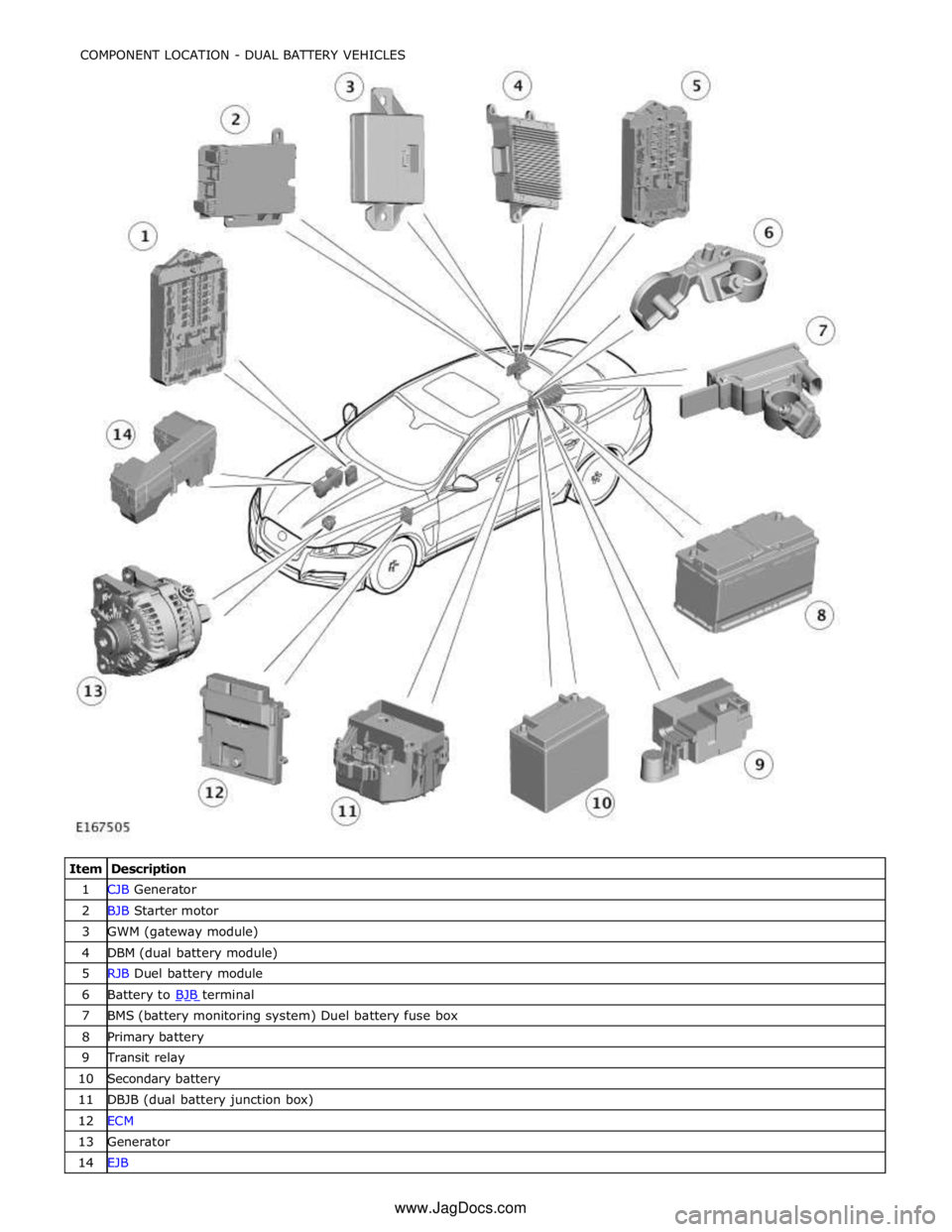
1 CJB Generator 2 BJB Starter motor 3 GWM (gateway module) 4 DBM (dual battery module) 5 RJB Duel battery module 6 Battery to BJB terminal 7 BMS (battery monitoring system) Duel battery fuse box 8 Primary battery 9 Transit relay 10 Secondary battery 11 DBJB (dual battery junction box) 12 ECM 13 Generator 14 EJB COMPONENT LOCATION - DUAL BATTERY VEHICLES
www.JagDocs.com
Page 1878 of 3039
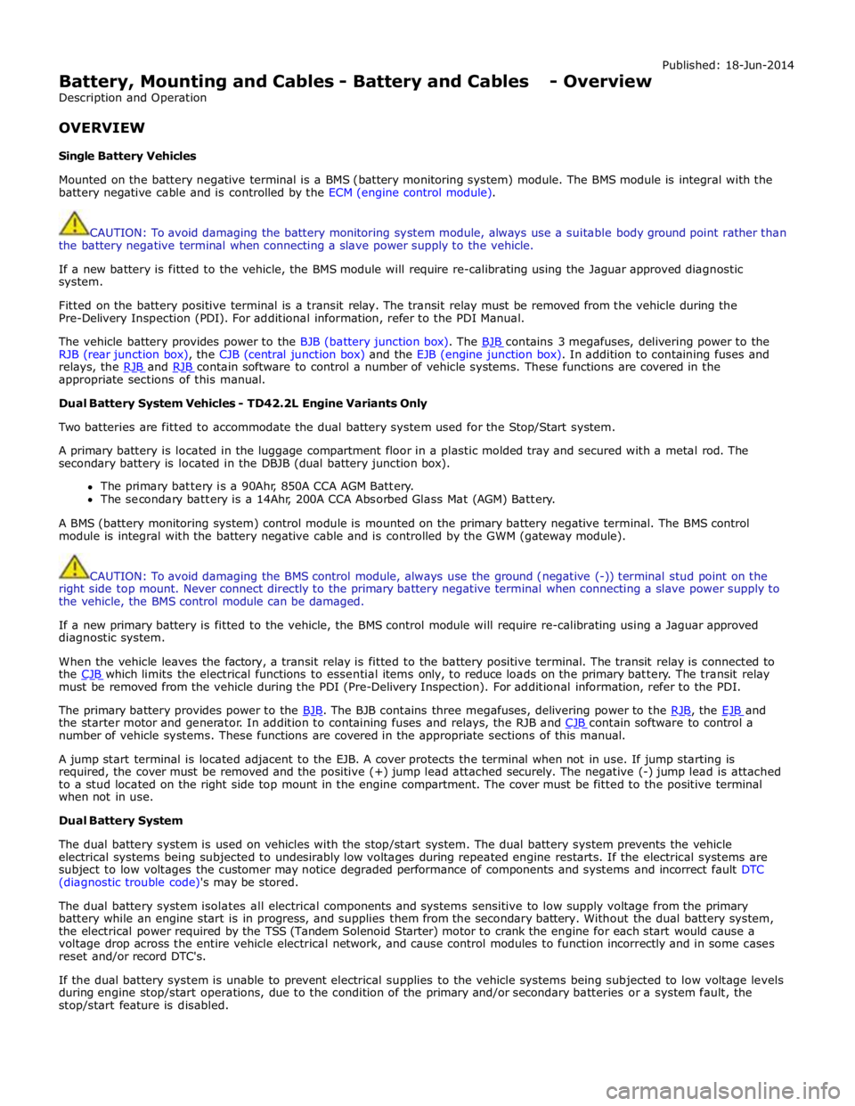
Battery, Mounting and Cables - Battery and Cables - Overview
Description and Operation
OVERVIEW
Single Battery Vehicles Published: 18-Jun-2014
Mounted on the battery negative terminal is a BMS (battery monitoring system) module. The BMS module is integral with the
battery negative cable and is controlled by the ECM (engine control module).
CAUTION: To avoid damaging the battery monitoring system module, always use a suitable body ground point rather than
the battery negative terminal when connecting a slave power supply to the vehicle.
If a new battery is fitted to the vehicle, the BMS module will require re-calibrating using the Jaguar approved diagnostic
system.
Fitted on the battery positive terminal is a transit relay. The transit relay must be removed from the vehicle during the
Pre-Delivery Inspection (PDI). For additional information, refer to the PDI Manual.
The vehicle battery provides power to the BJB (battery junction box). The BJB contains 3 megafuses, delivering power to the RJB (rear junction box), the CJB (central junction box) and the EJB (engine junction box). In addition to containing fuses and
relays, the RJB and RJB contain software to control a number of vehicle systems. These functions are covered in the appropriate sections of this manual.
Dual Battery System Vehicles - TD42.2L Engine Variants Only
Two batteries are fitted to accommodate the dual battery system used for the Stop/Start system.
A primary battery is located in the luggage compartment floor in a plastic molded tray and secured with a metal rod. The
secondary battery is located in the DBJB (dual battery junction box).
The primary battery is a 90Ahr, 850A CCA AGM Battery.
The secondary battery is a 14Ahr, 200A CCA Absorbed Glass Mat (AGM) Battery.
A BMS (battery monitoring system) control module is mounted on the primary battery negative terminal. The BMS control
module is integral with the battery negative cable and is controlled by the GWM (gateway module).
CAUTION: To avoid damaging the BMS control module, always use the ground (negative (-)) terminal stud point on the
right side top mount. Never connect directly to the primary battery negative terminal when connecting a slave power supply to
the vehicle, the BMS control module can be damaged.
If a new primary battery is fitted to the vehicle, the BMS control module will require re-calibrating using a Jaguar approved
diagnostic system.
When the vehicle leaves the factory, a transit relay is fitted to the battery positive terminal. The transit relay is connected to
the CJB which limits the electrical functions to essential items only, to reduce loads on the primary battery. The transit relay must be removed from the vehicle during the PDI (Pre-Delivery Inspection). For additional information, refer to the PDI.
The primary battery provides power to the BJB. The BJB contains three megafuses, delivering power to the RJB, the EJB and the starter motor and generator. In addition to containing fuses and relays, the RJB and CJB contain software to control a number of vehicle systems. These functions are covered in the appropriate sections of this manual.
A jump start terminal is located adjacent to the EJB. A cover protects the terminal when not in use. If jump starting is
required, the cover must be removed and the positive (+) jump lead attached securely. The negative (-) jump lead is attached
to a stud located on the right side top mount in the engine compartment. The cover must be fitted to the positive terminal
when not in use.
Dual Battery System
The dual battery system is used on vehicles with the stop/start system. The dual battery system prevents the vehicle
electrical systems being subjected to undesirably low voltages during repeated engine restarts. If the electrical systems are
subject to low voltages the customer may notice degraded performance of components and systems and incorrect fault DTC
(diagnostic trouble code)'s may be stored.
The dual battery system isolates all electrical components and systems sensitive to low supply voltage from the primary
battery while an engine start is in progress, and supplies them from the secondary battery. Without the dual battery system,
the electrical power required by the TSS (Tandem Solenoid Starter) motor to crank the engine for each start would cause a
voltage drop across the entire vehicle electrical network, and cause control modules to function incorrectly and in some cases
reset and/or record DTC's.
If the dual battery system is unable to prevent electrical supplies to the vehicle systems being subjected to low voltage levels
during engine stop/start operations, due to the condition of the primary and/or secondary batteries or a system fault, the
stop/start feature is disabled.
Page 2028 of 3039
resistors. The returned signal voltage is detected by the instrument cluster which outputs a message on the medium speed
CAN bus to the CJB to activate the headlamps. The reference voltage to the auto headlamp exit delay switch is routed through 4 resistors which is detected by the instrument cluster which outputs a message on the medium speed CAN bus to the CJB that auto headlamp or exit delay has not been selected.
AUTOLAMPS - When the lighting control switch is in the auto headlamp position, the reference voltage flows through 4 of the
resistors. The returned signal voltage is detected by the instrument cluster which outputs a message on the medium speed
CAN bus to the CJB to activate the autolamp function. The reference voltage to the autolamp exit delay switch is routed through 4 resistors which is detected by the instrument cluster which outputs a message on the medium speed CAN bus to the CJB that auto headlamp has been selected.
AUXILIARY LIGHTING SWITCH
Headlamp Leveling Rotary Thumbwheel (Halogen headlamps only)
A power supply is passed to the headlamp leveling thumbwheel from the ignition relay in the EJB. Depending on the position of the thumbwheel, the voltage passes through 1, 2 or 3 resistors connected in series. The voltage through the resistors is
passed to the headlamp leveling motor controller in each headlamp. The received voltage is determined as a request for the
appropriate level position and the controller powers the headlamp level motors to the applicable position for each headlamp.
Rear Fog Lamp Switch
The instrument cluster supplies a reference voltage and return to the rear fog lamp switch. The fog lamp switch is a
non-latching, momentary switch.
When the fog lamp switch is off the reference voltage is passed through a 1Kohm resistor. The voltage through the resistor is
returned to the instrument cluster that determines that no request for fog lamp operation has been made.
When the driver presses the fog lamp switch, the reference voltage is passed through a 330 ohm resistor. The change is return
voltage is sensed by the instrument cluster which determines fog lamp operation has been requested. The instrument cluster
transmits a medium speed CAN bus signal to the RJB providing the lighting control switch is in the correct position. The RJB reacts to the message and provides a power supply to the 3 LED (light emitting diode)'s in each rear fog lamp. A fog lamp
warning lamp in the instrument cluster will also be illuminated when the fog lamps are operating.
The RJB will only activate the rear fog lamps if the headlamps are selected on or are active with auto headlamp activation. When the headlamps are turned off the fog lamps are also turned off. When the headlamps are next switched on, the fog
lamps will not be activated until the driver requests fog lamp operation.
NOTE: The fog lamps do operate when DRL (daytime running lamps) are active.
HEADLAMP LEVELING
Manual Headlamp Leveling - Halogen headlamps only
A power supply is passed to the headlamp leveling motor in each headlamp from the ignition relay in the EJB. When a signal voltage is received from the headlamp leveling rotary thumbwheel, the headlamp leveling motor controller in each headlamp
uses the power supply to operate the motors and move the headlamp to the requested position.
Static Dynamic Headlamp Leveling - Xenon headlamps only
The headlamp leveling module receives a power supply from the ignition relay in the EJB. The same power supply is also supplied to the headlamp leveling motor in each headlamp assembly. The front and rear height sensors are connected to the
headlamp leveling module and receive a power and ground from the module. Each sensor has a signal line to the headlamp
leveling module to return height information to the module. The module uses the height signals from the sensors to calculate
the vehicle attitude and supplies a signal to each motor to power the headlamp to the required position.
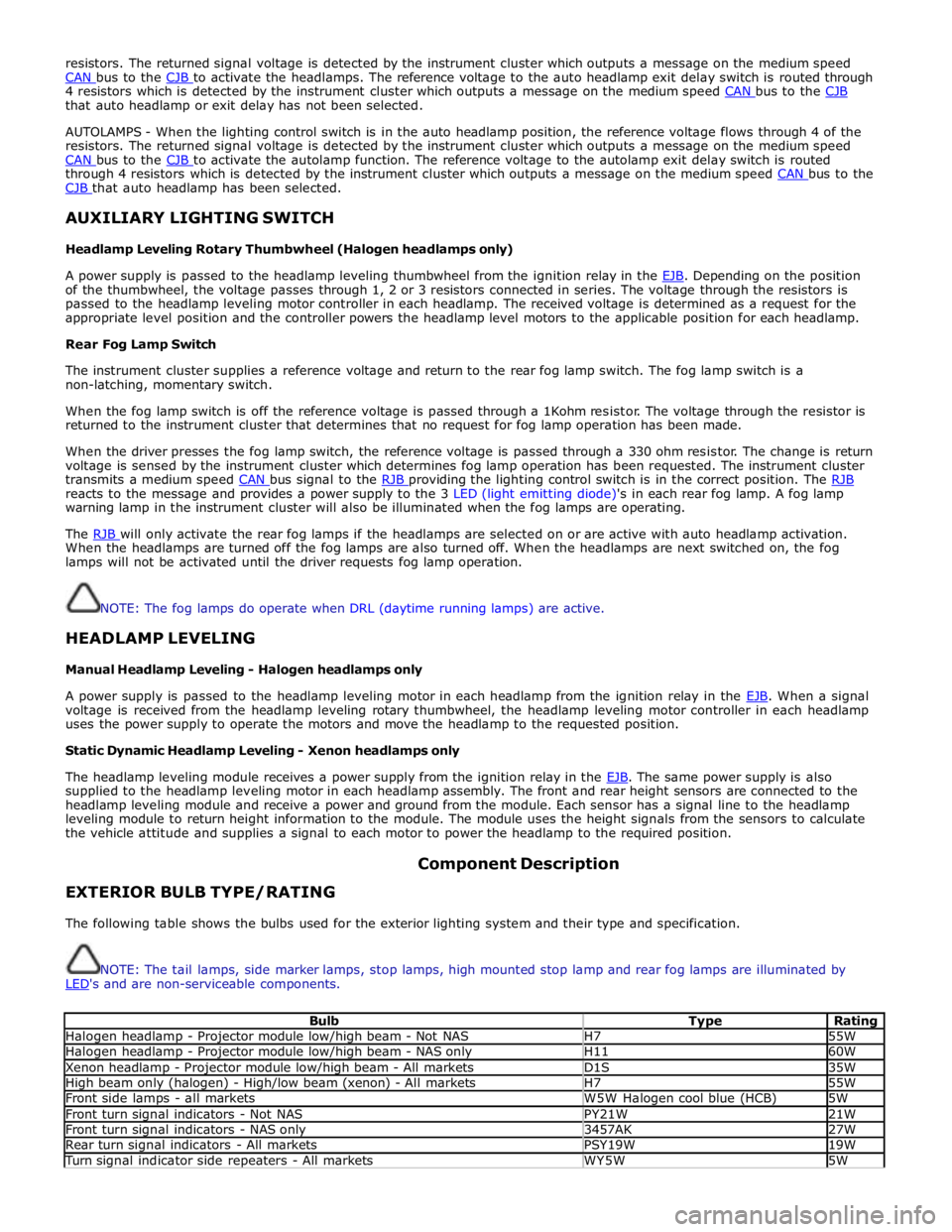
EXTERIOR BULB TYPE/RATING Component Description
The following table shows the bulbs used for the exterior lighting system and their type and specification.
NOTE: The tail lamps, side marker lamps, stop lamps, high mounted stop lamp and rear fog lamps are illuminated by
LED's and are non-serviceable components.
Bulb Type Rating Halogen headlamp - Projector module low/high beam - Not NAS H7 55W Halogen headlamp - Projector module low/high beam - NAS only H11 60W Xenon headlamp - Projector module low/high beam - All markets D1S 35W High beam only (halogen) - High/low beam (xenon) - All markets H7 55W Front side lamps - all markets W5W Halogen cool blue (HCB) 5W Front turn signal indicators - Not NAS PY21W 21W Front turn signal indicators - NAS only 3457AK 27W Rear turn signal indicators - All markets PSY19W 19W Turn signal indicator side repeaters - All markets WY5W 5W