clock setting JAGUAR XFR 2010 1.G Workshop Manual
[x] Cancel search | Manufacturer: JAGUAR, Model Year: 2010, Model line: XFR, Model: JAGUAR XFR 2010 1.GPages: 3039, PDF Size: 58.49 MB
Page 1641 of 3039
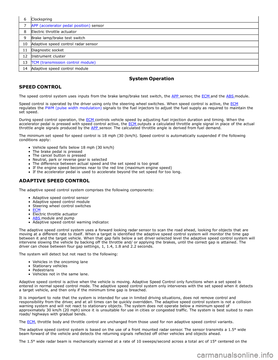
6 Clockspring 7 APP (accelerator pedal position) sensor 8 Electric throttle actuator 9 Brake lamp/brake test switch 10 Adaptive speed control radar sensor 11 Diagnostic socket 12 Instrument cluster 13 TCM (transmission control module) 14 Adaptive speed control module
SPEED CONTROL System Operation
The speed control system uses inputs from the brake lamp/brake test switch, the APP sensor, the ECM and the ABS module.
Speed control is operated by the driver using only the steering wheel switches. When speed control is active, the ECM regulates the PWM (pulse width modulation) signals to the fuel injectors to adjust the fuel supply as required to maintain the
set speed.
During speed control operation, the ECM controls vehicle speed by adjusting fuel injection duration and timing. When the accelerator pedal is pressed with speed control active, the ECM outputs a calculated throttle angle signal in place of the actual throttle angle signals produced by the APP sensor. The calculated throttle angle is derived from fuel demand.
The minimum set speed for speed control is 18 mph (30 (km/h). Speed control is automatically suspended if the following
conditions apply:
Vehicle speed falls below 18 mph (30 km/h)
The brake pedal is pressed
The cancel button is pressed
Neutral, park or reverse gear is selected
The difference between actual speed and the set speed is too great
If the engine speed becomes near to the red line (maximum engine speed)
If the accelerator pedal is used to accelerate beyond the set speed for too long.
ADAPTIVE SPEED CONTROL
The adaptive speed control system comprises the following components:
Adaptive speed control sensor
Adaptive speed control module
Steering wheel control switches
ECM
Electric throttle actuator
ABS module and pump Adaptive speed control warning indicator.
The adaptive speed control system uses a forward looking radar sensor to scan the road ahead, looking for objects that are
moving at a different rate to itself. When a target is identified the adaptive speed control system will monitor the time gap
between it and the target vehicle. When that gap falls below a set driver selected level the adaptive speed control system will
intervene slowing the vehicle by backing off the throttle and/ or applying the brakes, until the correct gap is attained. The
driver can chose between four gap settings, 1, 1.4, 1.8 and 2.2 seconds.
The system will detect but not react to the following:
Vehicles in the oncoming lane
Stationary vehicles
Pedestrians
Vehicles not in the same lane.
Adaptive speed control is active when the vehicle is moving. Adaptive Speed Control only functions when a set speed is
entered in normal speed control mode. The adaptive speed control system only intervenes with the set speed when it detects
a target vehicle, and then only if the minimum time gap is breached.
It is important to note that the system is intended for use in limited driving situations, does not remove control and
responsibility from the driver, and at all times can be quickly overridden. The adaptive speed control system is not a collision
warning system and will not react to stationary objects. The system does not operate below a minimum speed of
approximately 30 km/h (20 mph) since it is unsuitable for use in cities or congested traffic. The system is best suited to main
roads/ highways with gradual bends.
The ECM, throttle body and throttle control are unchanged from those used for non adaptive speed control variants.
The adaptive speed control system is based on the use of a front mounted radar sensor. The sensor transmits a 1.5° wide
beam forward of the vehicle and detects the returning signals reflected off other vehicles and objects ahead.
The 1.5° wide radar beam is mechanically scanned at a rate of 10 sweeps/second across a total arc of 15° centered on the
Page 1823 of 3039
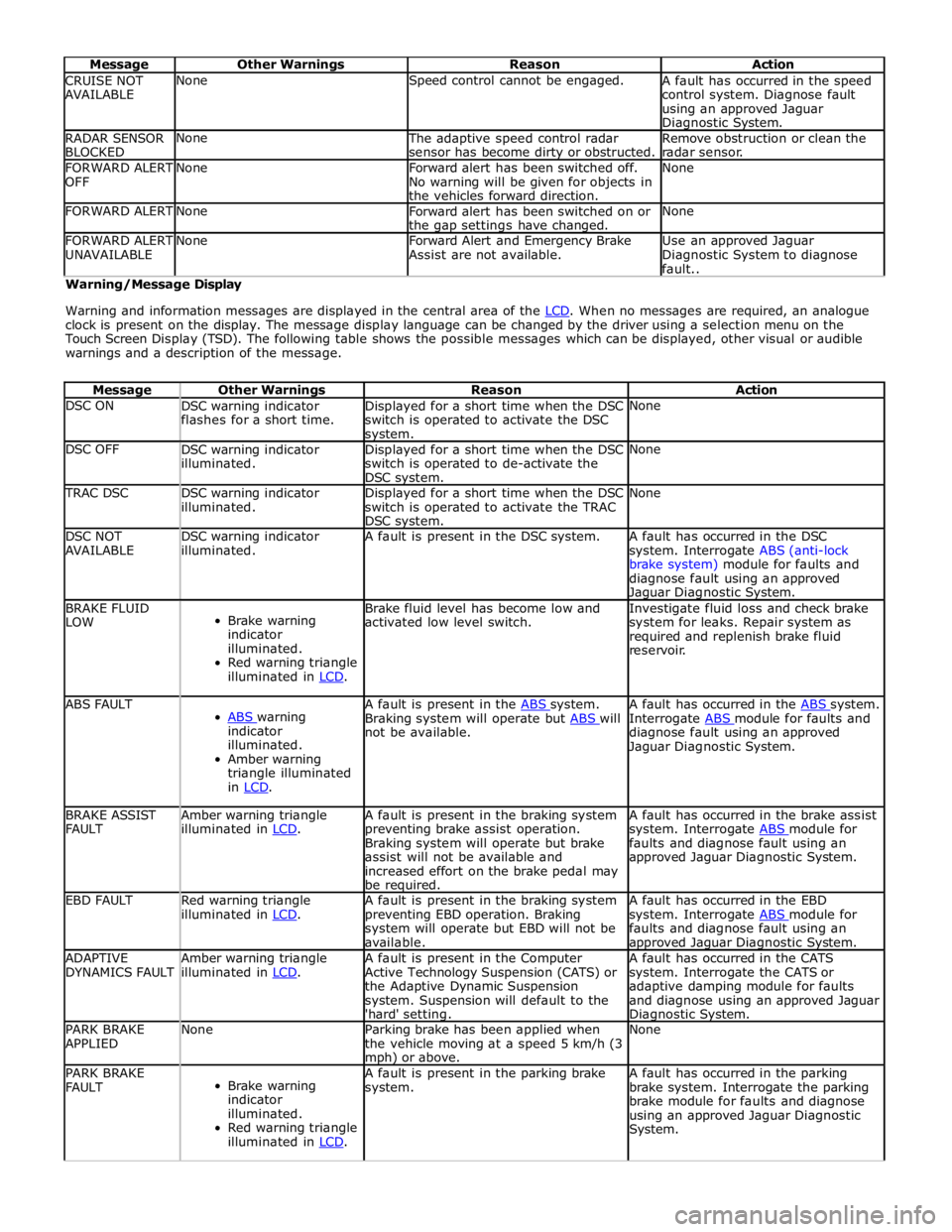
Message Other Warnings Reason Action CRUISE NOT
AVAILABLE None Speed control cannot be engaged.
A fault has occurred in the speed
control system. Diagnose fault
using an approved Jaguar Diagnostic System. RADAR SENSOR
BLOCKED None
The adaptive speed control radar
sensor has become dirty or obstructed. Remove obstruction or clean the
radar sensor. FORWARD ALERT
OFF None
Forward alert has been switched off.
No warning will be given for objects in
the vehicles forward direction. None FORWARD ALERT None
Forward alert has been switched on or
the gap settings have changed. None FORWARD ALERT
UNAVAILABLE None
Forward Alert and Emergency Brake
Assist are not available. Use an approved Jaguar
Diagnostic System to diagnose
fault.. Warning/Message Display
Warning and information messages are displayed in the central area of the LCD. When no messages are required, an analogue clock is present on the display. The message display language can be changed by the driver using a selection menu on the
Touch Screen Display (TSD). The following table shows the possible messages which can be displayed, other visual or audible
warnings and a description of the message.
Message Other Warnings Reason Action DSC ON
DSC warning indicator
flashes for a short time. Displayed for a short time when the DSC
switch is operated to activate the DSC system. None DSC OFF
DSC warning indicator
illuminated. Displayed for a short time when the DSC
switch is operated to de-activate the
DSC system. None TRAC DSC
DSC warning indicator
illuminated. Displayed for a short time when the DSC
switch is operated to activate the TRAC
DSC system. None DSC NOT
AVAILABLE DSC warning indicator
illuminated. A fault is present in the DSC system.
A fault has occurred in the DSC
system. Interrogate ABS (anti-lock
brake system) module for faults and
diagnose fault using an approved Jaguar Diagnostic System. BRAKE FLUID
LOW
Brake warning
indicator
illuminated.
Red warning triangle
illuminated in LCD. Brake fluid level has become low and
activated low level switch. Investigate fluid loss and check brake
system for leaks. Repair system as
required and replenish brake fluid
reservoir. ABS FAULT
ABS warning indicator
illuminated.
Amber warning
triangle illuminated
in LCD. A fault is present in the ABS system. Braking system will operate but ABS will not be available. A fault has occurred in the ABS system. Interrogate ABS module for faults and diagnose fault using an approved
Jaguar Diagnostic System. BRAKE ASSIST
FAULT Amber warning triangle
illuminated in LCD. A fault is present in the braking system
preventing brake assist operation.
Braking system will operate but brake
assist will not be available and
increased effort on the brake pedal may
be required. A fault has occurred in the brake assist
system. Interrogate ABS module for faults and diagnose fault using an
approved Jaguar Diagnostic System. EBD FAULT
Red warning triangle
illuminated in LCD. A fault is present in the braking system
preventing EBD operation. Braking
system will operate but EBD will not be
available. A fault has occurred in the EBD
system. Interrogate ABS module for faults and diagnose fault using an approved Jaguar Diagnostic System. ADAPTIVE
DYNAMICS FAULT Amber warning triangle
illuminated in LCD. A fault is present in the Computer
Active Technology Suspension (CATS) or
the Adaptive Dynamic Suspension
system. Suspension will default to the
'hard' setting. A fault has occurred in the CATS
system. Interrogate the CATS or
adaptive damping module for faults
and diagnose using an approved Jaguar Diagnostic System. PARK BRAKE
APPLIED None
Parking brake has been applied when
the vehicle moving at a speed 5 km/h (3 mph) or above. None PARK BRAKE
FAULT
Brake warning
indicator
illuminated.
Red warning triangle
illuminated in LCD. A fault is present in the parking brake
system. A fault has occurred in the parking
brake system. Interrogate the parking
brake module for faults and diagnose
using an approved Jaguar Diagnostic
System.
Page 1949 of 3039
systems.
A typical example of information transfer is vehicle speed information from the ABS (anti-lock brake system) module used to
control the automatic volume control function. The vehicle speed information from the ABS module is sent on the high speed
CAN network and collected by the instrument panel gateway. The signal is passed to the medium speed CAN network and onto the ICM gateway. The ICM calculates the volume adjustment required. The corrected audio volume level signal is sent on the
MOST network to the IAM or Power amplifier (dependant on vehicle equipment level) for output to the speaker system.
AUDIO SYSTEM USER CONTROLS
Touch-Screen
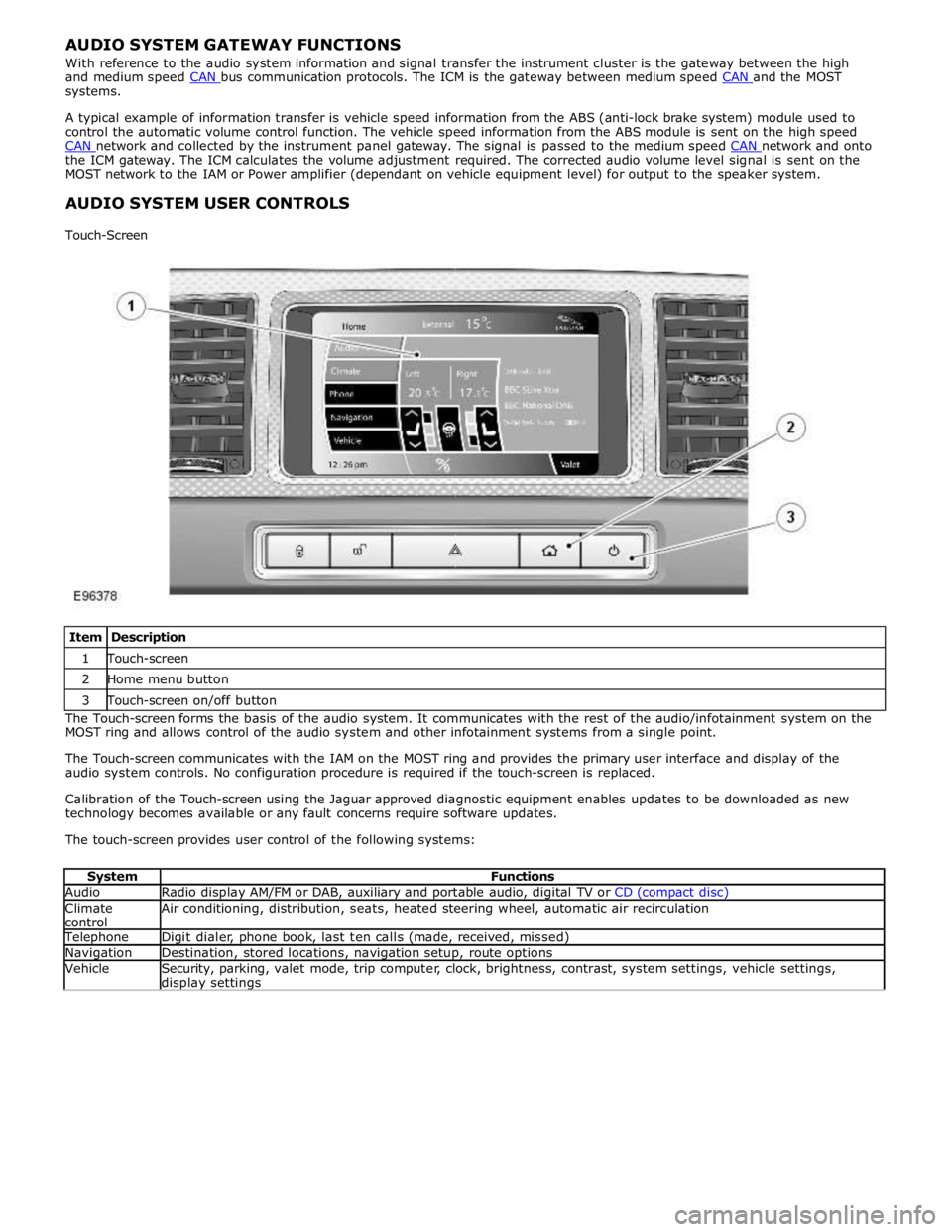
Item Description 1 Touch-screen 2 Home menu button 3 Touch-screen on/off button The Touch-screen forms the basis of the audio system. It communicates with the rest of the audio/infotainment system on the
MOST ring and allows control of the audio system and other infotainment systems from a single point.
The Touch-screen communicates with the IAM on the MOST ring and provides the primary user interface and display of the
audio system controls. No configuration procedure is required if the touch-screen is replaced.
Calibration of the Touch-screen using the Jaguar approved diagnostic equipment enables updates to be downloaded as new
technology becomes available or any fault concerns require software updates.
The touch-screen provides user control of the following systems:
System Functions Audio Radio display AM/FM or DAB, auxiliary and portable audio, digital TV or CD (compact disc) Climate
control Air conditioning, distribution, seats, heated steering wheel, automatic air recirculation Telephone Digit dialer, phone book, last ten calls (made, received, missed) Navigation Destination, stored locations, navigation setup, route options Vehicle
Security, parking, valet mode, trip computer, clock, brightness, contrast, system settings, vehicle settings, display settings
Page 1951 of 3039
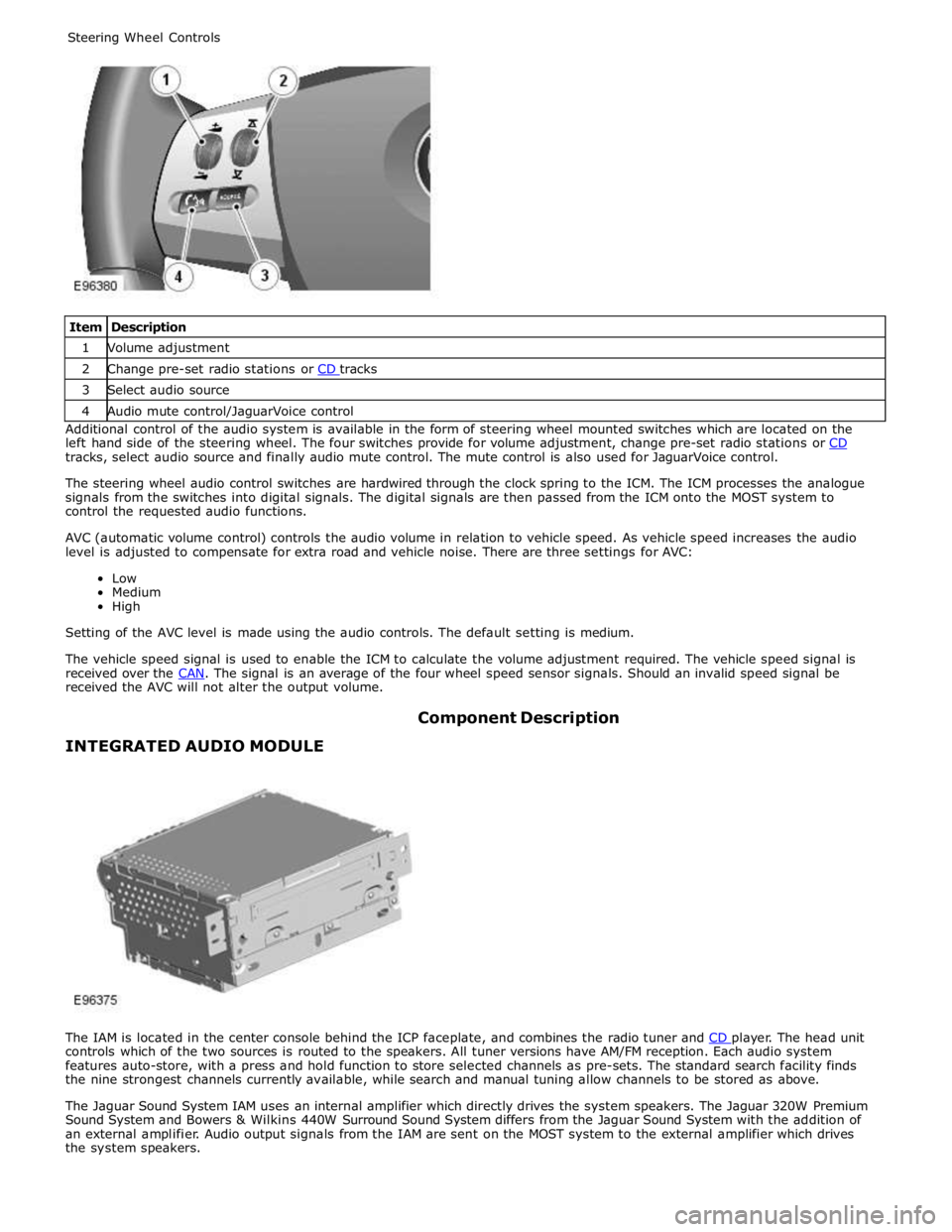
1 Volume adjustment 2 Change pre-set radio stations or CD tracks 3 Select audio source 4 Audio mute control/JaguarVoice control Additional control of the audio system is available in the form of steering wheel mounted switches which are located on the
left hand side of the steering wheel. The four switches provide for volume adjustment, change pre-set radio stations or CD tracks, select audio source and finally audio mute control. The mute control is also used for JaguarVoice control.
The steering wheel audio control switches are hardwired through the clock spring to the ICM. The ICM processes the analogue
signals from the switches into digital signals. The digital signals are then passed from the ICM onto the MOST system to
control the requested audio functions.
AVC (automatic volume control) controls the audio volume in relation to vehicle speed. As vehicle speed increases the audio
level is adjusted to compensate for extra road and vehicle noise. There are three settings for AVC:
Low
Medium
High
Setting of the AVC level is made using the audio controls. The default setting is medium.
The vehicle speed signal is used to enable the ICM to calculate the volume adjustment required. The vehicle speed signal is
received over the CAN. The signal is an average of the four wheel speed sensor signals. Should an invalid speed signal be received the AVC will not alter the output volume.
INTEGRATED AUDIO MODULE Component Description
The IAM is located in the center console behind the ICP faceplate, and combines the radio tuner and CD player. The head unit controls which of the two sources is routed to the speakers. All tuner versions have AM/FM reception. Each audio system
features auto-store, with a press and hold function to store selected channels as pre-sets. The standard search facility finds
the nine strongest channels currently available, while search and manual tuning allow channels to be stored as above.
The Jaguar Sound System IAM uses an internal amplifier which directly drives the system speakers. The Jaguar 320W Premium
Sound System and Bowers & Wilkins 440W Surround Sound System differs from the Jaguar Sound System with the addition of
an external amplifier. Audio output signals from the IAM are sent on the MOST system to the external amplifier which drives
the system speakers.
Page 1981 of 3039
Navigation Destination, stored locations, navigation setup, route options Vehicle
Security, parking, valet mode, trip computer, clock, brightness, contrast, system settings, vehicle settings, display settings The screen is a touch sensitive 7 inch LCD (liquid crystal display) VGA screen containing 800 x 480 pixels in a 15:9 format. The
screen processes its own video for system operation but receives the navigation graphics from the navigation computer.
Steering Wheel Controls
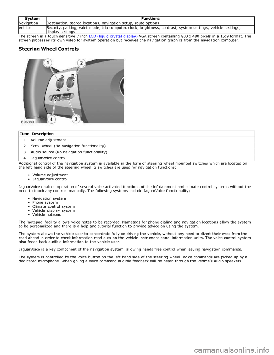
Item Description 1 Volume adjustment 2 Scroll wheel (No navigation functionality) 3 Audio source (No navigation functionality) 4 JaguarVoice control Additional control of the navigation system is available in the form of steering wheel mounted switches which are located on
the left hand side of the steering wheel. 2 switches are used for navigation functions;
Volume adjustment
JaguarVoice control
JaguarVoice enables operation of several voice activated functions of the infotainment and climate control systems without the
need to touch any controls manually. The following systems include JaguarVoice functionality;
Navigation system
Phone system
Climate control system
Vehicle display system
Vehicle notepad
The 'notepad' facility allows voice notes to be recorded. Nametags for phone dialing and navigation locations allow the system
to be personalized and there is a help and tutorial function to provide advice on using the system.
The system allows the vehicle user to concentrate fully on driving the vehicle, without any need to divert their eyes from the
road ahead in order to check information read outs on the vehicle instrument panel information units. The voice control system
also feeds back audible information to the vehicle user.
JaguarVoice is a key component of the navigation system, allowing hands free control when issuing navigation commands.
The system is controlled by the voice button on the left hand side of the steering wheel. Voice commands are picked up by a
dedicated microphone. When giving a voice command audible feedback will be heard through the vehicle’s audio speakers.
Page 2030 of 3039
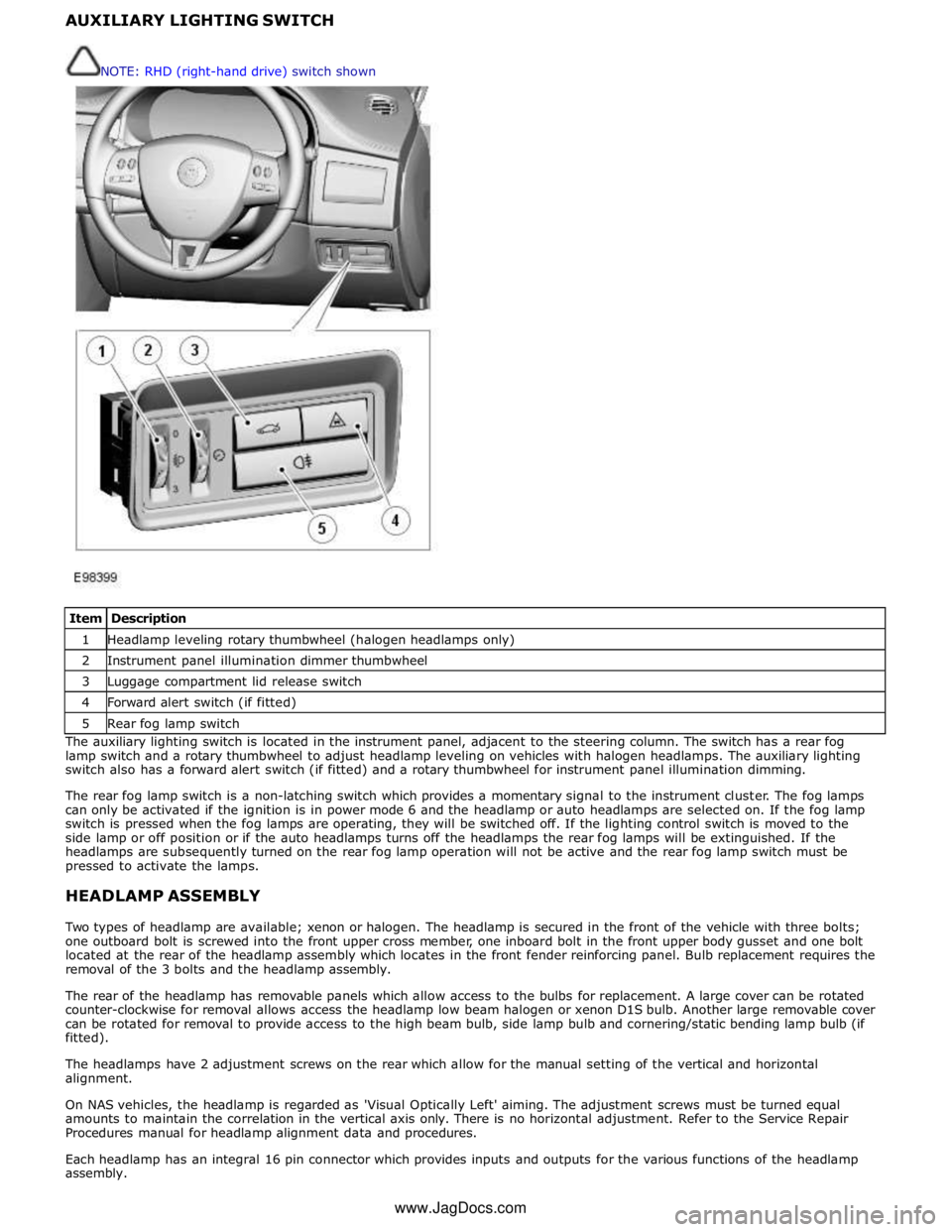
1 Headlamp leveling rotary thumbwheel (halogen headlamps only) 2 Instrument panel illumination dimmer thumbwheel 3 Luggage compartment lid release switch 4 Forward alert switch (if fitted) 5 Rear fog lamp switch The auxiliary lighting switch is located in the instrument panel, adjacent to the steering column. The switch has a rear fog
lamp switch and a rotary thumbwheel to adjust headlamp leveling on vehicles with halogen headlamps. The auxiliary lighting
switch also has a forward alert switch (if fitted) and a rotary thumbwheel for instrument panel illumination dimming.
The rear fog lamp switch is a non-latching switch which provides a momentary signal to the instrument cluster. The fog lamps
can only be activated if the ignition is in power mode 6 and the headlamp or auto headlamps are selected on. If the fog lamp
switch is pressed when the fog lamps are operating, they will be switched off. If the lighting control switch is moved to the
side lamp or off position or if the auto headlamps turns off the headlamps the rear fog lamps will be extinguished. If the
headlamps are subsequently turned on the rear fog lamp operation will not be active and the rear fog lamp switch must be
pressed to activate the lamps.
HEADLAMP ASSEMBLY
Two types of headlamp are available; xenon or halogen. The headlamp is secured in the front of the vehicle with three bolts;
one outboard bolt is screwed into the front upper cross member, one inboard bolt in the front upper body gusset and one bolt
located at the rear of the headlamp assembly which locates in the front fender reinforcing panel. Bulb replacement requires the
removal of the 3 bolts and the headlamp assembly.
The rear of the headlamp has removable panels which allow access to the bulbs for replacement. A large cover can be rotated
counter-clockwise for removal allows access the headlamp low beam halogen or xenon D1S bulb. Another large removable cover
can be rotated for removal to provide access to the high beam bulb, side lamp bulb and cornering/static bending lamp bulb (if
fitted).
The headlamps have 2 adjustment screws on the rear which allow for the manual setting of the vertical and horizontal
alignment.
On NAS vehicles, the headlamp is regarded as 'Visual Optically Left' aiming. The adjustment screws must be turned equal
amounts to maintain the correlation in the vertical axis only. There is no horizontal adjustment. Refer to the Service Repair
Procedures manual for headlamp alignment data and procedures.
Each headlamp has an integral 16 pin connector which provides inputs and outputs for the various functions of the headlamp
assembly. NOTE: RHD (right-hand drive) switch shown
www.JagDocs.com