stop start JAGUAR XFR 2010 1.G Workshop Manual
[x] Cancel search | Manufacturer: JAGUAR, Model Year: 2010, Model line: XFR, Model: JAGUAR XFR 2010 1.GPages: 3039, PDF Size: 58.49 MB
Page 103 of 3039
General Information - Road/Roller Testing
Description and Operation Published: 11-May-2011
Road or roller testing may be carried out for various reasons and a procedure detailing pre-test checks, through engine starting
and stopping, pre-driving checks, on-test checks to final checks on completion of the test is given in this section.
Unless complete vehicle performance is being checked, the full road test procedure need not be carried out. Instead, those
items particularly relevant to the system/s being checked can be extracted.
Pre - Test Checks
WARNING: If the brake system hydraulic fluid level is low, pedal travel is excessive or a hydraulic leak is found, do not
attempt to road test the vehicle until the reason for the low fluid level, excessive pedal travel or hydraulic leak is found and
rectified.
It is suggested that pre-test checks, and functional tests of those systems/circuits which affect the safe and legal operations
of the vehicle, such as brakes, lights and steering, should always be carried out before the road or roller test.
Engine oil level
Engine coolant level
Tires, for correct pressure, compatible types and tread patterns, and wear within limits
There is sufficient fuel in the tank to complete the test
All around the engine, transmission and under the vehicle for oil, coolant, hydraulic and fuel leaks. Make a note of any
apparent leaks and wipe off the surrounding areas to make it easier to identify the extent of the leak on completion of
the test
Starting the Engine
CAUTION: On initial drive away from cold and within the first 1.5 km (1 mile), do not depress accelerator pedal beyond
half travel until the vehicle has attained a minimum speed of 25 km/h (15 miles/h). Never operate at high engine speed or
with the accelerator pedal at full travel whilst the engine is cold.
With the ignition switched off, check:
The parking brake is applied
The transmission selector lever is in Park
All instrument gauges (except fuel gauge) read zero
With the ignition switched on, check:
Ignition controlled warning lamps come on
Engine coolant temperature gauge registers a reading compatible with the engine coolant temperature
Fuel gauge registers a reading appropriate to the fuel level in the tank
The operation of the parking brake and brake fluid level warning lamps
On Road or Roller Test Check:
CAUTION: If road testing, check the brake operation while still travelling at low speed before continuing with the test. If
the brakes pull to one side, or appear to be otherwise faulty, do not continue with the road test until the fault has been found
and rectified.
Initial gear engagement is smooth
Parking brake control operates smoothly and the parking brake releases quickly and completely
Transmission takes up the drive smoothly, without judder
The engine power output is satisfactory, full power is achieved, acceleration is smooth and pedal operation not stiff or
heavy, and engine speed returns to idle correctly
There is no excessive or abnormally colored smoke from the engine under normal driving, heavy load or overrun
conditions
Steering operation, including power steering, is smooth, accurate, not excessively heavy or with excessive free play or
vibration. Does not pull to one side and self centres smoothly after cornering
Speedometer, oil pressure warning lamp, coolant temperature gauge and tachometer register the correct readings or
operate correctly
Switches and controls operate smoothly and positively, warning lamps operate correctly and the direction indicator
control self cancels when the steering is returned to the straight ahead position
Heating and ventilation systems work correctly and effectively
Brake operation and efficiency
Brake Testing
WARNING: When brake testing, avoid breathing the smoke or fumes from hot brakes, this may contain asbestos dust
which is hazardous to health, see Health and Safety Precautions.
Page 135 of 3039

DTC Description Possible Causes Action error following
re-programming
Noise/EMC related error network for interference/EMC related issues B1009-63 Ignition Authorisation
- Circuit/component
protection time-out
CJB fault
Low speed CAN fault
Instrument cluster fault
Low battery voltage <9V
Check Power and Ground supplies to CJB and
instrument cluster. Check CAN communications
between CJB and instrument cluster. Check
battery is in fully charged and serviceable
condition, refer to the battery care manual B1009-64 Ignition Authorisation
- Signal plausibility
failure
CJB fault
Low speed CAN fault
Instrument cluster fault
Check power and ground supplies to CJB and
instrument cluster. Check CAN communications
between CJB and instrument cluster B102B-67
Passive Key - Signal
incorrect after event
CJB fault
Low speed CAN fault
Remote Keyless Entry (RKE)
module fault
Write target SID
synchronisation error
following re-programming
Check power and ground supplies to CJB and RKE
module. Check CAN communications between CJB
and RKE module. Re-synchronise ID by
re-configuring the RKE module as a new module B102B-87
Passive Key - Missing
message
CJB fault
Low speed CAN fault
RKE module fault
Key fob battery low/battery
contact issue
Interference from other RF
signal
EMC/noise
Receiver fault
Receiver not programmed
correctly
Serial communications fault
(between receiver and RKE
module)
Key fault
Passive antenna fault
Confirm placement of key
within vehicle
Check power and ground supplies to CJB, RKE
module and receiver. Check CAN communications
between CJB and instrument cluster. Check key
fob battery. Confirm vehicle surroundings, move
vehicle. Check CAN network for interference/EMC
related issues. Disconnect battery, then
re-connect - confirm operation by re-programming
keys. Check serial circuit between receiver and
RKE module. Confirm spare key works. Refer to
the electrical circuit diagrams and test circuits to
all 3 antennas. Check whereabouts of key B1084-13
Boot/Trunk Motor
Close Switch - Circuit
open
Trunk latch open signal
circuit - open circuit
Refer to the electrical circuit diagrams and check
trunk latch open signal circuit for open circuit B1087-83
LIN Bus "A" - Value of
signal protection
calculation incorrect
Checksum of the received
LIN frame from battery
backed sounder, roof header
console, and/or rain/light
sensor is incorrect
Check operation of rain/light sensor by covering
sensor or applying water to screen, install a new
sensor as required B1087-88 LIN Bus "A" - Bus off
Bus off. Battery backed
sounder, roof header
console, and/or rain/light
sensor LIN circuit - short to
ground, power
Carry out any pinpoint tests associated with this
DTC using the manufacturer approved diagnostic
system. Refer to the electrical circuit diagrams
and check battery backed sounder, roof header
console, and rain/light sensor LIN circuit for short
to ground, power B108A-11
Start Button - Circuit
short to ground
Start/Stop switch analogue
input circuits 1 or 2 - short
to ground
Refer to the electrical circuit diagrams and check
Start/Stop switch analogue input circuits 1 and 2
for short to ground B108A-12
Start Button - Circuit
short to battery
Start/Stop switch analogue
input circuits 1 or 2 - short
to power
Refer to the electrical circuit diagrams and check
Start/Stop switch analogue input circuits 1 and 2
for short to power B1095-12
Wiper On/Off Relay -
Circuit short to battery
Wiper On/Off relay control
circuit - short to power
Carry out any pinpoint tests associated with this
DTC using the manufacturer approved diagnostic
system. Refer to the electrical circuit diagrams
and check wiper On/Off relay control circuit for www.JagDocs.com
Page 220 of 3039

DTC Description Possible Causes Action B100A-51 Fuel Pump Authorisation
- Not programmed
RJB fault
Low speed CAN fault
Instrument cluster fault
Check power and ground supplies to RJB. Check CAN
communications between RJB and instrument
cluster. Check power and ground supplies to
instrument cluster B100A-62 Fuel Pump Authorisation
- Signal compare failure
Low speed CAN fault
RJB fault
Instrument cluster fault
Incorrect module
installed
(RJB/Instrument cluster)
Write target SID
synchronisation error
following
re-programming
Noise/EMC related error
Check CAN communications between RJB and
instrument cluster. Check power and ground supplies
to RJB and instrument cluster. Confirm correct
module installed. Re-synchronise ID by
re-configuring the RJB as a new module. Check CAN
network for interference/EMC related issues B100A-63 Fuel Pump Authorisation
- Circuit/component
protection time-out
RJB fault
Low speed CAN fault
Instrument cluster fault
Low battery voltage <9V
Check power and ground supplies to RJB and
instrument cluster. Check CAN communications
between RJB and instrument cluster. Check battery
is in fully charged and serviceable condition, refer to
the battery care manual B1026-12
Steering Column Lock -
Circuit short to battery
Steering column lock
ground circuit - short to
power
Refer to the electrical circuit diagrams and check
steering column lock ground circuit for short to
power B1087-83
LIN Bus "A" - Value of
signal protection
calculation incorrect
The checksum of the
received LIN frame is
incorrect
Check the battery monitoring system and rear
parking aid system for DTCs and refer to relevant
DTC Index B1087-86
LIN Bus "A" - Signal
invalid
The header of the LIN
message received is
incorrect
Carry out any pinpoint test associated with this DTC
using the manufacturer approved diagnostic system.
Check the battery monitoring system and rear
parking aid system for DTCs and refer to relevant
DTC Index B1087-88 LIN Bus "A" - Bus off
Battery monitoring
system LIN circuit -
short to ground, power
Carry out any pinpoint test associated with this DTC
using the manufacturer approved diagnostic system.
Refer to the electrical circuit diagrams and check
battery monitoring system LIN circuit for short to
ground, power B108A-23
Start Button - Signal
stuck low
Start/Stop switch digital
input signal circuit -
stuck low
Carry out any pinpoint test associated with this DTC
using the manufacturer approved diagnostic system.
Refer to the electrical circuit diagrams and check
Start/Stop switch digital input signal circuit for short
to ground B10A1-11 Trailer Tow Detection -
Circuit short to ground
Trailer tow detection
digital input circuit -
short to ground
Carry out any pinpoint test associated with this DTC
using the manufacturer approved diagnostic system.
Refer to the electrical circuit diagrams and check
trailer tow detection digital input circuit for short to
ground B10AF-12
Blower Fan Relay -
Circuit short to battery
High Side output not
driven - Diagnosis
feedback indicates
output is short to power
Refer to the electrical circuit diagrams and check
blower motor supply circuit for short to power B10AF-14
Blower Fan Relay -
Circuit short to ground
or open
High Side output not
driven - Diagnosis
feedback indicates
output is short to
ground, open circuit
Refer to the electrical circuit diagrams and check
blower motor supply circuit for short to ground, open
circuit
Page 300 of 3039
Noise Conditions
Gear noise is typically a howling or whining due to gear damage or incorrect bearing preload. It can occur at various
speeds and driving conditions, or it can be continuous
Chuckle is a particular rattling noise that sounds like a stick against the spokes of a spinning bicycle wheel. It occurs
while decelerating from approximately 64 km/h (40 miles/h) and can usually be heard all the way to a stop. The
frequency varies with vehicle speed
Knock is very similar to chuckle, though it may be louder and occurs on acceleration or deceleration. The tear down will
disclose what has to be corrected
Check and rule out tires, exhaust and trim items before disassembling the transmission to diagnose and correct gear noise.
The noises described under Road Test usually have specific causes that can be diagnosed by observation as the unit is
disassembled. The initial clues are the type of noise heard on the road test and the driving conditions.
Vibration Conditions
wear. NOTE: New Constant Velocity (CV) joints should not be installed unless disassembly and inspection revealed unusual
Clicking, popping or grinding noises may be caused by the following:
Cut or damaged CV joint boots resulting in inadequate or contaminated lubricant in the outboard or inboard CV joint
bearing housings
Loose CV joint boot clamps
Another component contacting the rear drive half shaft
Worn, damaged or incorrectly installed wheel bearing, suspension or brake component
Vibration at highway speeds may be caused by the following:
Out-of-balance front or rear wheels
Out-of-round tires
Driveline imbalance
Driveline run-out (alignment)
NOTE: Rear drive half shafts are not balanced and are not likely to contribute to rotational vibration disturbance.
Shudder or vibration during acceleration (including from rest) may be caused by the following:
Driveline alignment
Excessively worn or damaged outboard or inboard CV joint bearing housing
Excessively high CV joint operating angles caused by incorrect ride height. Check ride height, verify correct spring rate
and check items under Inoperative Conditions
Excessively worn driveshaft components
Leakage Conditions
1. Inspect the CV joint boots for evidence of cracks, tears or splits.
2. Inspect the underbody for any indication of grease splatter in the vicinity of the rear drive half shaft, outboard and
inboard CV joint boot locations, which is an indication of CV joint boot or CV joint boot clamp damage.
3. Inspect the inboard CV joint bearing housing seal for leakage.
Inoperative Conditions
If a CV joint or rear drive half shaft pull-out occurs, check the following:
suspension components for correct location, damage or wear
bushings for wear
subframe for damage
bent or worn components
- Stabilizer bar link
- Left-hand rear suspension lower arm and bushing
- Right-hand rear suspension lower arm and bushing
- Rear wheel hub and rear drive half shaft
Road Test
A gear-driven unit will produce a certain amount of noise. Some noise is acceptable and may be audible at certain speeds or
under various driving conditions as on a newly paved blacktop road. The slight noise is in no way detrimental and must be
considered normal.
The road test and customer interview (if available) provide information needed to identify the condition and give direction to
the correct starting point for diagnosis.
1. Make notes throughout the diagnosis routine. Make sure to write down even the smallest piece of information, because
Page 443 of 3039

7 Initiators 8 TPMS module 9 Instrument cluster
Tire Pressure Monitoring System (TPMS) System Operation
The controlling software for the Tire Pressure Monitoring System (TPMS) is located within a Tire Pressure Monitoring System
Module. The software detects the following:
When the tire pressure is below the recommended low pressure value - under inflated tire.
The location of the tire on the vehicle that is below the recommended pressure.
Malfunction warning.
The TPMS system comprises:
Tire pressure monitoring system module located below the right-hand front seat.
Tire pressure receiver located near the gear shifter within the floor console.
Two front initiators positioned forward of the wheels and behind the fender splash shields.
Two rear initiators positioned rearward of the wheels and assembled on dedicated brackets located behind the fender
splash shields.
Four sensors, each sensor is integral with a tire valve and located within the tire; the space saver spare wheel is not
fitted with a sensor.
The four initiators are hard wired to the TPMS module. The initiators transmit 125 KHz Low Frequency (LF) signals to the tire
pressure sensors which respond by modifying the mode status within the Radio Frequency (RF) transmission. The 315 or 433
MHz RF signals are detected by the tire pressure receiver which is connected directly to the TPMS module. The received RF
signals from the tire pressure sensors are passed to the TPMS module and contain identification, pressure, temperature and
acceleration information for each wheel and tire.
The TPMS module communicates with the instrument cluster via the medium speed CAN bus to provide the driver with
appropriate warnings. The TPMS module also indicates status or failure of the TPMS or components.
Tire Location and Identification
The TPMS can identify the position of the wheels on the vehicle and assign a received tire pressure sensor identification to a
specific position on the vehicle, for example front left, front right, rear left and rear right. This feature is required because of
the different pressure targets and threshold that could exist between the front and rear tires.
The wheel location is performed automatically by the TPMS module using an 'auto-location' function. This function is fully
automatic and requires no input from the driver. The TPMS module automatically re-learns the position of the wheels on the
vehicle if the tire pressure sensors are replaced or the wheel positions on the vehicle are changed.
The TPMS software can automatically detect, under all operating conditions, the following:
one or more new tire pressure sensors have been fitted
one or more tire pressure sensors have stopped transmitting
TPMS module can reject identifications from tire pressure sensors which do not belong to the vehicle
two 'running' wheels on the vehicle have changed positions.
If a new tire pressure sensor is fitted on any 'running' wheel, the module can learn the new sensor identification automatically
through the tire learn and location process.
The tire-learn and location process is ready to commence when the vehicle has been stationary or traveling at less than 12
mph (20 km/h) for 15 minutes. This is known as 'parking mode'. The learn/locate process requires the vehicle to be driven at
speeds of more than 12 mph (20 km/h) for 15 minutes. If the vehicle speed reduces to below 12 mph (20 km/h), the learn
process timer is suspended until the vehicle speed increases to more than 12 mph (20 km/h), after which time the timer is
resumed. If the vehicle speed remains below 12 mph (20 km/h) for more than 15 minutes, the timer is set to zero and process
starts again.
Low Pressure Monitoring
The tire low pressure sensor transmits by RF (315 MHz or 433 MHz depending on market) signal. These signals contain data
which corresponds to tire low pressure sensor identification, tire pressure, tire temperature, acceleration and tire low pressure
sensor mode.
Each time the vehicle is driven, the tire pressure monitoring system module activates each LF antenna in turn. The
corresponding tire low pressure sensor detects the LF signal and responds by modifying the mode status within the RF
transmission.
The system enters 'parking mode' after the vehicle speed has been less than 20 km/h (12.5 miles/h) for 12 minutes. In parking
mode the tire low pressure sensors transmit a coded signal to the tire pressure monitoring system module once every 13
hours. If the tire pressure decreases by more than 0.06 bar (1 lbf/in²) the tire low pressure sensor will transmit more often as
pressure is lost.
As each wheel responds to the LF signal from the tire pressure monitoring system module, it is assigned a position on the
vehicle and is monitored for the remainder of that drive cycle in that position.
Page 590 of 3039
Does the brake pedal return to its original position? Yes
No action required, vehicle is OK.
No
GO to K2. K2: CHECK FOR BRAKE PEDAL BINDING 1 Disconnect the brake booster from the brake pedal. Check the brake pedal to ensure free operation. Is the brake pedal operating freely? Yes
Install a new brake booster as required. REFER to:
Brake Booster (206-07 Power Brake Actuation, Removal and Installation), Brake Booster - RHD (206-07, Removal and Installation).
Re-test the system for normal operation.
No
Repair or install new brake pedal. Re-test the system for normal operation. Component Tests
Brake Booster
1. Check all hoses and connections. All unused vacuum connectors should be capped. Hoses and their connections should
be correctly secured and in good condition with no holes and no collapsed areas. Inspect the valve on the brake booster
for damage.
2. Check the hydraulic brake system for leaks or low fluid.
3. With the automatic transmission in PARK, stop the engine and apply the parking brake. Pump the brake pedal several
times to exhaust all vacuum in the system. With the engine switched off and all vacuum in the system exhausted,
apply the brake pedal and hold it down. Start the engine. If the vacuum system is operating, the brake pedal will tend
to move downward under constant foot pressure. If no motion is felt, the vacuum booster system is not functioning.
4. Remove the vacuum hose from the brake booster. Manifold vacuum should be available at the brake booster end of the
hose with the engine at idle speed and the automatic transmission in PARK. Make sure that all unused vacuum outlets
are correctly capped, hose connectors are correctly secured and vacuum hoses are in good condition. When it is
established that manifold vacuum is available to the brake booster, connect the vacuum hose to the brake booster and
repeat Step 3. If no downward movement of the brake pedal is felt, install a new brake booster.
5. Operate the engine for a minimum of 10 seconds at a fast idle. Stop the engine and allow the vehicle to stand for 10
minutes. Then, apply the brake pedal with approximately 89 N (20lb) of force. The pedal feel (brake application) should
be the same as that noted with the engine running. If the brake pedal feels hard (no power assist), install a new valve
and then repeat the test. If the brake pedal still feels hard, install a new brake booster. If the brake pedal movement
feels spongy, bleed the brake system.
REFER to: Brake System Bleeding (206-00 Brake System - General Information, General Procedures). Brake Master Cylinder
Usually, the first and strongest indicator of anything wrong in the brake system is a feeling through the brake pedal. In
diagnosing the condition of the brake master cylinder, check pedal feel as evidence of a brake concern. Check for brake warning
lamp illumination and the brake fluid level in the brake master cylinder reservoir.
Normal Conditions
The following conditions are considered normal and are not indications that the brake master cylinder is in need of repair.
Modern brake systems are designed to produce a pedal effort that is not as hard as in the past. Complaints of light
pedal efforts should be compared to the pedal efforts of another vehicle of the same model and year.
The fluid level will fall with brake pad wear.
Abnormal Conditions
Changes in the brake pedal feel or brake pedal travel are indicators that something could be wrong in the brake system. The
diagnostic procedure and techniques use brake pedal feel, warning indicator illumination and low brake fluid level as indicators
to diagnosing brake system concerns. The following conditions are considered abnormal and indicate that the brake master
cylinder is in need of repair:
NOTE: Prior to carrying out any diagnosis, make sure the brake system warning indicator is functional.
Brake pedal goes down fast. This could be caused by an external or internal leak.
Brake pedal goes down slowly. This could be caused by an internal or external leak.
Brake pedal is low or feels spongy. This condition may be caused by no fluid in the brake master cylinder, reservoir cap
vent holes clogged or air in the hydraulic system.
Brake pedal effort is excessive. This may be caused by a bind or obstruction in the pedal/linkage, a faulty non-return
valve, booster or insufficient booster vacuum.
Rear brakes lock up during light pedal force. This may be caused by damaged brake pads, a partially applied parking
brake, a damaged ABS sensor or bearing failure.
Brake pedal effort erratic. This condition could be caused by the brake booster or incorrectly installed brake pads.
Brake warning indicator is on. This may be caused by low fluid level or float assembly damaged. www.JagDocs.com
Page 727 of 3039
between moving components such as the steering wheel to steering column shroud.
Grunt (Squawk/Whoop)
Grunt is a 'honking' sound elicited when coming off one of the steering stops. Grunt is generally excited during parking
manoeuvres with a low to medium speed steering input.
Hiss (Swish)
Hiss or Valve Hiss is a high-frequency sound coming from the steering gear when the system is loaded. It is a rushing or
'swish' noise that doesn't change frequency with RPM. Hiss is the general noise generated by the flow of hydraulic fluid through
restrictions in the steering system. Restrictions include the rotary steering valve, power steering tubes, connectors, tuning
orifices, etc. Hiss can be air-borne and structure-borne, but the structure-borne path through the steering intermediate shaft is
usually dominant.
Moan (Groan)
Moan is the general structure-borne noise of the steering system. Moan is primarily transmitted to the driver via the body
structure through the pump mount, engine mounts, power steering lines and power steering brackets. On some vehicles, moan
is a loud humming noise, often present when the wheel is turned and the system is loaded. It may change frequency with
engine RPM and if the system is loaded or unloaded.
Steering Gear Knock (Steering Gear Slap)
CAUTION: DO NOT attempt to adjust the steering gear yoke. Failure to follow this instruction will invalidate the steering
gear warranty.
Steering gear knock is a rattle sound and steering wheel vibration caused by separation of the steering gear and pinion while
driving over bumps. It is a structure-borne noise transmitted through the intermediate shaft and column. Steering gear knock
can also be heard as a 'thump' or impact noise that occurs with the vehicle stationary when the steering wheel is released
from a loaded position and allowed to return to rest. Noise occurs with the engine on or off.
Rattles
Rattles are noises caused by knocking or hitting of components in the steering system. Steering rattles can occur in the engine
compartment, the suspension, or the passenger compartment. Rattles can be caused by loose components, movable and
flexible components, and improper clearances.
Squeaks/Scrapes
Squeaks/Scrapes are noises due to friction or component rubbing anywhere in the steering system. Squeaks/Scrapes have
appeared in steering linkages and joints, in column components and in column and steering wheel trim.
Weep
Weep is an air-borne noise, occasionally generated when turning the steering across lock at a constant rate. When present on
a vehicle the noise, once initiated can often be maintained across a large proportion of the available steering movement.
Whistle
Whistle is similar to hiss but is louder and of a higher frequency. It is also more of a pure tone noise than hiss. Whistle is
air-borne and is generated by a high flow rate of hydraulic fluid through a small restriction.
Zip
Zip noise is the air-borne noise generated by power steering pump cavitation when power steering fluid does not flow freely
through the suction hose from the reservoir to the pump. Zip primarily occurs during cold weather at start-up.
Steering System Vibrations and Harshness
Buzz
Buzz is a tactile rotary vibration felt in the steering wheel when steering inputs are slow. Buzz can also be called a grinding
feel and it is closely related to grunt and is caused by high system gain with low damping. Buzz is generally excited during
parking manoeuvres with low to medium speed steering input.
Buzz (Electrical)
A different steering buzz can be caused by pulse width modulated (PWM) electric actuators used in variable assist steering
systems. This buzz is felt by turning the ignition key to run without starting the engine and holding onto the steering wheel.
In extreme cases, the buzz can be felt with the engine running also.
Column/Steering Wheel Shake
Column shake is a low frequency vertical vibration excited by primary engine vibrations.
Nibble (Shimmy)
Page 729 of 3039
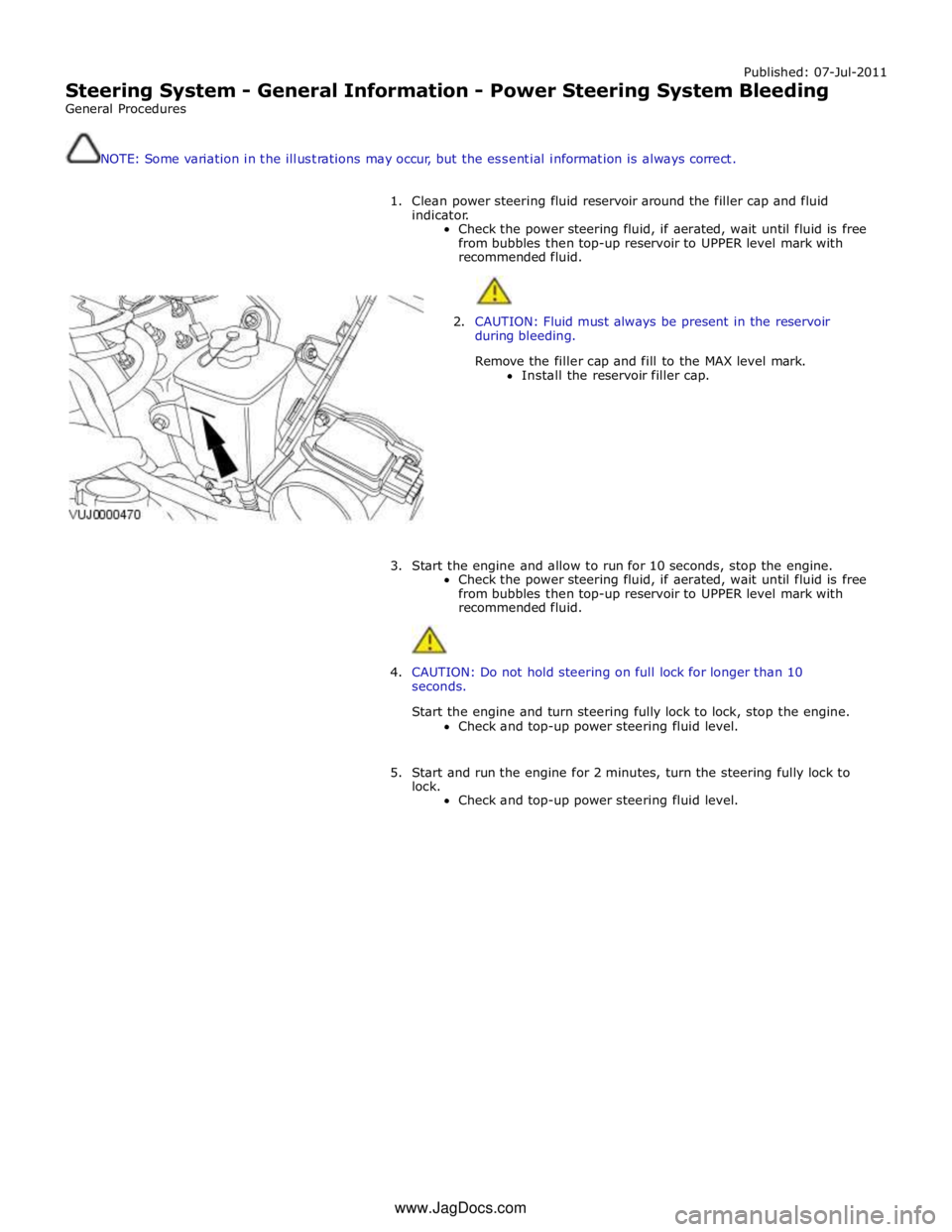
Published: 07-Jul-2011
Steering System - General Information - Power Steering System Bleeding
General Procedures
NOTE: Some variation in the illustrations may occur, but the essential information is always correct.
1. Clean power steering fluid reservoir around the filler cap and fluid
indicator.
Check the power steering fluid, if aerated, wait until fluid is free
from bubbles then top-up reservoir to UPPER level mark with
recommended fluid.
2. CAUTION: Fluid must always be present in the reservoir
during bleeding.
Remove the filler cap and fill to the MAX level mark.
Install the reservoir filler cap.
3. Start the engine and allow to run for 10 seconds, stop the engine.
Check the power steering fluid, if aerated, wait until fluid is free
from bubbles then top-up reservoir to UPPER level mark with
recommended fluid.
4. CAUTION: Do not hold steering on full lock for longer than 10
seconds.
Start the engine and turn steering fully lock to lock, stop the engine.
Check and top-up power steering fluid level.
5. Start and run the engine for 2 minutes, turn the steering fully lock to
lock.
Check and top-up power steering fluid level. www.JagDocs.com
Page 813 of 3039
Component Tests
Engine Oil Leaks
NOTE: Before installing new gaskets or oil seals, make sure that the fault is clearly established.
If the oil leak cannot be identified clearly by a visual inspection, carry out an Ultraviolet test:
Fluorescent Oil Additive Method
1. Clean the engine with a suitable cleaning fluid (brake cleaner).
2. Drain the engine oil and refill with recommended oil, premixed with Diesel Engine Oil Dye or equivalent. Use a minimum
14.8 ml (0.5 ounce) to a maximum 29.6 ml (1 ounce) of fluorescent additive to all engines. If oil is not premixed,
fluorescent additive must first be added to the crankcase.
3. Run engine for 15 minutes. Stop the engine and inspect all seal and gasket areas for leaks using a 12 Volt Master UV
Diagnostic Inspection Kit or equivalent. A clear bright yellow or orange area will identify leak. For extremely small
leaks, several hours may be required for the leak to appear.
4. As necessary, pressurize the main oil gallery system to locate leaks due to incorrectly sealed, loose or cocked plugs. If
the flywheel bolts leak oil, look for sealer on the threads.
5. Repair all leaks as necessary.
Compression Test General Remarks
NOTES:
Removing fuses and disconnecting electrical components may cause the Engine Control Module (ECM) to log Diagnostic
Trouble Codes (DTCs). After the measurements have been carried out, DTCs should be cleared from memory by connecting to
the Manufacturer Approved Diagnostic System.
Only check the compression pressure with the valves set to the prescribed clearance (if this can be adjusted).
The compression pressure should be checked with the engine at normal operating temperature.
Check the Compression Pressure
WARNING: Move gear selector lever to 'P' position. Failure to follow this instruction may result in personal injury.
1. Remove the fuel pump relay.
2. Start the engine - the engine will start, run for a few seconds then stall.
3. Remove the spark plugs.
4. Install the compression tester.
5. Install an auxiliary starter switch in the starting circuit. With the ignition switch OFF, using the auxiliary starter switch,
crank the engine a minimum of five compression strokes and record the highest reading. Note the approximate number
of compression strokes required to obtain the highest reading.
6. Repeat the test on each cylinder, cranking the engine approximately the same number of compression strokes.
7. Install the removed components in reverse order, observing the specified tightening torques.
8. Clear all DTCs from the ECM.
Interpretation of the Results
NOTE: Due to the possibility of loose carbon that has become trapped between the valve face and seat effecting the
pressure readings, when carrying out a compression test and cylinders are found to have low pressures, install the spark plugs,
road test the vehicle and re-test the suspect cylinders. If the correct pressures are restored, no further action is required.
The indicated compression pressures are considered within specification if the lowest reading cylinder is within 75% of the
highest reading.
If the cylinder pressures are found to be low, carry out a leakdown test to determine the location of the fault (if any leakback
can be heard through the engine breather system suspect the piston rings, if any leakback can be heard through the inlet
system suspect the inlet valve or seat, if any leakback can be heard through the exhaust manifold suspect the exhaust valve
or seat. If the measurements for two cylinders next to each other are both too low then it is very likely that the cylinder head
gasket between them is burnt through. This can also be recognized by traces of engine oil in the coolant and/or coolant in the
Page 858 of 3039
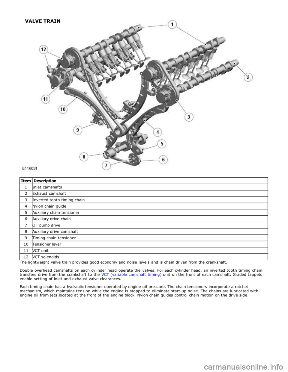
1 Inlet camshafts 2 Exhaust camshaft 3 Inverted tooth timing chain 4 Nylon chain guide 5 Auxiliary chain tensioner 6 Auxiliary drive chain 7 Oil pump drive 8 Auxiliary drive camshaft 9 Timing chain tensioner 10 Tensioner lever 11 VCT unit 12 VCT solenoids The lightweight valve train provides good economy and noise levels and is chain driven from the crankshaft.
Double overhead camshafts on each cylinder head operate the valves. For each cylinder head, an inverted tooth timing chain
transfers drive from the crankshaft to the VCT (variable camshaft timing) unit on the front of each camshaft. Graded tappets
enable setting of inlet and exhaust valve clearances.
Each timing chain has a hydraulic tensioner operated by engine oil pressure. The chain tensioners incorporate a ratchet
mechanism, which maintains tension while the engine is stopped to eliminate start-up noise. The chains are lubricated with
engine oil from jets located at the front of the engine block. Nylon chain guides control chain motion on the drive side. VALVE TRAIN