width JAGUAR XFR 2010 1.G Workshop Manual
[x] Cancel search | Manufacturer: JAGUAR, Model Year: 2010, Model line: XFR, Model: JAGUAR XFR 2010 1.GPages: 3039, PDF Size: 58.49 MB
Page 54 of 3039

Hydrofluorocarbon HFC High tension HT Hydrocarbon HC Idle Air Control IAC
Stepper motor driven device which varies the volume of air by-passing the
throttle to maintain the programmed idle speed Intake Air Temperature IAT Temperature of intake air Inertia Fuel Shut-off IFS
An inertia system that shuts off the fuel supply when activated by pre-determined force limits brought about by (e.g.) collision Input Shaft Speed ISS Indicates input shaft speed Key On, Engine Off KOEO Key On, Engine Running KOER Kilogram (mass) kg Kilogram (force) kgf Kilogram force per square
centimeter kgf/cm²
Kilometer km Kilometer per hour km/h Kilopascal kPa Kilovolt kV Knock Sensor KS
Sensor which detects the onset of detonation, and signals the ECM to
retard the ignition Liquid Crystal Display LCD
Optical digital display system, to which applied voltage varies the way the crystals reflect light, thereby modifying the display Lighting Control Module LCM Light Emitting Diode LED Low Tension LT
Primary circuit of the ignition system, linking the battery to the primary winding in the ignition coil Left-Hand LH Left-Hand Drive LHD Mass Air Flow MAF
System which provides information on the mass flow rate of the intake air
to the engine Manifold Absolute Pressure MAP Absolute pressure of the intake manifold air Manifold Absolute Pressure and Temperature MAPT
Malfunction Indicator Lamp MIL
A required on-board indicator to alert the driver of an emission related
malfunction Meter (measurement) m Metric (screw thread, e.g. M8) M Farad F Unit of electrical capacitance Millimeter mm Millimeter of mercury mmHg Millisecond ms Model year MY Newton N SI unit of force. 1 N = 0.2248 pounds force Newton Meter Nm SI unit of torque. Must not be confused with nm (nanometer) Negative Temperature
Coefficient NTC
Naturally aspirated N/A
Fuelling system using intake air at atmospheric pressure; not supercharged or turbocharged Noise, Vibration and Harshness NVH North American Specification NAS Vehicles for sale in the USA and Canadian markets On-Board Diagnostic OBD
A system that monitors some or all computer input and output control
signals. Signal(s) outside the pre-determined limits imply a fault in the system or a related system Oxides of Nitrogen Nox Oxygen Sensor O2S A sensor which detects oxygen content in the exhaust gases On-board Refuelling Vapour Recovery ORVR
Output State Control OSC Output Shaft Speed OSS Passenger Air Bag Deactivation PAD Pulsed Secondary Air Injection PAIR Passive Anti-Theft System PATS Positive Crankcase Ventilation PCV Parameter Identification PID
An index number referring to a parameter within a module without knowledge of its storage location Park/Neutral Position PNP Pulse Width Modulation PWM Programmable Electronic
Control Units System PECUS
Process whereby a common ECM is programmed on the production line to
suit the market requirements of a particular vehicle
Page 164 of 3039
Published: 18-Apr-2014
General Information - Diagnostic Trouble Code (DTC) Index V8 S/C 5.0L
Petrol, DTC: Engine Control Module (ECM)
Description and Operation
Engine Control Module (PCM) 5.0L SC V8 - AJ133
WARNING: Fuel injector voltage will reach 65 Volts during operation and have a high current requirement.
CAUTION: Diagnosis by substitution from a donor vehicle is NOT acceptable. Substitution of control modules does not
guarantee confirmation of a fault, and may also cause additional faults in the vehicle being tested and/or the donor vehicle
NOTES:
If the control module or a component is suspect and the vehicle remains under manufacturer warranty, refer to the
Warranty Policy and Procedures manual, or determine if any prior approval programme is in operation, prior to the installation
of a new module/component.
Generic scan tools may not read the codes listed, or may read only five digit codes. Match the five digits from the scan
tool to the first five digits of the seven digit code listed to identify the fault (the last two digits give additional information
read by the manufacturer-approved diagnostic system).
When performing electrical voltage or resistance tests, always use a digital multimeter (DMM) accurate to three decimal
places, and with an up-to-date calibration certificate. When testing resistance, always take the resistance of the DMM leads
into account.
Check and rectify basic faults before beginning diagnostic routines involving pinpoint tests.
If DTCs are recorded and, after performing the pinpoint tests, a fault is not present, an intermittent concern may be the
cause. Always check for loose connections and corroded terminals.
Check DDW for open campaigns. Refer to the corresponding bulletins and SSMs which may be valid for the specific
customer complaint and carry out the recommendations as required.
The table below lists all diagnostic trouble codes (DTCs) that could be logged in the electronic engine control module, for
additional diagnosis and testing information refer to the relevant diagnosis and testing section.
For additional information, refer to: Electronic Engine Controls (303-14 Electronic Engine Controls - V8 S/C 5.0L Petrol,
Diagnosis and Testing).
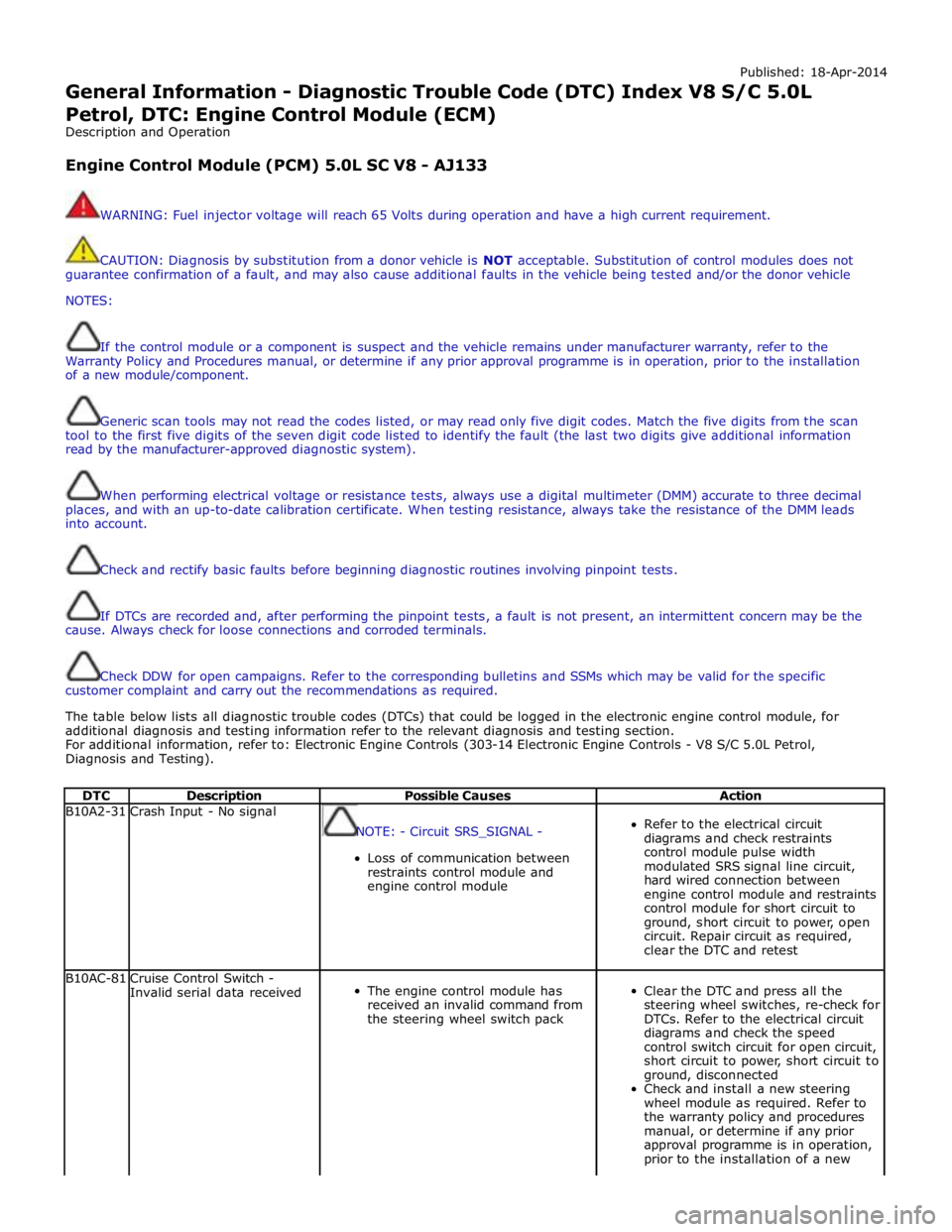
DTC Description Possible Causes Action B10A2-31 Crash Input - No signal
NOTE: - Circuit SRS_SIGNAL -
Loss of communication between
restraints control module and
engine control module
Refer to the electrical circuit
diagrams and check restraints
control module pulse width
modulated SRS signal line circuit,
hard wired connection between
engine control module and restraints
control module for short circuit to
ground, short circuit to power, open
circuit. Repair circuit as required,
clear the DTC and retest B10AC-81
Cruise Control Switch -
Invalid serial data received
The engine control module has
received an invalid command from
the steering wheel switch pack
Clear the DTC and press all the
steering wheel switches, re-check for
DTCs. Refer to the electrical circuit
diagrams and check the speed
control switch circuit for open circuit,
short circuit to power, short circuit to
ground, disconnected
Check and install a new steering
wheel module as required. Refer to
the warranty policy and procedures
manual, or determine if any prior
approval programme is in operation,
prior to the installation of a new
Page 727 of 3039
between moving components such as the steering wheel to steering column shroud.
Grunt (Squawk/Whoop)
Grunt is a 'honking' sound elicited when coming off one of the steering stops. Grunt is generally excited during parking
manoeuvres with a low to medium speed steering input.
Hiss (Swish)
Hiss or Valve Hiss is a high-frequency sound coming from the steering gear when the system is loaded. It is a rushing or
'swish' noise that doesn't change frequency with RPM. Hiss is the general noise generated by the flow of hydraulic fluid through
restrictions in the steering system. Restrictions include the rotary steering valve, power steering tubes, connectors, tuning
orifices, etc. Hiss can be air-borne and structure-borne, but the structure-borne path through the steering intermediate shaft is
usually dominant.
Moan (Groan)
Moan is the general structure-borne noise of the steering system. Moan is primarily transmitted to the driver via the body
structure through the pump mount, engine mounts, power steering lines and power steering brackets. On some vehicles, moan
is a loud humming noise, often present when the wheel is turned and the system is loaded. It may change frequency with
engine RPM and if the system is loaded or unloaded.
Steering Gear Knock (Steering Gear Slap)
CAUTION: DO NOT attempt to adjust the steering gear yoke. Failure to follow this instruction will invalidate the steering
gear warranty.
Steering gear knock is a rattle sound and steering wheel vibration caused by separation of the steering gear and pinion while
driving over bumps. It is a structure-borne noise transmitted through the intermediate shaft and column. Steering gear knock
can also be heard as a 'thump' or impact noise that occurs with the vehicle stationary when the steering wheel is released
from a loaded position and allowed to return to rest. Noise occurs with the engine on or off.
Rattles
Rattles are noises caused by knocking or hitting of components in the steering system. Steering rattles can occur in the engine
compartment, the suspension, or the passenger compartment. Rattles can be caused by loose components, movable and
flexible components, and improper clearances.
Squeaks/Scrapes
Squeaks/Scrapes are noises due to friction or component rubbing anywhere in the steering system. Squeaks/Scrapes have
appeared in steering linkages and joints, in column components and in column and steering wheel trim.
Weep
Weep is an air-borne noise, occasionally generated when turning the steering across lock at a constant rate. When present on
a vehicle the noise, once initiated can often be maintained across a large proportion of the available steering movement.
Whistle
Whistle is similar to hiss but is louder and of a higher frequency. It is also more of a pure tone noise than hiss. Whistle is
air-borne and is generated by a high flow rate of hydraulic fluid through a small restriction.
Zip
Zip noise is the air-borne noise generated by power steering pump cavitation when power steering fluid does not flow freely
through the suction hose from the reservoir to the pump. Zip primarily occurs during cold weather at start-up.
Steering System Vibrations and Harshness
Buzz
Buzz is a tactile rotary vibration felt in the steering wheel when steering inputs are slow. Buzz can also be called a grinding
feel and it is closely related to grunt and is caused by high system gain with low damping. Buzz is generally excited during
parking manoeuvres with low to medium speed steering input.
Buzz (Electrical)
A different steering buzz can be caused by pulse width modulated (PWM) electric actuators used in variable assist steering
systems. This buzz is felt by turning the ignition key to run without starting the engine and holding onto the steering wheel.
In extreme cases, the buzz can be felt with the engine running also.
Column/Steering Wheel Shake
Column shake is a low frequency vertical vibration excited by primary engine vibrations.
Nibble (Shimmy)
Page 859 of 3039
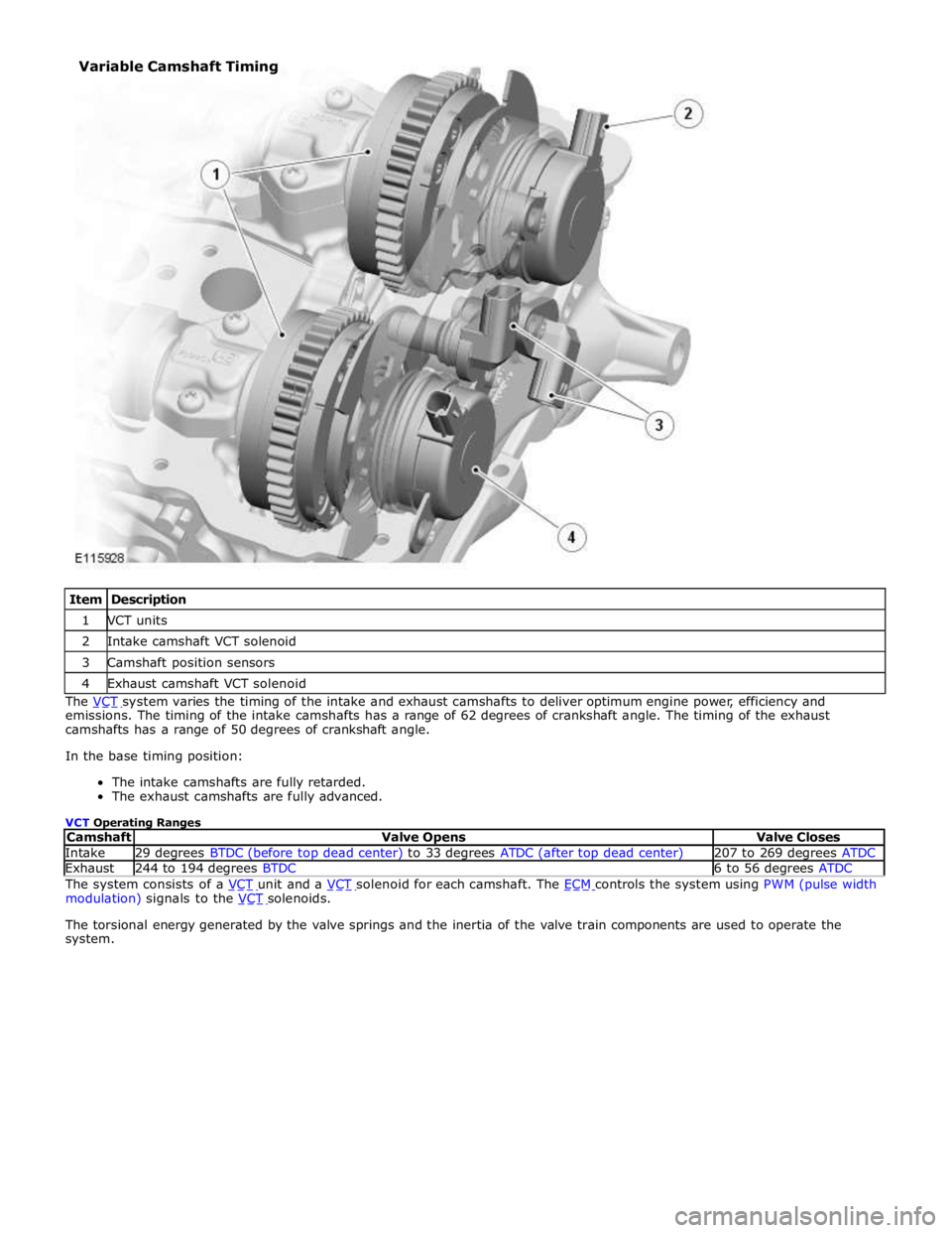
1 VCT units 2 Intake camshaft VCT solenoid 3 Camshaft position sensors 4 Exhaust camshaft VCT solenoid The VCT system varies the timing of the intake and exhaust camshafts to deliver optimum engine power, efficiency and emissions. The timing of the intake camshafts has a range of 62 degrees of crankshaft angle. The timing of the exhaust
camshafts has a range of 50 degrees of crankshaft angle.
In the base timing position:
The intake camshafts are fully retarded.
The exhaust camshafts are fully advanced.
VCT Operating Ranges
Camshaft Valve Opens Valve Closes Intake 29 degrees BTDC (before top dead center) to 33 degrees ATDC (after top dead center) 207 to 269 degrees ATDC Exhaust 244 to 194 degrees BTDC 6 to 56 degrees ATDC The system consists of a VCT unit and a VCT solenoid for each camshaft. The ECM controls the system using PWM (pulse width modulation) signals to the VCT solenoids.
The torsional energy generated by the valve springs and the inertia of the valve train components are used to operate the
system. Variable Camshaft Timing
Page 1114 of 3039
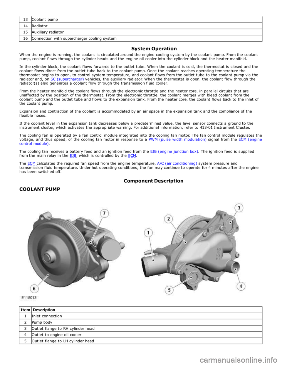
14 Radiator 15 Auxiliary radiator 16 Connection with supercharger cooling system
System Operation
When the engine is running, the coolant is circulated around the engine cooling system by the coolant pump. From the coolant
pump, coolant flows through the cylinder heads and the engine oil cooler into the cylinder block and the heater manifold.
In the cylinder block, the coolant flows forwards to the outlet tube. When the coolant is cold, the thermostat is closed and the
coolant flows direct from the outlet tube back to the coolant pump. Once the coolant reaches operating temperature the
thermostat begins to open, to control system temperature, and coolant flows from the outlet tube to the coolant pump via the
radiator and, on SC (supercharger) vehicles, the auxiliary radiator. When the thermostat is open, the coolant flow through the
radiator(s) also generates a coolant flow through the transmission fluid cooler.
From the heater manifold the coolant flows through the electronic throttle and the heater core, in parallel circuits that are
unaffected by the position of the thermostat. From the electronic throttle, the coolant merges with bleed coolant from the
coolant pump and the outlet tube and flows to the expansion tank. From the heater core, the coolant flows back to the inlet of
the coolant pump.
Expansion and contraction of the coolant is accommodated by an air space in the expansion tank and the compliance of the
flexible hoses.
If the coolant level in the expansion tank decreases below a predetermined value, the level sensor connects a ground to the
instrument cluster, which activates the appropriate warning. For additional information, refer to 413-01 Instrument Cluster.
The cooling fan is operated by a fan control module integrated into the cooling fan motor. The fan control module regulates the
voltage, and thus speed, of the cooling fan motor in response to a PWM (pulse width modulation) signal from the ECM (engine
control module).
The cooling fan receives a battery feed and an ignition feed from the EJB (engine junction box). The ignition feed is supplied
from the main relay in the EJB, which is controlled by the ECM.
The ECM calculates the required fan speed from the engine temperature, A/C (air conditioning) system pressure and transmission fluid temperature. Under hot operating conditions, the fan may continue to operate for 4 minutes after the engine
has been switched off.
COOLANT PUMP Component Description
Item Description 1 Inlet connection 2 Pump body 3 Outlet flange to RH cylinder head 4 Outlet to engine oil cooler 5 Outlet flange to LH cylinder head
Page 1348 of 3039
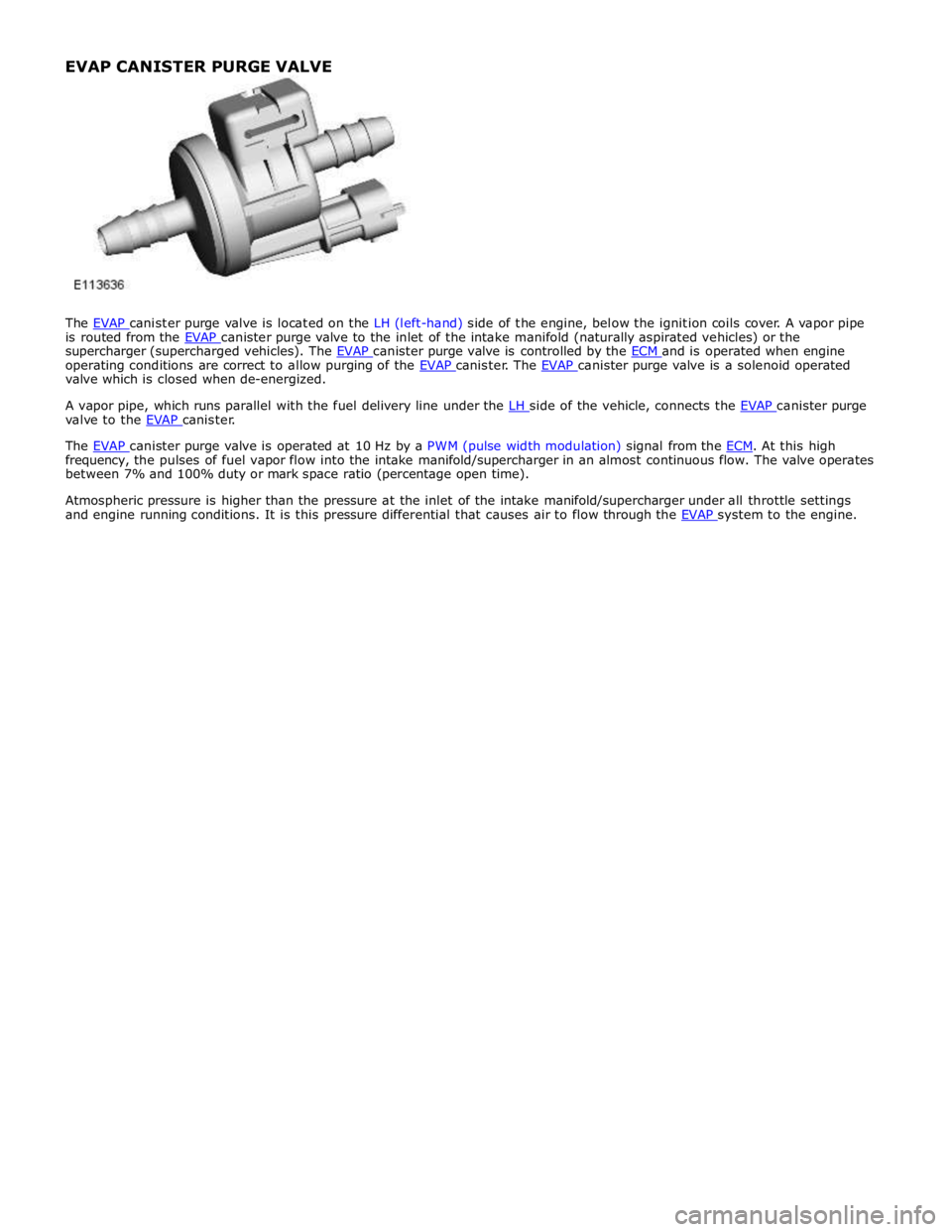
is routed from the EVAP canister purge valve to the inlet of the intake manifold (naturally aspirated vehicles) or the supercharger (supercharged vehicles). The EVAP canister purge valve is controlled by the ECM and is operated when engine operating conditions are correct to allow purging of the EVAP canister. The EVAP canister purge valve is a solenoid operated valve which is closed when de-energized.
A vapor pipe, which runs parallel with the fuel delivery line under the LH side of the vehicle, connects the EVAP canister purge valve to the EVAP canister.
The EVAP canister purge valve is operated at 10 Hz by a PWM (pulse width modulation) signal from the ECM. At this high frequency, the pulses of fuel vapor flow into the intake manifold/supercharger in an almost continuous flow. The valve operates
between 7% and 100% duty or mark space ratio (percentage open time).
Atmospheric pressure is higher than the pressure at the inlet of the intake manifold/supercharger under all throttle settings
and engine running conditions. It is this pressure differential that causes air to flow through the EVAP system to the engine. EVAP CANISTER PURGE VALVE
Page 1365 of 3039
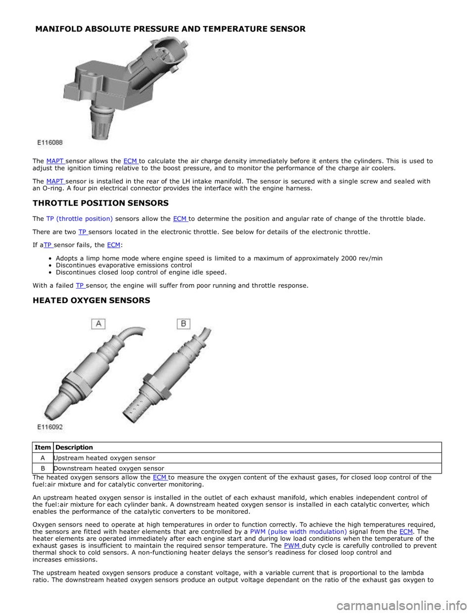
MANIFOLD ABSOLUTE PRESSURE AND TEMPERATURE SENSOR
The MAPT sensor allows the ECM to calculate the air charge density immediately before it enters the cylinders. This is used to adjust the ignition timing relative to the boost pressure, and to monitor the performance of the charge air coolers.
The MAPT sensor is installed in the rear of the LH intake manifold. The sensor is secured with a single screw and sealed with an O-ring. A four pin electrical connector provides the interface with the engine harness.
THROTTLE POSITION SENSORS
The TP (throttle position) sensors allow the ECM to determine the position and angular rate of change of the throttle blade. There are two TP sensors located in the electronic throttle. See below for details of the electronic throttle. If aTP sensor fails, the ECM:
Adopts a limp home mode where engine speed is limited to a maximum of approximately 2000 rev/min
Discontinues evaporative emissions control
Discontinues closed loop control of engine idle speed.
With a failed TP sensor, the engine will suffer from poor running and throttle response.
HEATED OXYGEN SENSORS
Item Description A Upstream heated oxygen sensor B Downstream heated oxygen sensor The heated oxygen sensors allow the ECM to measure the oxygen content of the exhaust gases, for closed loop control of the fuel:air mixture and for catalytic converter monitoring.
An upstream heated oxygen sensor is installed in the outlet of each exhaust manifold, which enables independent control of
the fuel:air mixture for each cylinder bank. A downstream heated oxygen sensor is installed in each catalytic converter, which
enables the performance of the catalytic converters to be monitored.
Oxygen sensors need to operate at high temperatures in order to function correctly. To achieve the high temperatures required,
the sensors are fitted with heater elements that are controlled by a PWM (pulse width modulation) signal from the ECM. The heater elements are operated immediately after each engine start and during low load conditions when the temperature of the
exhaust gases is insufficient to maintain the required sensor temperature. The PWM duty cycle is carefully controlled to prevent thermal shock to cold sensors. A non-functioning heater delays the sensor’s readiness for closed loop control and
increases emissions.
The upstream heated oxygen sensors produce a constant voltage, with a variable current that is proportional to the lambda
ratio. The downstream heated oxygen sensors produce an output voltage dependant on the ratio of the exhaust gas oxygen to
Page 1372 of 3039
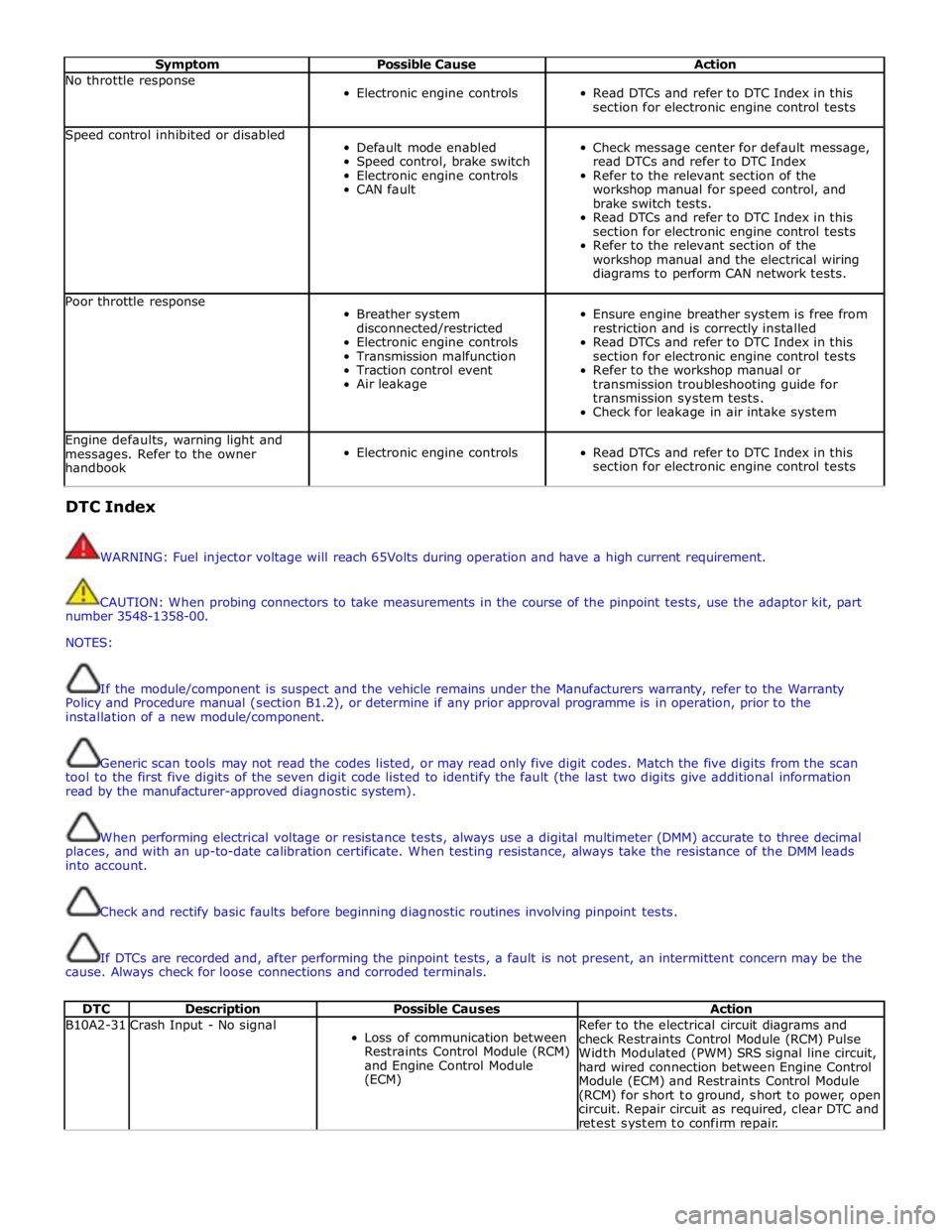
Symptom Possible Cause Action No throttle response
Electronic engine controls
Read DTCs and refer to DTC Index in this
section for electronic engine control tests Speed control inhibited or disabled
Default mode enabled
Speed control, brake switch
Electronic engine controls
CAN fault
Check message center for default message,
read DTCs and refer to DTC Index
Refer to the relevant section of the
workshop manual for speed control, and
brake switch tests.
Read DTCs and refer to DTC Index in this
section for electronic engine control tests
Refer to the relevant section of the
workshop manual and the electrical wiring
diagrams to perform CAN network tests. Poor throttle response
Breather system
disconnected/restricted
Electronic engine controls
Transmission malfunction
Traction control event
Air leakage
Ensure engine breather system is free from
restriction and is correctly installed
Read DTCs and refer to DTC Index in this
section for electronic engine control tests
Refer to the workshop manual or
transmission troubleshooting guide for
transmission system tests.
Check for leakage in air intake system Engine defaults, warning light and
messages. Refer to the owner
handbook
Electronic engine controls
Read DTCs and refer to DTC Index in this
section for electronic engine control tests DTC Index
WARNING: Fuel injector voltage will reach 65Volts during operation and have a high current requirement.
CAUTION: When probing connectors to take measurements in the course of the pinpoint tests, use the adaptor kit, part
number 3548-1358-00.
NOTES:
If the module/component is suspect and the vehicle remains under the Manufacturers warranty, refer to the Warranty
Policy and Procedure manual (section B1.2), or determine if any prior approval programme is in operation, prior to the
installation of a new module/component.
Generic scan tools may not read the codes listed, or may read only five digit codes. Match the five digits from the scan
tool to the first five digits of the seven digit code listed to identify the fault (the last two digits give additional information
read by the manufacturer-approved diagnostic system).
When performing electrical voltage or resistance tests, always use a digital multimeter (DMM) accurate to three decimal
places, and with an up-to-date calibration certificate. When testing resistance, always take the resistance of the DMM leads
into account.
Check and rectify basic faults before beginning diagnostic routines involving pinpoint tests.
If DTCs are recorded and, after performing the pinpoint tests, a fault is not present, an intermittent concern may be the
cause. Always check for loose connections and corroded terminals.
DTC Description Possible Causes Action B10A2-31 Crash Input - No signal
Loss of communication between
Restraints Control Module (RCM)
and Engine Control Module
(ECM) Refer to the electrical circuit diagrams and
check Restraints Control Module (RCM) Pulse
Width Modulated (PWM) SRS signal line circuit,
hard wired connection between Engine Control
Module (ECM) and Restraints Control Module
(RCM) for short to ground, short to power, open
circuit. Repair circuit as required, clear DTC and
retest system to confirm repair.
Page 1428 of 3039
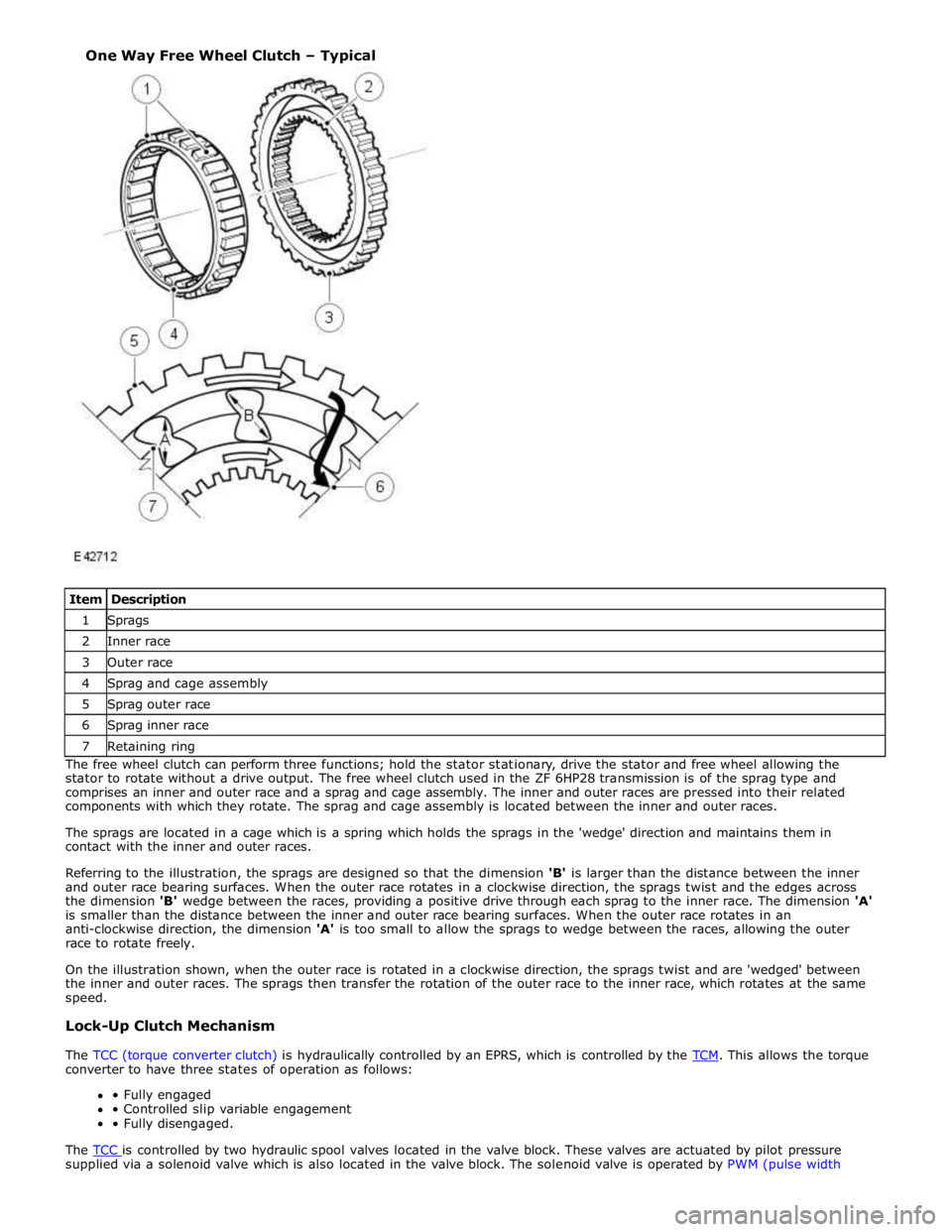
1 Sprags 2 Inner race 3 Outer race 4 Sprag and cage assembly 5 Sprag outer race 6 Sprag inner race 7 Retaining ring The free wheel clutch can perform three functions; hold the stator stationary, drive the stator and free wheel allowing the
stator to rotate without a drive output. The free wheel clutch used in the ZF 6HP28 transmission is of the sprag type and
comprises an inner and outer race and a sprag and cage assembly. The inner and outer races are pressed into their related
components with which they rotate. The sprag and cage assembly is located between the inner and outer races.
The sprags are located in a cage which is a spring which holds the sprags in the 'wedge' direction and maintains them in
contact with the inner and outer races.
Referring to the illustration, the sprags are designed so that the dimension 'B' is larger than the distance between the inner
and outer race bearing surfaces. When the outer race rotates in a clockwise direction, the sprags twist and the edges across
the dimension 'B' wedge between the races, providing a positive drive through each sprag to the inner race. The dimension 'A'
is smaller than the distance between the inner and outer race bearing surfaces. When the outer race rotates in an
anti-clockwise direction, the dimension 'A' is too small to allow the sprags to wedge between the races, allowing the outer
race to rotate freely.
On the illustration shown, when the outer race is rotated in a clockwise direction, the sprags twist and are 'wedged' between
the inner and outer races. The sprags then transfer the rotation of the outer race to the inner race, which rotates at the same
speed.
Lock-Up Clutch Mechanism
The TCC (torque converter clutch) is hydraulically controlled by an EPRS, which is controlled by the TCM. This allows the torque converter to have three states of operation as follows:
• Fully engaged
• Controlled slip variable engagement
• Fully disengaged.
The TCC is controlled by two hydraulic spool valves located in the valve block. These valves are actuated by pilot pressure supplied via a solenoid valve which is also located in the valve block. The solenoid valve is operated by PWM (pulse width One Way Free Wheel Clutch – Typical
Page 1584 of 3039

the flow and pressure supplied by controlling the operation of the fuel pump using a PWM (pulse width modulation) output. A
LP sensor is located in the fuel feed supply line to the engine and is monitored by the ECM for fuel pump control.
Two fuel level sensors are installed in either side of the saddle tank. The sensors are a MAPPS (magnetic passive position
sensor) which provide a variable resistance to ground for the output from the fuel gage.
The fuel system also incorporates an EVAP (evaporative emission) system which is part of the on-board refueling and vapor
recovery feature. The function and operation of the system is designed to meet EVAP requirements to minimize fuel vapor losses.