automatic transmission JAGUAR XJ 1994 2.G AJ16 Engine Manual
[x] Cancel search | Manufacturer: JAGUAR, Model Year: 1994, Model line: XJ, Model: JAGUAR XJ 1994 2.GPages: 73, PDF Size: 2.06 MB
Page 9 of 73
AJ16 Engine Service Manual
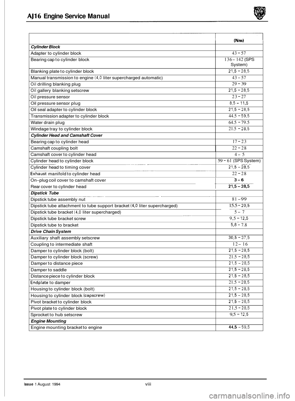
Cylinder Block
Adapter to cylinder block
Bearing cap to cylinder block
Blanking plate to cylinder block
Manual transmission to engine
(4,O liter supercharged automatic)
Oil drilling blanking plug
Oil gallery blanking setscrew
Oil pressure sensor
Oil pressure sensor plug
Oil seal adapter to cylinder block
Transmission adapter to cylinder block
Water drain plug
Windage tray to cylinder block
Cylinder Head and Camshaft Cover
Bearing cap to cylinder head
Camshaft coupling bolt
(Nm)
43 - 57
136
- 142 (SPS
System)
21,5 - 28,5
43 - 57
29
- 39
21,5 - 28,5
23 - 27
8,5- 11,5
21,5 - 28,5
44.5 - 59,5
64.5 - 79.5
21.5
- 28,5
17 - 23
22
- 28
Camshaft cover to cylinder head
- - . ~. Cylinder head to cylinder block
Cylinder head to timing cover -
______ ____ Exhaust manifold to cylinder head
On
-plug coil cover to camshaft cover
Rear cover to cylinder head
4-5
59 - 61 (SPS System) ~~ -. . - 21,5 - 28,5
22 - 28
_. . -.. ___ Dipstick
Tube
Dipstick tube assembly nut
Dipstick tube attachment to tube support bracket
(4,O liter supercharged)
__ Dipstick tube bracket (4,O liter supercharged)
Dipstick tube to bracket
Drive Chain System
Dipstick tube bracket screw
Auxiliary shaft assembly setscrew
Coupling to intermediate shaft
Damper to cylinder block (bolt)
Damper to cylinder block (screw)
Damper to distance piece
Damper to saddle
Distance piece to cylinder block
Endplate to damper
Housing to cylinder block (bolt)
Housing to cylinder block
(capscrew)
Pivot bracket to cylinder block
Pivot plate to cylinder block
Sprocket to hub setscrew
Engine Mounting
Engine mounting bracket to engine
Issue 1 August 1994 viii
81 -99
15.5 - 20,5
5-7
9,5
- 12,5
5%: 7.8
30,5 - 37,5
12-16
21,5 - 28,5
21.5 - 28,5
21,5 - 28,5
21,5 - 28,5
21,5 - 28,5
21.5 - 28,5
21,5 - 28,5
21,5 - 28,5
21,5 - 28,5
2 1,5 - 28,5
9,5 - 12,5
445 - 59,5
Page 14 of 73
AJ16 Engine Service Manual
SERVICE DATA
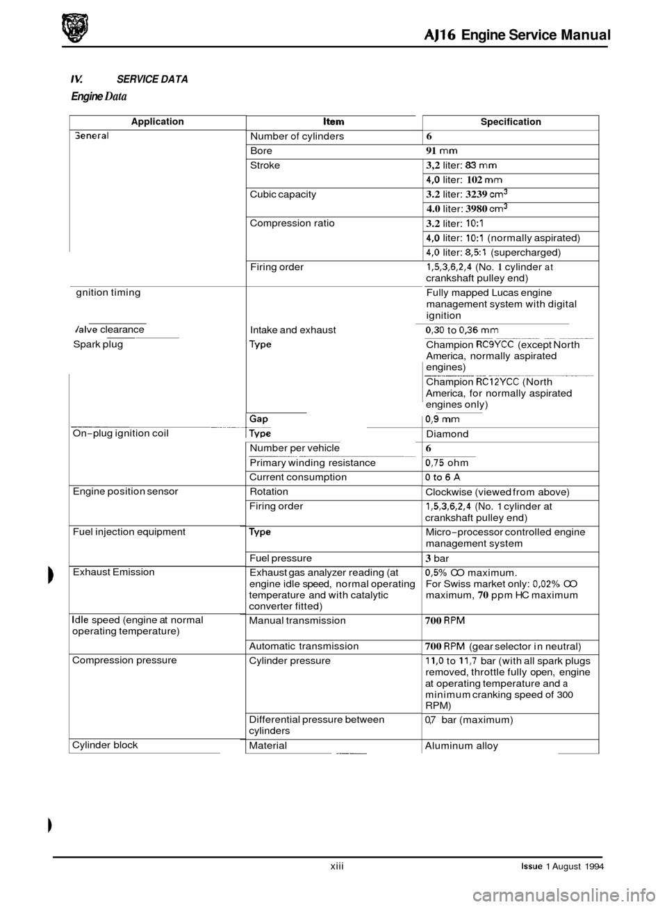
Engine Data
Application Item
Number of cylinders
Bore
Specification
Seneral 6
91
mm
Stroke 3,2 liter: 83 mm
4,O liter: 102 mm
3.2 liter: 3239 cm3
4.0 liter: 3980 cm3
Cubic capacity
Compression ratio
3.2 liter: 1O:l
4,O liter: 1O:l (normally aspirated)
4,O liter: 8,51 (supercharged)
1,5,3,6,2,4 (No. 1 cylinder at
crankshaft pulley end)
Fully mapped Lucas engine
management system with digital
ignition
Firing
order
gnition timing
0
0
0
Jalve clearance
Intake and exhaust 0,30 to 0,36 mm
Champion RCSYCC (except North
America, normally aspirated
engines)
Champion
RC12YCC (North
America, for normally aspirated
engines only)
__ ~ ~
--__ ~~
Spark
plug
0,9 mm
On-plug ignition coil
Diamond
Number per vehicle
Primary winding resistance
Current consumption ~ ~~
6
0,75 ohm
Oto6A
Clockwise
(viewed from above)
1,5,3,6,2,4 (No. 1 cylinder at
crankshaft pulley end)
-
Engine position sensor
Fuel injection equipment
Exhaust Emission Rotation
Firing order
Micro
-processor controlled engine
management system
Fuel pressure
Exhaust gas analyzer reading (at
engine idle speed, normal operating
temperature and with catalytic
converter fitted)
3 bar
0,5% CO maximum.
For Swiss market only:
0,02% CO
maximum,
70 ppm HC maximum
Idle speed (engine at normal
operating temperature) Manual transmission 700 RPM
Automatic
transmission 700 RPM (gear selector in neutral)
11,O to 11,7 bar (with all spark plugs
removed, throttle fully open, engine
at operating temperature and
a
minimum cranking speed of 300
RPM)
0,7 bar (maximum)
Compression pressure
Cylinder pressure
Differential pressure between
cylinders
Aluminum alloy
Cylinder block
. ___ Material
xiii
Issue 1 August 1994
Page 43 of 73
AJ16 Engine Service Manual
4.10 Crankshaft, Renew
SRO 12.21.33
m Remove the engine and transmission unit from the ve-
hicle, see Section 3.1 in the appropriate Vehicle Service
Manual.
Detach the transmission unit from the engine.
Fit the engine to a stand.
Remove the cylinder head, see Section 4.4.
. Remove the crankshaft damper pulley assembly, see Sec-
. Remove the oil pan , see Section 4.27.
Remove the oil pump, see Section 4.31.
. Remove the flywheel (Manual), see Section 4.15, or re-
. Remove the timing cover.
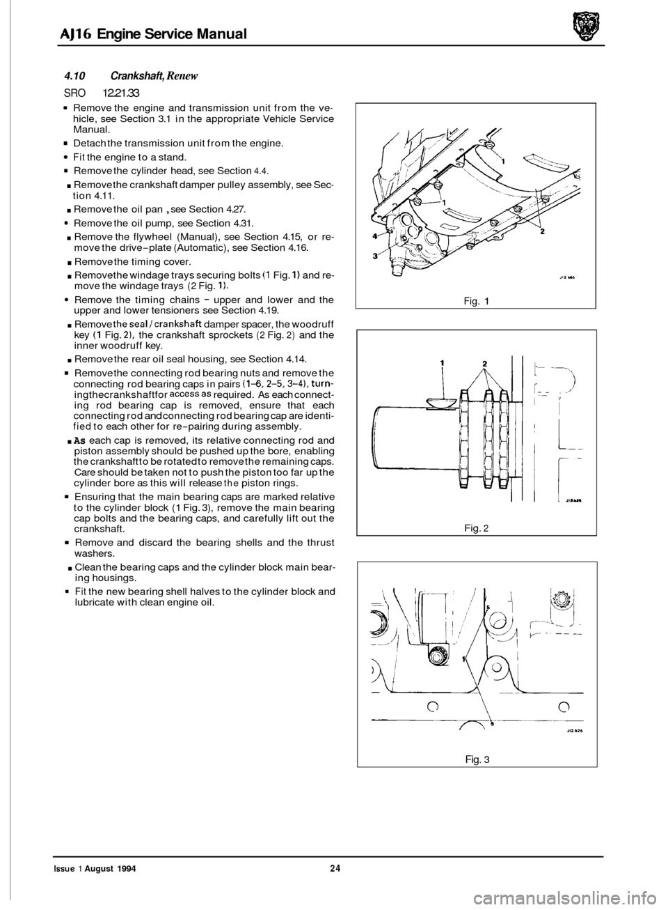
. Remove the windage trays securing bolts (1 Fig. 1) and re- move the windage trays (2 Fig. 1).
Remove the timing chains - upper and lower and the
upper and lower tensioners see Section 4.19.
. Remove theseal/crankshaft damper spacer, the woodruff
key (1 Fig. 21, the crankshaft sprockets (2 Fig. 2) and the
inner woodruff key.
tion
4.11.
move the drive
-plate (Automatic), see Section 4.16.
. Remove the rear oil seal housing, see Section 4.14.
Remove the connecting rod bearing nuts and remove the
connecting rod bearing caps in pairs
(1-6,2-5,3-4), turn- ingthecrankshaftfor accessas required. As each connect- ing rod bearing cap is removed, ensure that each
connecting rod and connecting rod bearing cap are identi- fied to each other for re-pairing during assembly.
. As each cap is removed, its relative connecting rod and
piston assembly should be pushed up the bore, enabling
the crankshaft to be rotated to remove the remaining caps.
Care should be taken not to push the piston too far up the
cylinder bore as this will release
the piston rings.
Ensuring that the main bearing caps are marked relative
to the cylinder block (1 Fig. 3), remove the main bearing
cap bolts and the bearing caps, and carefully lift out the
crankshaft.
Remove and discard the bearing shells and the thrust
washers.
. Clean the bearing caps and the cylinder block main bear- ing housings.
Fit the new bearing shell halves to the cylinder block and
lubricate with clean engine oil.
Fig. 1
!- ,1101,
Fig. 2
Fig. 3
Issue 1 August 1994 24
Page 44 of 73
AJ16 Engine Service Manual
1 Clean and polish the crankshaft journals, lubricate and
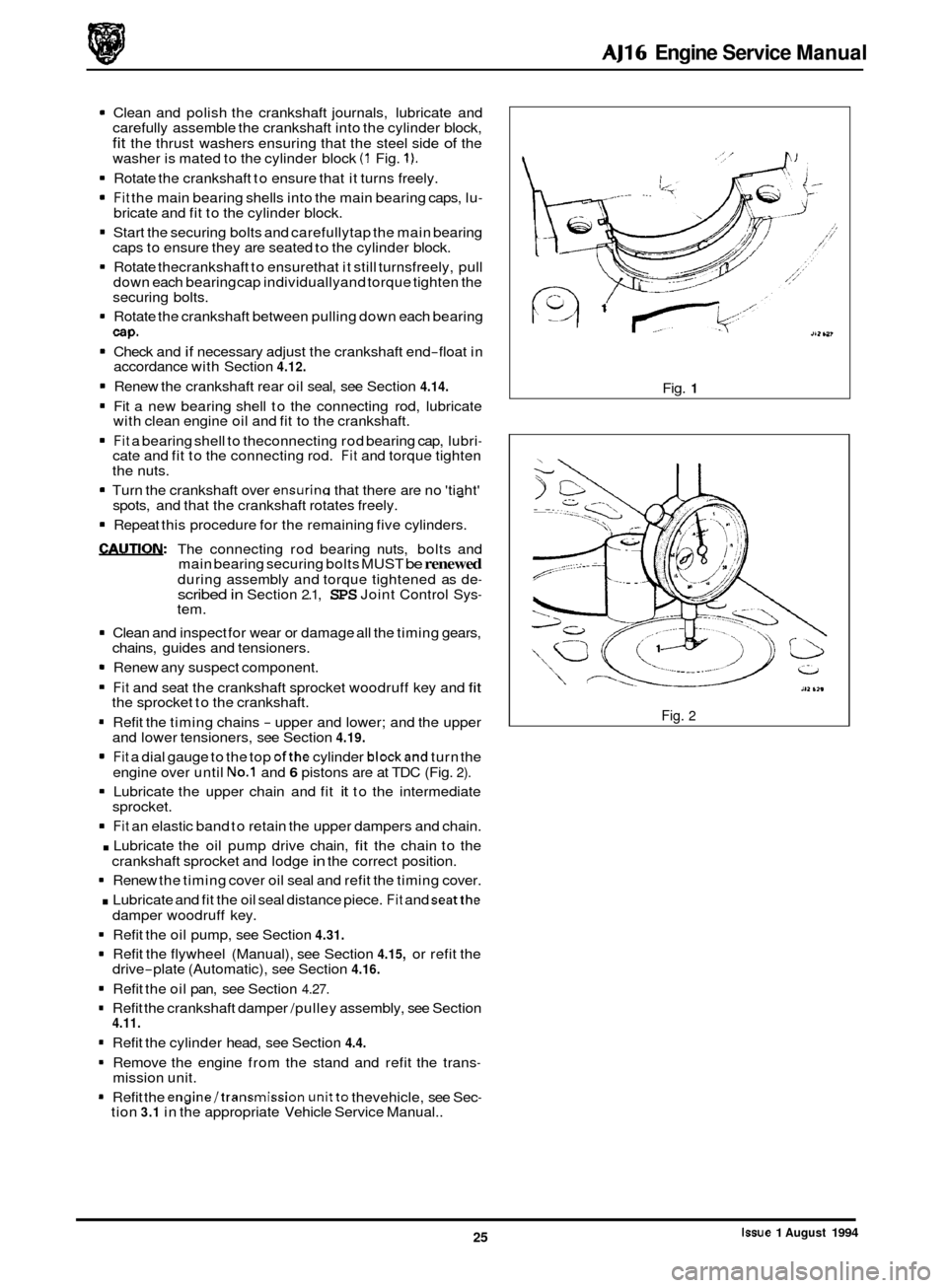
carefully assemble the crankshaft into the cylinder block,
fit the thrust washers ensuring that the steel side of the
washer is mated to the cylinder block (1 Fig. 1).
1 Rotate the crankshaft to ensure that it turns freely.
1 Fit the main bearing shells into the main bearing caps, lu- bricate and fit to the cylinder block.
1 Start the securing bolts and carefullytap the main bearing
caps to ensure they are seated to the cylinder block.
1 Rotate thecrankshaft to ensurethat it still turnsfreely, pull
down each bearing cap individuallyand torque tighten the
securing bolts.
1 Rotate the crankshaft between pulling down each bearing
cap.
1 Check and if necessary adjust the crankshaft end-float in
accordance with Section 4.12.
1 Renew the crankshaft rear oil seal, see Section 4.14.
1 Fit a new bearing shell to the connecting rod, lubricate
1 Fit a bearing shell to theconnecting rod bearing cap, lubri-
with clean engine oil and fit to the crankshaft.
cate and fit to the connecting rod.
Fit and torque tighten
1 Turn the crankshaft over ensuring that there are no 'tiaht'
the nuts.
spots, and that the crankshaft rotates freely.
-
1 Repeat this procedure for the remaining five cylinders.
WUTION: The connecting rod bearing nuts, bolts and
main bearing securing bolts MUST be renewed during assembly and torque tightened as de- scribed in Section 2.1, SPS Joint Control Sys- tem.
1 Clean and inspect for wear or damage all the timing gears,
chains, guides and tensioners.
1 Renew any suspect component.
1 Fit and seat the crankshaft sprocket woodruff key and fit the sprocket to the crankshaft.
1 Refit the timing chains - upper and lower; and the upper
and lower tensioners, see Section 4.19.
1 Fit a dial gauge to the top ofthe cylinder blockand turn the
engine over until No.1 and 6 pistons are at TDC (Fig. 2).
1 Lubricate the upper chain and fit it to the intermediate
sprocket.
0 1 Fit an elastic band to retain the upper dampers and chain.
. Lubricate the oil pump drive chain, fit the chain to the
crankshaft sprocket and lodge in the correct position.
1 Renew the timing cover oil seal and refit the timing cover.
. Lubricate and fit the oil seal distance piece. Fit and seatthe
1 Refit the oil pump, see Section 4.31.
1 Refit the flywheel (Manual), see Section 4.15, or refit the
1 Refit the oil pan, see Section 4.27.
1 Refit the crankshaft damper /pulley assembly, see Section
1 Refit the cylinder head, see Section 4.4.
1 Remove the engine from the stand and refit the trans-
1 Refit the engine/transmission unitto thevehicle, see Sec-
damper woodruff key.
drive
-plate (Automatic), see Section 4.16.
4.11.
mission unit.
tion
3.1 in the appropriate Vehicle Service Manual.. Fig.
1
Fig. 2
Issue 1 August 1994 25
Page 48 of 73
AJ16 Engine Service Manual
4.14 Crankshaft Rear Oil Seal, Renew
SRO 12.21.20
Remove the flywheel (Manual), see Section 4.15, or the
Remove the transmission adapter securing bolts and re-
Carefully remove the old oil seal from the adapter, clean
CAUTION: Do not remove the plastic ‘0 ring protector
from the new seal prior to fitting to the adapter.
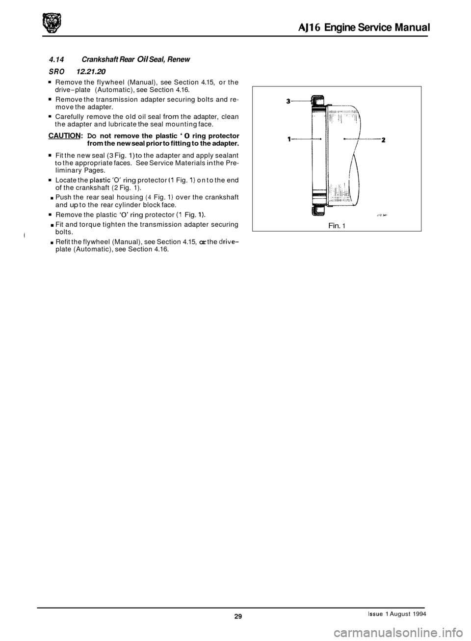
Fit the new seal (3 Fig. 1) to the adapter and apply sealant to the appropriate faces. See Service Materials in the Pre- liminary Pages.
Locate the plastic’o’ ring protector (1 Fig. 1) on to the end of the crankshaft (2 Fig. 1).
. Push the rear seal housing (4 Fig. 1) over the crankshaft
and
up to the rear cylinder block face.
Remove the plastic ‘0’ ring protector (1 Fig. 1).
. Fit and torque tighten the transmission adapter securing
drive
-plate
(Automatic), see Section 4.16.
move the adapter.
the adapter and lubricate
the seal mounting face.
bolts.
. Refit the flywheel (Manual), see Section 4.15, or the drive- plate (Automatic), see Section 4.16.
Fin. 1
Issue 1 August 1994 29
Page 51 of 73
AJ16 Engine Service Manual
4.17 Engine Rear/ Transmission Adapter Plate, Renew
SRO 12.53.03
1 Remove the engine flywheel (Manual), see Section 4.1 5, or
the engine drive
-plate (Automatic), see Section 4.16.
Remove the lower bolt securing the starter motor and re-
position the starter motor away from the adapter plate.
1 Remove the adapter plate securing bolts and remove the
adapter plate.
* Remove the dowel pegs and blanking plugs from the
adapter plate.
m Discard the adapter plate.
1 Fit the blanking plugs and dowel pegs to the new adapter
. Fit the assembly to the rear of the engine and torque
. Re-position the starter motor to the adapter plate and se-
m Refittheengineflywheel (Manual),see Section 4.15, orthe
plate.
tighten the securing bolts.
cure with the lower bolt.
engine drive
-plate (Automatic), see Section 4.16.
Issue 1 August 1994 32