sensor JAGUAR XJ 2004 X350 / 3.G User Guide
[x] Cancel search | Manufacturer: JAGUAR, Model Year: 2004, Model line: XJ, Model: JAGUAR XJ 2004 X350 / 3.GPages: 227, PDF Size: 4.22 MB
Page 106 of 227
On the Road 4 - 35
Park Distance Control
Caution: It remains the driver’s
responsibility to detect obstacles and
estimate the car’s distance from
them. Some overhanging objects,
barriers, thin obstructions or painted
surfaces which could possibly cause
damage to the vehicle may not be
detected by the system. Always be
vigilant when reversing.
Park distance control is always
automatically switched on when the
ignition is turned on.
Caution:
1. If, for example, you are driving into a confined space such as a
home garage, the outer sensors
will detect the side walls and after
3 seconds will switch the tone off.
However, as movement
continues, the inner sensors will
eventually detect the rear wall
and will start the tone again.
2. The sensors are not active when the gear selector is in neutral,
therefore, take care if moving the
vehicle as the tone will not be
heard.
3. Do not clean the sensors with abrasive or sharp objects. Note:
1. For reliable operation, the sensors in
the front (if fitted) and rear bumpers
should be kept free from frost, ice and
grime.
2. When using a high pressure spray the sensors should only be sprayed briefly
and at least 8 inches (20 cm) distance
from the sensors.
3. The front parking aid may sound spurious tones if it detects a frequency
tone using the same band as the
sensors.
Rear Park Distance Control
When reverse gear is selected and
ignition is on, rear park distance control
automatically provides an audible
proximity warning (to the nearest
detected obstacle) when reversing the
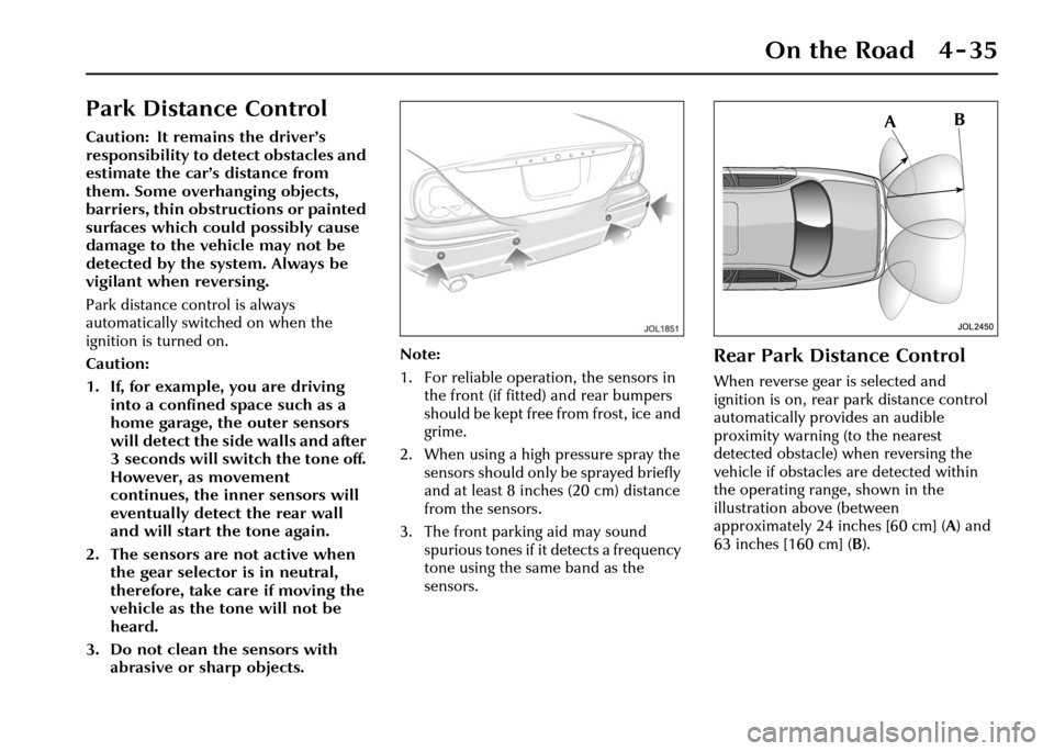
vehicle if obstacles are detected within
the operating range, shown in the
illustration above (between
approximately 24 inches [60 cm] ( A) and
63 inches [160 cm] ( B).
Page 107 of 227
4-36 On the Road
Front and Rear Park Distance
Control
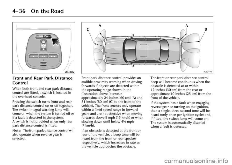
When both front and rear park distance
control are fitted, a switch is located in
the overhead console.
Pressing the switch turns front and rear
park distance control on or off together.
The switch integral warning lamp will
come on when the system is turned off or
if a fault is detected in the system.
A switch is not provided when only rear
park distance control is fitted.
Note: The front park distance control will
also operate when reverse gear is
selected. Front park distance control provides an
audible proximity warning when driving
forwards if objects are detected within
the operating range shown in the
illustration above (between
approximately 24 inches [60 cm] (
A) and
31 inches [80 cm] (C ) to the front of the
vehicle). The front sensors only operate
within a fixed speed range in forward
gears and are not effective when moving
forwards above 9mph (15km/h) or when
slowing down until below 4½ mph
(7 km/h).
If an obstacle is detected at the front or
rear of the vehicle, a beep tone will be
heard from the front or rear speaker
respectively, which increases in rate as
the vehicle approaches the obstacle. The front or rear park distance control
beep will become co
ntinuous when the
obstacle is detected at or within
12 inches (30 cm) from the rear or
approximate 10 inches (25 cm) from the
front of the vehicle.
If the system has a fault when engaging
reverse gear or turning on the ignition,
then a single, three second tone will be
heard (only once per ignition cycle) and,
if fitted, the switch lamp will come on.
The system is automatically disabled
when a fault is detected.
Page 122 of 227
On the Road 4 - 51
Adaptive Cruise Control (ACC)
(Where fitted)
The adaptive cruise control system is designed to aid the driver
to maintain a gap from the vehicle ahead or a set road speed if
there is no slower vehicle ahead. The system is intended to
provide enhanced operation of th e vehicle when following other
vehicles which are in the same lane and travelling in the same
direction.
!WARNING:
Adaptive cruise control is not a collision warning or
avoidance system. Additionally , adaptive cruise control
will not detect:
1. Stationary or slow moving vehicles below 6 mph (10 km/h).
2. Pedestrians or objects in the roadway.
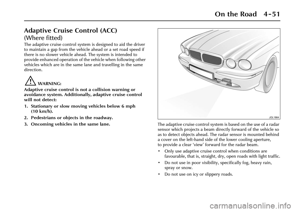
3. Oncoming vehicles in the same lane. The adaptive cruise control system is based on the use of a radar
sensor which projects a beam directly forward of the vehicle so
as to detect objects ahead. Th e radar sensor is mounted behind
a cover on the left-hand side of the lower cooling aperture,
to provide a clear ‘view’ forward for the radar beam.
• Only use adaptive cruise control when conditions are favourable, that is, straight, dry, open roads with light traffic.
• Do not use in poor visibility, specifically fog, heavy rain,
spray or snow.
• Do not use on icy or slippery roads.
Page 123 of 227
4-52 On the Road
• It is the drivers responsibility to stay alert, drive safely and be in control of
the vehicle at all times.
• Keep the front of the vehicle free from dirt, metal badges or objects,
including vehicle front protectors,
which may prevent the sensor from
operating.
• Do not use ACC when entering or leaving a motorway.
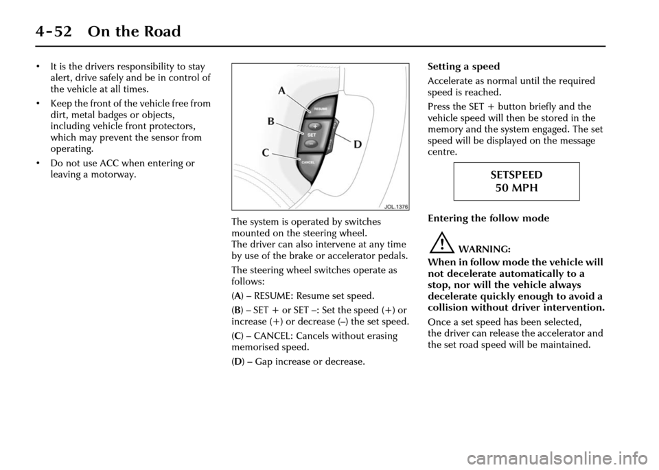
The system is operated by switches
mounted on the steering wheel.
The driver can also intervene at any time
by use of the brake or accelerator pedals.
The steering wheel switches operate as
follows:
(A ) – RESUME: Resume set speed.
( B )– SET+ or SET–: Setthe speed(+) or
increase (+) or decrease (–) the set speed.
( C ) – CANCEL: Cancels without erasing
memorised speed.
( D ) – Gap increase or decrease. Setting a speed
Accelerate as normal
until the required
speed is reached.
Press the SET + butto n briefly and the
vehicle speed will then be stored in the
memory and the system engaged. The set
speed will be displayed on the message
centre.
Entering the follow mode
!WARNING:
When in follow mode the vehicle will
not decelerate automatically to a
stop, nor will the vehicle always
decelerate quickly enough to avoid a
collision without driver intervention.
Once a set speed has been selected,
the driver can release the accelerator and
the set road speed will be maintained.
SETSPEED 50 MPH
Page 126 of 227
On the Road 4 - 55
Forward alert
Limited detection and warning of objects
ahead is provided during ACC operation
by the ACC ‘DRIVER INTERVENE’
warning.
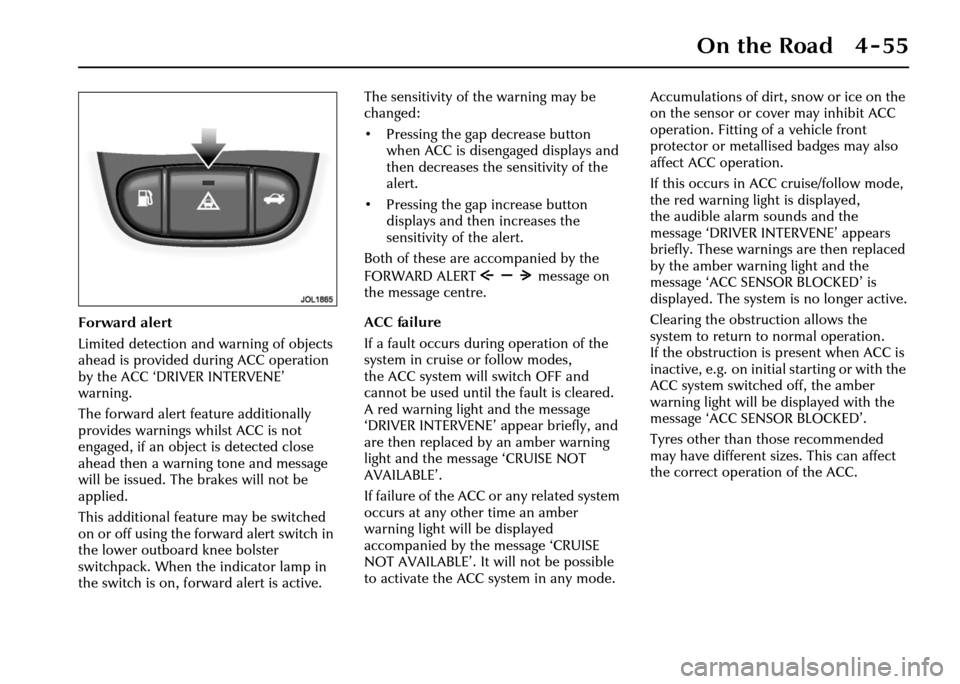
The forward alert feature additionally
provides warnings whilst ACC is not
engaged, if an object is detected close
ahead then a warning tone and message
will be issued. The brakes will not be
applied.
This additional feature may be switched
on or off using the forward alert switch in
the lower outboard knee bolster
switchpack. When the indicator lamp in
the switch is on, forward alert is active.The sensitivity of the warning may be
changed:
• Pressing the gap decrease button
when ACC is disengaged displays and
then decreases the sensitivity of the
alert.
• Pressing the gap increase button displays and then increases the
sensitivity of the alert.
Both of these are accompanied by the
FORWARD ALERT message on
the message centre.
ACC failure
If a fault occurs during operation of the
system in cruise or follow modes,
the ACC system will switch OFF and
cannot be used until the fault is cleared.
A red warning light and the message
‘DRIVER INTERVENE’ appear briefly, and
are then replaced by an amber warning
light and the message ‘CRUISE NOT
AVAILABLE’.
If failure of the ACC or any related system
occurs at any other time an amber
warning light will be displayed
accompanied by th e message ‘CRUISE
NOT AVAILABLE’. It will not be possible
to activate the ACC system in any mode. Accumulations of dirt, snow or ice on the
on the sensor or cover may inhibit ACC
operation. Fitting of a vehicle front
protector or metallis
ed badges may also
affect ACC operation.
If this occurs in ACC cruise/follow mode,
the red warning light is displayed,
the audible alarm sounds and the
message ‘DRIVER INTERVENE’ appears
briefly. These warnings are then replaced
by the amber warning light and the
message ‘ACC SENSOR BLOCKED’ is
displayed. The system is no longer active.
Clearing the obstruction allows the
system to return to normal operation.
If the obstruction is present when ACC is
inactive, e.g. on initial starting or with the
ACC system switched off, the amber
warning light will be displayed with the
message ‘ACC SENSOR BLOCKED’.
Tyres other than those recommended
may have different sizes. This can affect
the correct operation of the ACC.
Page 142 of 227
Climate Control 5 - 3
5 Climate Control
Introduction
The cabin is supplied with filtered air
from a fully automatic electronic climate
control system with manual overrides.
Two systems are available:
• A two zone system which allows the front occupants to set individual
temperatures for the left and right
sides of the interior.
• A four zone system which allows front and rear occupants to set individual
temperatures, i.e. two front zones and
two rear zones.
Occupant controls
The main climate control panel is located
in the centre console above the radio and
audio controls. There are two types of
control panel for either two or four zone
systems:
• A dedicated control panel with LCD (liquid crystal display) screen
(see page 5 - 6).
• A multi-function touch control and display unit shared with navigation
and other systems. Where this control
unit is fitted, refer to the Jaguar
Touch-screen Handbook for the
detailed operating instructions. Where the four zone climate control
system is fitted, an additional control/
display panel for rear passenger use is
located at the rear of the centre console,
between the front seats.
Voice control
The climate control system may also be
operated by spoken commands if the
optional voice activation system is fitted.
For full information on the use of this
system refer to the JaguarVoice
Handbook.
Recommended Operation
Automatic climate control
Automatic climate control provides
efficient regulation of the vehicle
environment without constant
adjustments from the occupant.
Sensors inside the vehicle monitor
temperature, humidity and direct
sunlight. In response, the electronic
control system automatically adjusts the
heat input, blower speed, air intake and
airflow distribution so as to maintain the
selected temperature(s) and reduce
misting.
Automatic operation provides optimum
comfort under most driving conditions. It is recommended that automatic
control (AUTO) is selected as the
normal operating mode.
Use of air conditioning
Air conditioning is an integral part of the
climate control system, providing cooled
and dehumidified
air for occupant
comfort; the dry airflow is also effective
in preventing misting of the windows.
While the air conditioner can be
manually switched off, it is recommended
that it is used in all climatic conditions
throughout the year, preferably in AUTO
mode.
Close all windows and the sunroof when
the air conditioning is on to ensure
satisfactory operation.
Use of air recirculation
The air conditioner/heater system is
supplied with fresh air via an intake flap.
Closing the flap causes the air inside the
vehicle to be recirculated. This helps to
prevent unpleasant odours from being
drawn into the vehicle and also to
improve the performance of the air
conditioner in very hot conditions.
However, the use of recirculated air will
cause screen misting after a short period
and should only be used as necessary.
Page 143 of 227
5 - 4 Climate Control
In AUTO mode, the air intake flap is
controlled automatically. If required,
air recirculation may be manually
selected for either a short or indefinite
period.
Air Recirculation
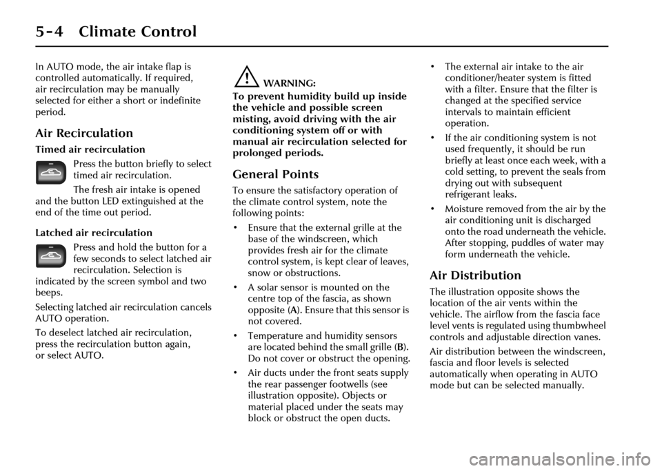
Timed air recirculationPress the button briefly to select
timed air recirculation.
The fresh air intake is opened
and the button LED extinguished at the
end of the time out period.
Latched air re circulation
Press and hold the button for a
few seconds to select latched air
recirculation. Selection is
indicated by the scre en symbol and two
beeps.
Selecting latched air recirculation cancels
AUTO operation.
To deselect latched air recirculation,
press the recirculat ion button again,
or select AUTO.
!WARNING:
To prevent humidity build up inside
the vehicle and possible screen
misting, avoid driving with the air
conditioning system off or with
manual air recirculation selected for
prolonged periods.
General Points
To ensure the satisfactory operation of
the climate control system, note the
following points:
• Ensure that the external grille at the base of the windscreen, which
provides fresh air for the climate
control system, is kept clear of leaves,
snow or obstructions.
• A solar sensor is mounted on the centre top of the fascia, as shown
opposite ( A) . E n s u r e t h a t this sensor is
not covered.
• Temperature and humidity sensors are located behind the small grille ( B).
Do not cover or obstruct the opening.
• Air ducts under the front seats supply the rear passenger footwells (see
illustration opposite). Objects or
material placed under the seats may
block or obstruct the open ducts. • The external air intake to the air
conditioner/heater system is fitted
with a filter. Ensure that the filter is
changed at the specified service
intervals to maintain efficient
operation.
• If the air conditioning system is not used frequently, it should be run
briefly at least once each week, with a
cold setting, to prevent the seals from
drying out with subsequent
refrigerant leaks.
• Moisture removed from the air by the air conditioning unit is discharged
onto the road underneath the vehicle.
After stopping, puddles of water may
form underneath the vehicle.
Air Distribution
The illustration opposite shows the
location of the air vents within the
vehicle. The airflow from the fascia face
level vents is regulated using thumbwheel
controls and adjustable direction vanes.
Air distribution between the windscreen,
fascia and floor levels is selected
automatically when operating in AUTO
mode but can be selected manually.
Page 148 of 227
Climate Control 5 - 9
Manual Air Distribution
Air distribution is automatically
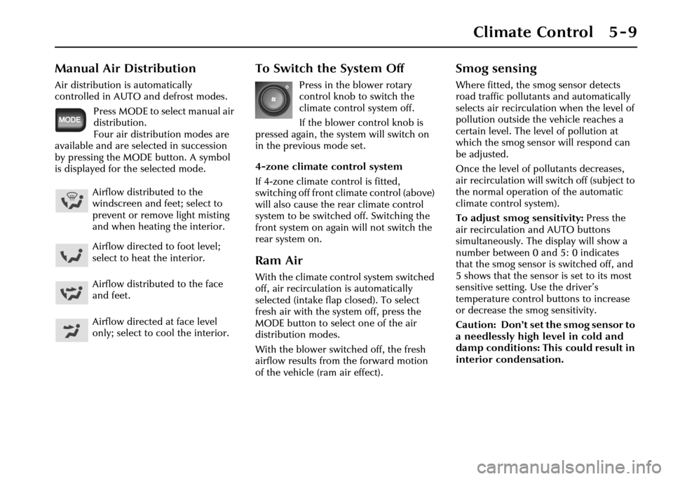
controlled in AUTO and defrost modes.Press MODE to select manual air
distribution.
Four air distribution modes are
available and are selected in succession
by pressing the MODE button. A symbol
is displayed for the selected mode.
To Switch the System Off
Press in the blower rotary
control knob to switch the
climate control system off.
If the blower control knob is
pressed again, the system will switch on
in the previous mode set.
4-zone climate control system
If 4-zone climate control is fitted,
switching off front climate control (above)
will also cause the rear climate control
system to be switched off. Switching the
front system on again will not switch the
rear system on.
Ram Air
With the climate control system switched
off, air recirculation is automatically
selected (intake flap closed). To select
fresh air with the system off, press the
MODE button to select one of the air
distribution modes.
With the blower switched off, the fresh
airflow results from the forward motion
of the vehicle (ram air effect).
Smog sensing
Where fitted, the smog sensor detects
road traffic pollutants and automatically
selects air recirculation when the level of
pollution outside the vehicle reaches a
certain level. The level of pollution at
which the smog sensor will respond can
be adjusted.
Once the level of pollutants decreases,
air recirculation will switch off (subject to
the normal operation of the automatic
climate control system).
To adjust smog sensitivity: Press the
air recirculation and AUTO buttons
simultaneously. The display will show a
number between 0 and 5: 0 indicates
that the smog sensor is switched off, and
5 shows that the sensor is set to its most
sensitive setting. Use the driver’s
temperature control bu ttons to increase
or decrease the smog sensitivity.
Caution: Don’t set the smog sensor to
a needlessly high level in cold and
damp conditions: This could result in
interior condensation.
Airflow distributed to the
windscreen and feet; select to
prevent or remove light misting
and when heating the interior.
Airflow directed to foot level;
select to heat the interior.
Airflow distributed to the face
and feet.
Airflow directed at face level
only; select to cool the interior.
Page 176 of 227
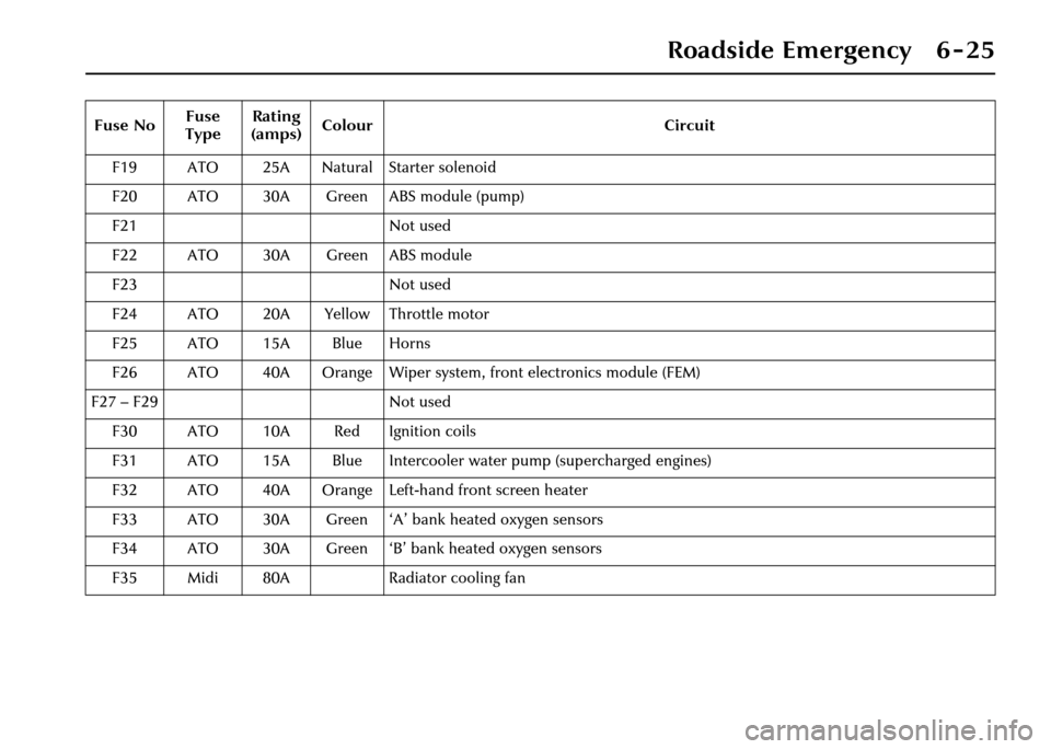
Roadside Emergency 6 - 25
F19 ATO 25A Natural Starter solenoid
F20 ATO 30A Green ABS module (pump)
F21 Not used
F22 ATO 30A Green ABS module
F23 Not used
F24 ATO 20A Yellow Throttle motor
F25 ATO 15A Blue Horns
F26 ATO 40A Orange Wiper system, front electronics module (FEM)
F27 – F29 Not used F30 ATO 10A Red Ignition coils
F31 ATO 15A Blue Intercooler water pump (supercharged engines)
F32 ATO 40A Orange Left-hand front screen heater
F33 ATO 30A Green ‘A’ bank heated oxygen sensors
F34 ATO 30A Green ‘B’ bank heated oxygen sensors
F35 Midi 80A Radiator cooling fan
Fuse No
Fuse
Type Rating
(amps) Colour Circuit
Page 177 of 227
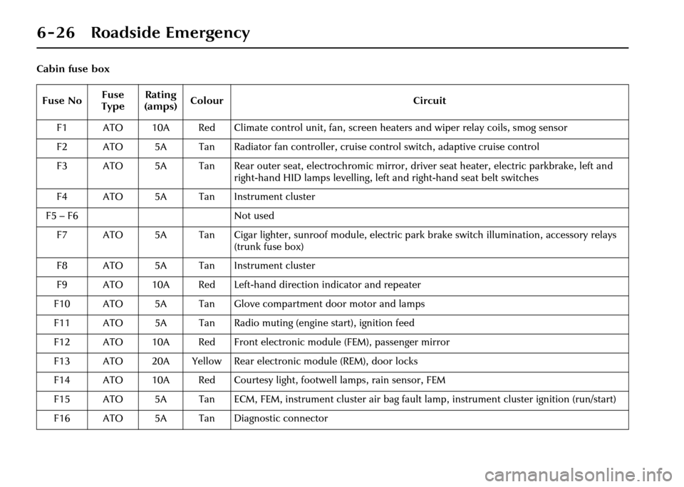
6 - 26 Roadside Emergency
Cabin fuse boxFuse No Fuse
Type Rating
(amps) Colour
Circuit
F1 ATO 10A Red Climate control unit, fan, screen heaters and wiper relay coils, smog sensor
F2 ATO 5A Tan Radiator fan controller, cruise control switch, adaptive cruise control
F3 ATO 5A Tan Rear outer seat, electrochromic mirror, driver seat heater, electric parkbrake, left and right-hand HID lamps levelling, left and right-hand seat belt switches
F4 ATO 5A Tan Instrument cluster
F5 – F6 Not used
F7 ATO 5A Tan Cigar lighter, sunroof module, electric park brake switch illumination, accessory relays (trunk fuse box)
F8 ATO 5A Tan Instrument cluster
F9 ATO 10A Red Left-hand direction indicator and repeater
F10 ATO 5A Tan Glove compartm ent door motor and lamps
F11 ATO 5A Tan Radio muting (engine start), ignition feed
F12 ATO 10A Red Front electronic module (FEM), passenger mirror
F13 ATO 20A Yellow Rear electronic module (REM), door locks
F14 ATO 10A Red Courtesy light, footwell lamps, rain sensor, FEM
F15 ATO 5A Tan ECM, FEM, instrument cluster air bag fa ult lamp, instrument cluster ignition (run/start)
F16 ATO 5A Tan Diagnostic connector