fuse box JAGUAR XJ6 1994 2.G Electrical Diagnostic Manual
[x] Cancel search | Manufacturer: JAGUAR, Model Year: 1994, Model line: XJ6, Model: JAGUAR XJ6 1994 2.GPages: 327, PDF Size: 13.73 MB
Page 116 of 327
n E I ectr ica I
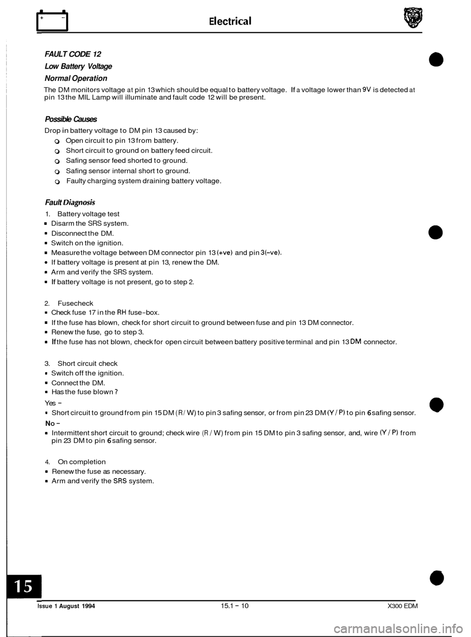
FAULT CODE 12
Low Battery Voltage
Normal Operation
The DM monitors voltage at pin 13 which should be equal to battery voltage. If a voltage lower than 9V is detected at pin 13 the MIL Lamp will illuminate and fault code 12 will be present.
Possible Causes
Drop in battery voltage to DM pin 13 caused by:
0 Open circuit to pin 13 from battery.
0 Short circuit to ground on battery feed circuit.
0 Safing sensor feed shorted to ground.
0 Safing sensor internal short to ground.
0 Faulty charging system draining battery voltage.
Fault Oiagnosis
1. Battery voltage test
Disarm the SRS system.
8 Disconnect the DM.
8 Switch on the ignition.
Measure the voltage between DM connector pin 13 (+ve) and pin 3(-ve).
If battery voltage is present at pin 13, renew the DM.
8 Arm and verify the SRS system.
8 If battery voltage is not present, go to step 2.
2.
Fusecheck
8 Check fuse 17 in the RH fuse-box.
If the fuse has blown, check for short circuit to ground between fuse and pin 13 DM connector.
8 Renew the fuse, go to step 3.
8 If the fuse has not blown, check for open circuit between battery positive terminal and pin 13 DM connector.
3. Short circuit check
* Switch off the ignition.
8 Connect the DM.
8 Has the fuse blown 1
Yes -
= Short circuit to ground from pin 15 DM (R/ W) to pin 3 safing sensor, or from pin 23 DM (Y / P) to pin 6 safing sensor.
8 Intermittent short circuit to ground; check wire (R / W) from pin 15 DM to pin 3 safing sensor, and, wire (Y/ P) from
NO -
pin 23 DM to pin 6 safing sensor.
4. On completion
8 Renew the fuse as necessary.
8 Arm and verify the SRS system.
Issue 1 August 1994 15.1 - 10 X300 EDM
Page 128 of 327
Electrical
0
FAULT CODE 24
Safing Impact Sensor Output Feed / Return Open Circuit
Normal Operation
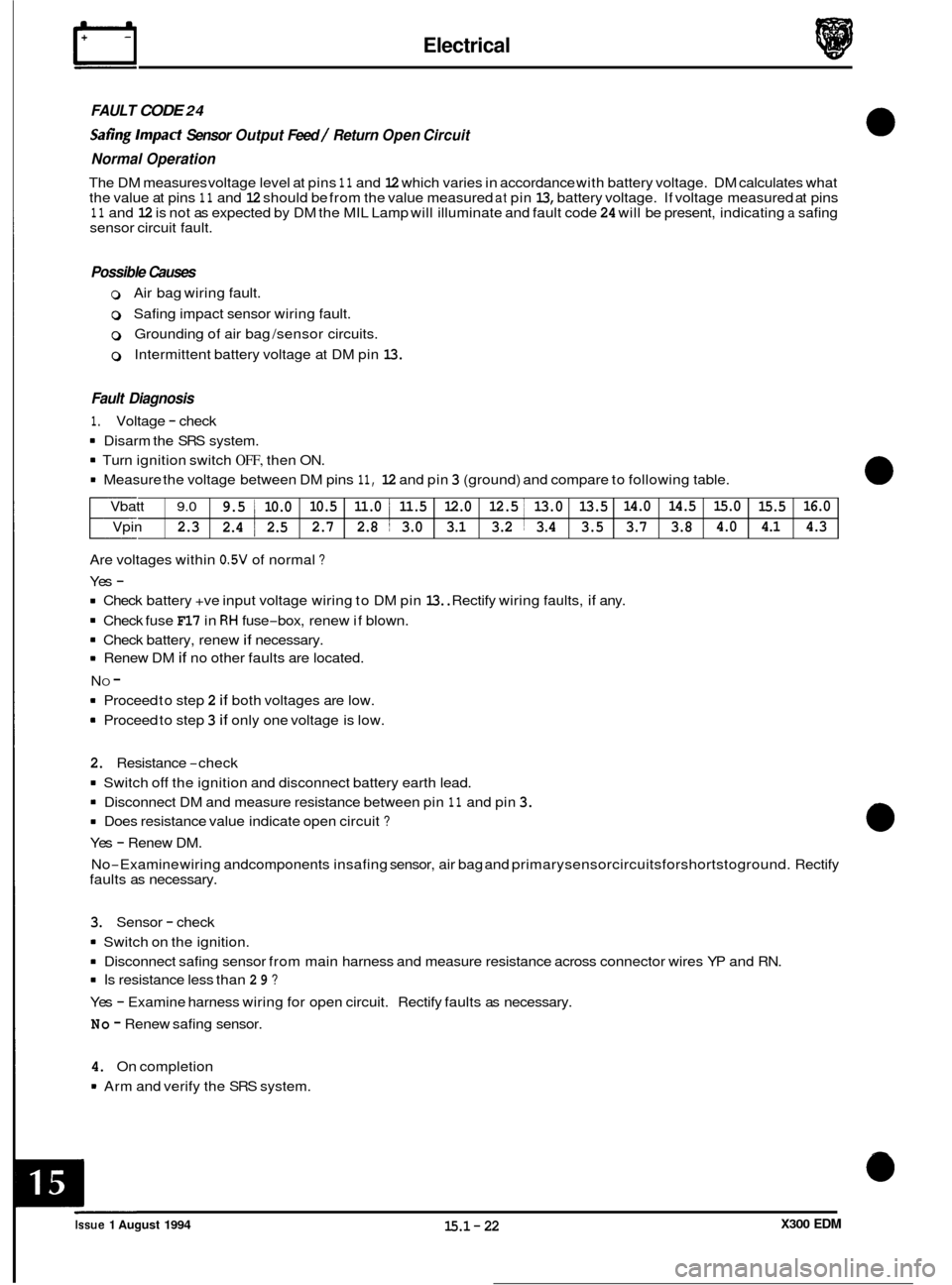
The DM measures voltage level at pins 11 and 12 which varies in accordance with battery voltage. DM calculates what
the value at pins 11 and 12 should be from the value measured at pin 13, battery voltage. If voltage measured at pins 11 and 12 is not as expected by DM the MIL Lamp will illuminate and fault code 24 will be present, indicating a safing
sensor circuit fault.
Vbatt
9.0 9.5 1 10.0 10.5
11.0 i 11.5 12.0 12.5 I 13.0 13.5 14.0
14.5 15.0
15.5
Vpin 2.3 2.4 ~ 2.5
2.7
2.8 ~ 3.0
3.1 3.2 1 3.4 3.5 3.7 3.8 4.0
4.1
Possible Causes
0 Air bag wiring fault.
0 Safing impact sensor wiring fault.
0 Grounding of air bag /sensor circuits.
0 Intermittent battery voltage at DM pin 13.
16.0 4.3
Fault Diagnosis
1. Voltage - check
8 Disarm the SRS system.
8 Turn ignition switch OFF, then ON.
8 Measure the voltage between DM pins 11, 12 and pin 3 (ground) and compare to following table.
Are voltages within
0.5V of normal ?
Yes -
8 Check battery +ve input voltage wiring to DM pin 13.. Rectify wiring faults, if any.
8 Check fuse F17 in RH fuse-box, renew if blown.
8 Check battery, renew if necessary.
8 Renew DM if no other faults are located.
8 Proceed to step 2 if both voltages are low.
8 Proceed to step 3 if only one voltage is low.
N
O -
2. Resistance -check
8 Switch off the ignition
and disconnect battery earth lead.
8 Disconnect DM and measure resistance between pin 11 and pin 3.
8 Does resistance value indicate open circuit ?
Yes - Renew DM.
No
-Examine wiring andcomponents insafing sensor, air bag and primarysensorcircuitsforshortstoground. Rectify
faults as necessary.
3. Sensor - check
8 Switch on the ignition.
8 Disconnect safing sensor from main harness and measure resistance across connector wires YP and RN.
8 Is resistance less than 29 ?
Yes - Examine harness wiring for open circuit. Rectify faults as necessary.
No - Renew safing sensor.
4. On completion
8 Arm and verify the SRS system.
X300 EDM Issue 1 August 1994 15.1 - 22
Page 182 of 327
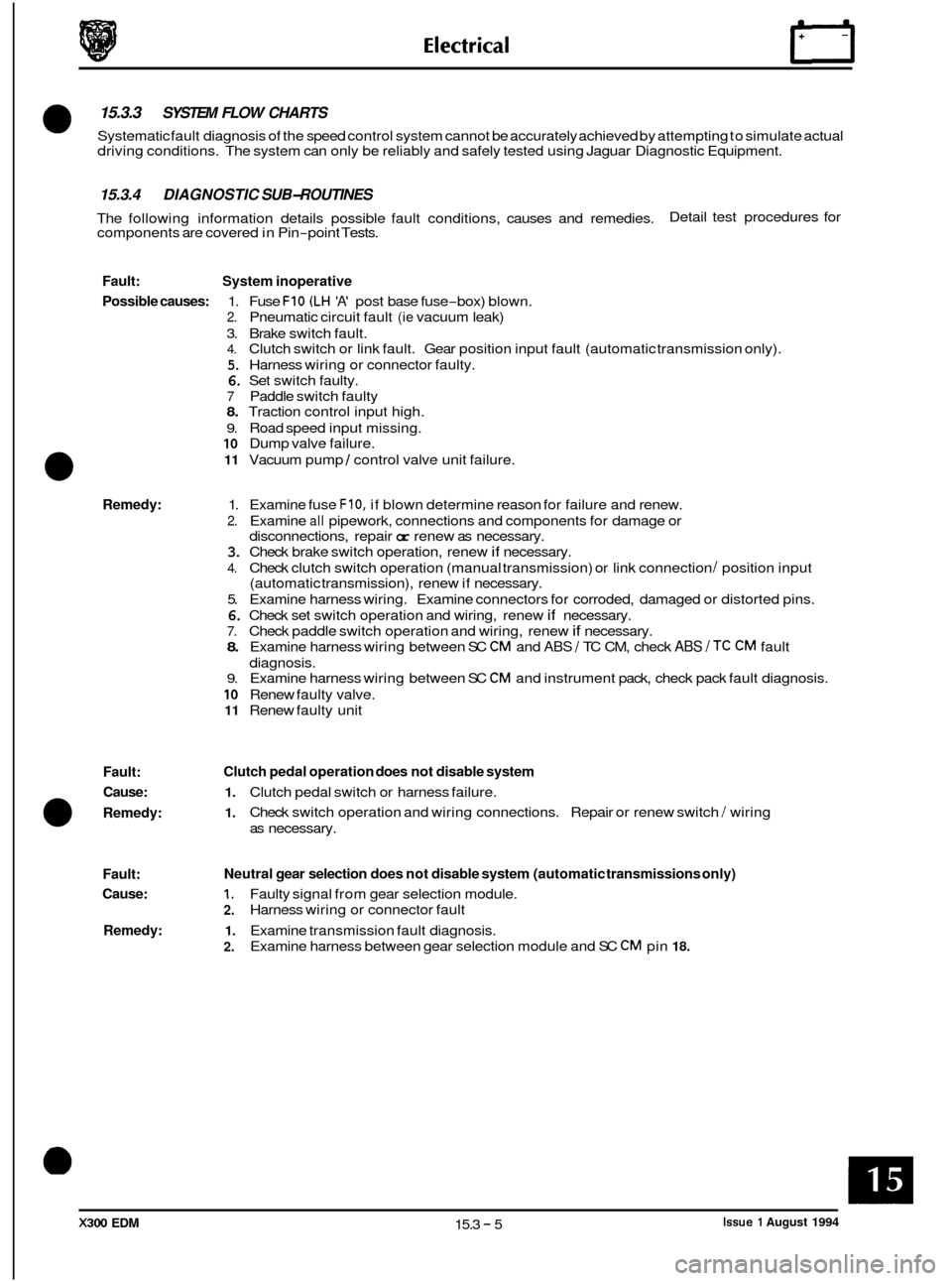
0 15.3.3 SYSTEM FLOW CHARTS
Systematic fault diagnosis of the speed control system cannot be accurately achieved by attempting to simulate actual
driving conditions. The system can only be reliably and safely tested using Jaguar Diagnostic Equipment.
15.3.4 DIAGNOSTIC SUB-ROUTINES
The following information details possible fault conditions, causes and remedies.
components are covered in Pin-point Tests. Detail test procedures
for
Fault: System inoperative
Possible causes:
1. Fuse FIO (LH 'A' post base fuse-box) blown.
2. Pneumatic circuit fault (ie vacuum leak)
3. Brake switch fault.
4. Clutch switch or link fault. Gear position input fault (automatic transmission only).
5. Harness wiring or connector faulty.
6. Set switch faulty.
7 Paddle switch faulty
8. Traction control input high.
9. Road speed input missing.
10 Dump valve failure.
11 Vacuum pump 1 control valve unit failure.
Remedy: 1. Examine fuse F10, if blown determine reason for failure and renew.
2. Examine all pipework, connections and components for damage or
disconnections, repair
or renew as necessary.
3. Check brake switch operation, renew if necessary.
4. Check clutch switch operation (manual transmission) or link connection I position input
(automatic transmission), renew if necessary.
5. Examine harness wiring. Examine connectors for corroded, damaged or distorted pins.
6. Check set switch operation and wiring, renew if necessary.
7. Check paddle switch operation and wiring, renew if necessary.
8. Examine harness wiring between SC CM and ABS / TC CM, check ABS /TC CM fault
diagnosis.
9. Examine harness wiring between SC CM and instrument pack, check pack fault diagnosis.
10 Renew faulty valve.
11 Renew faulty unit
0
Fault:
Cause:
1. Clutch pedal switch or harness failure.
Clutch pedal operation does not disable system
1. Remedy: Check switch operation and wiring connections. Repair or renew switch / wiring
as necessary.
Fault:
Cause:
1, Faulty signal from gear selection module.
Remedy: 1. Examine transmission fault diagnosis.
Neutral gear selection does not disable system (automatic transmissions only)
2.
2.
Harness wiring or connector fault
Examine harness between gear selection module and SC
CM pin 18.
X300 EDM 15.3 - 5 Issue 1 August 1994
Page 184 of 327
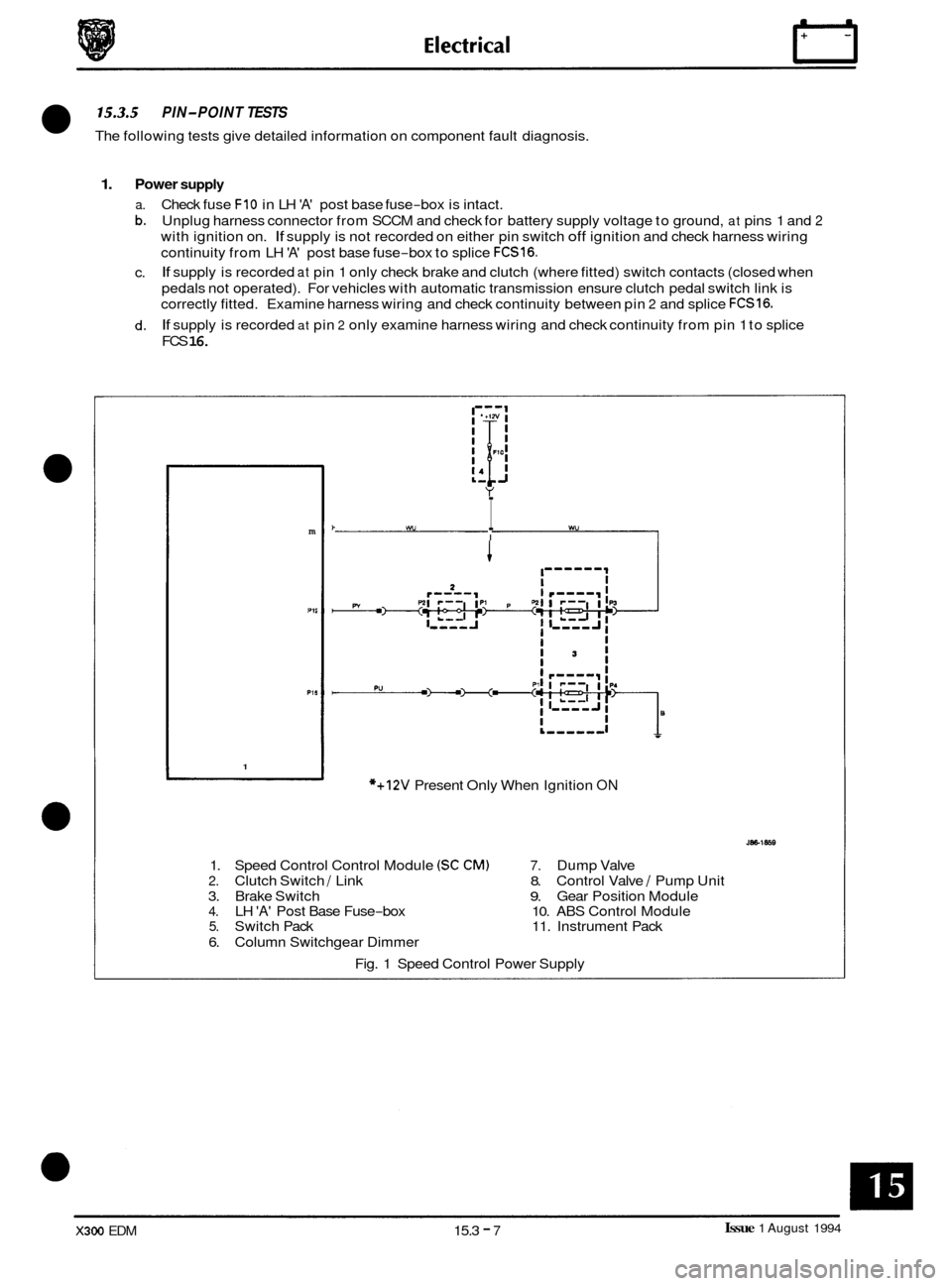
15.3.5 PIN-POINT TESTS
The following tests give detailed information on component fault diagnosis.
1. Power supply
a. Check fuse FIO in LH 'A' post base fuse-box is intact.
b. Unplug harness connector from SCCM and check for battery supply voltage to ground, at pins 1 and 2
with ignition on. If supply is not recorded on either pin switch off ignition and check harness wiring
continuity from LH
'A' post base fuse-box to splice FCS16.
If supply is recorded at pin 1 only check brake and clutch (where fitted) switch contacts (closed when
pedals not operated). For vehicles with automatic transmission ensure clutch pedal switch link is
correctly fitted. Examine harness wiring and check continuity between pin
2 and splice FCS16.
If supply is recorded at pin 2 only examine harness wiring and check continuity from pin 1 to splice
FCS
16.
c.
d.
m
P1I
1
k wv I wu I
I-------
*+12V Present Only When Ignition ON
1. Speed Control Control Module (SC CM) 7. Dump Valve
2. Clutch Switch / Link 8. Control Valve / Pump Unit
3. Brake Switch
9. Gear Position Module 4. LH 'A' Post Base Fuse-box 10. ABS Control Module 5. Switch Pack 11. Instrument Pack
6. Column Switchgear Dimmer
Fig. 1 Speed Control Power Supply
Issue 1 August 1994 X300 EDM 15.3 - 7
Page 185 of 327
n Electrical
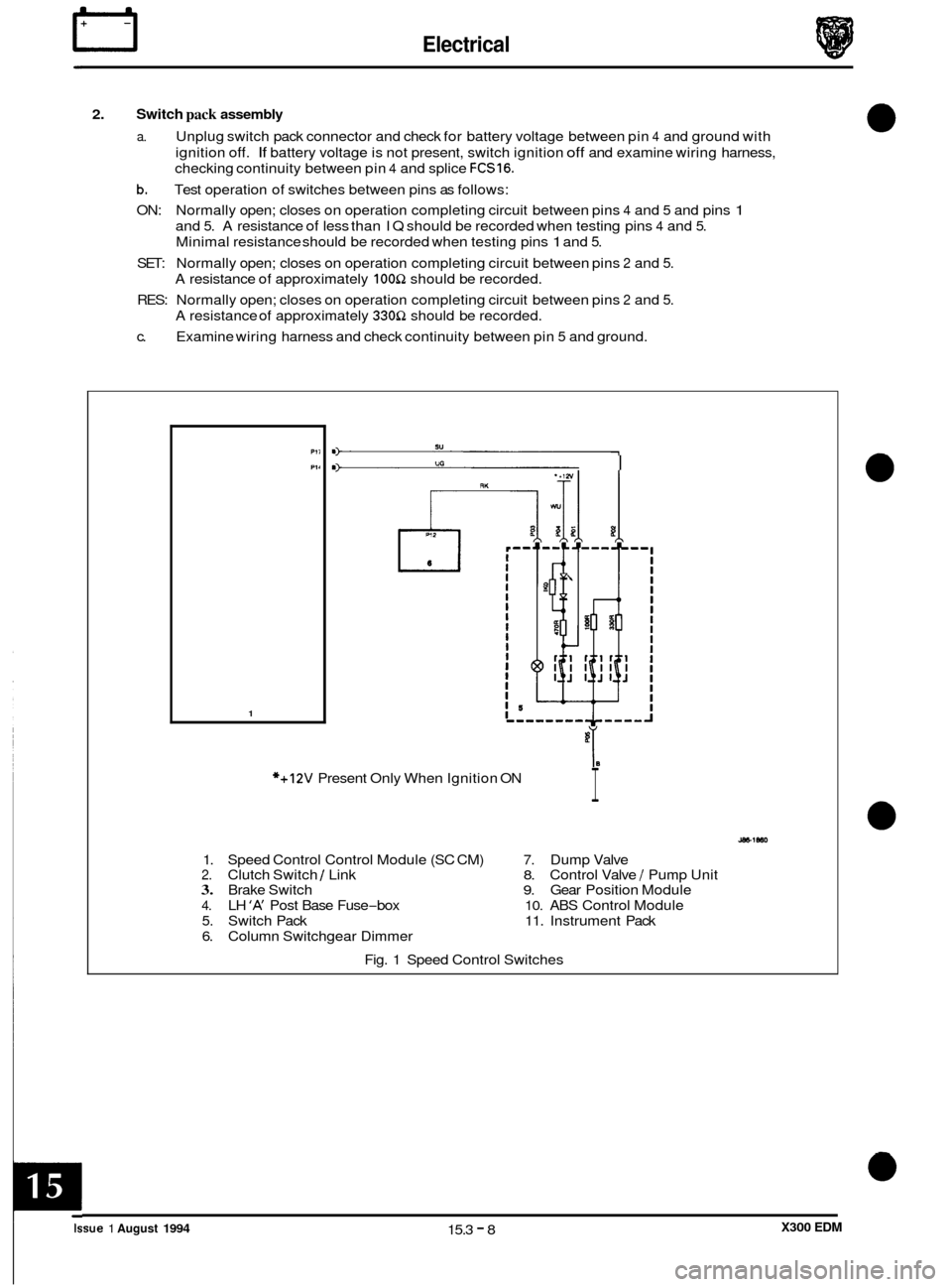
2. Switch pack assembly
a. Unplug switch pack connector and check for battery voltage between pin 4 and ground with
ignition
off. If battery voltage is not present, switch ignition off and examine wiring harness,
checking continuity between pin
4 and splice FCS16.
b. Test operation of switches between pins as follows:
ON: Normally open; closes on operation completing circuit between pins
4 and 5 and pins 1
and 5. A resistance of less than IQ should be recorded when testing pins 4 and 5.
Minimal resistance should be recorded when testing pins 1 and 5.
SET: Normally open; closes on operation completing circuit between pins 2 and 5.
A resistance of approximately 100Q should be recorded.
RES: Normally open; closes on operation completing circuit between pins
2 and 5.
A resistance of approximately 330Q should be recorded.
c. Examine wiring harness and check continuity between pin
5 and ground.
Ptl
PI1
1
m) su
I U0
I
*+12V Present Only When Ignition ON
1. Speed Control Control Module (SC CM)
7. Dump Valve 2. Clutch Switch I Link 8. Control Valve / Pump Unit 3. Brake Switch 9. Gear Position Module
4. LH ‘A’ Post Base Fuse-box 10. ABS Control Module
5. Switch Pack 11. Instrument Pack
6. Column Switchgear Dimmer
Fig. 1 Speed Control Switches
0
0
0
0
Issue 1 August 1994 15.3 - 8 X300 EDM
Page 186 of 327
E I ect r ica I n
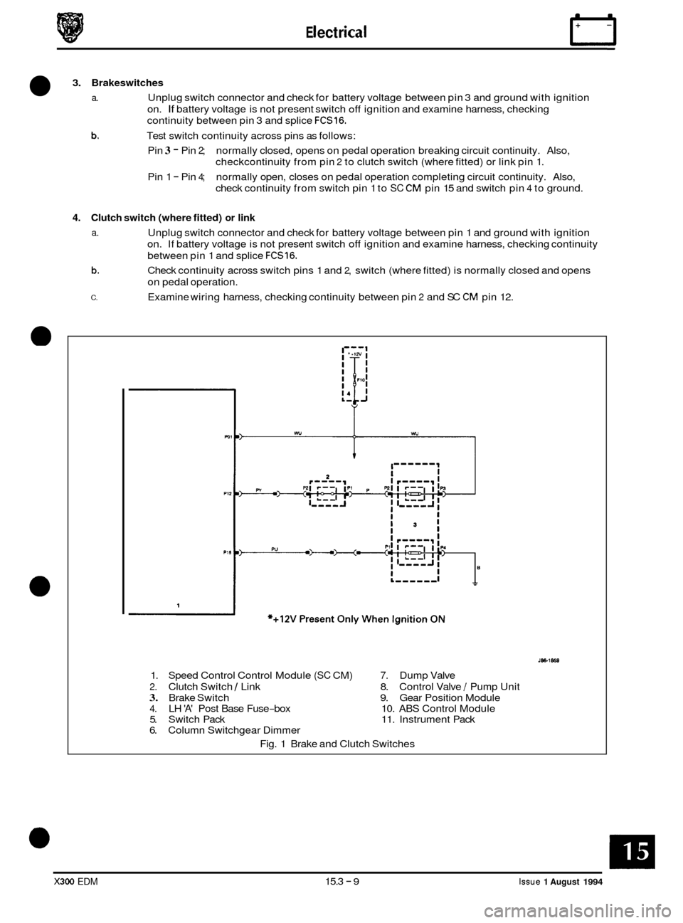
3. Brakeswitches
a. Unplug switch connector and check for battery voltage between pin 3 and ground with ignition
b.
on. If battery voltage is not present switch off ignition and examine harness, checking
continuity between pin 3 and splice
FCS16.
Test switch continuity across pins as follows:
Pin
3 - Pin 2; normally closed, opens on pedal operation breaking circuit continuity. Also,
checkcontinuity from pin
2 to clutch switch (where fitted) or link pin 1.
Pin 1
- Pin 4; normally open, closes on pedal operation completing circuit continuity. Also,
check continuity from switch pin 1 to
SC CM pin 15 and switch pin 4 to ground.
4. Clutch switch (where fitted) or link
a. Unplug switch connector and check for battery voltage between pin 1 and ground with ignition
on. If battery voltage is not present switch
off ignition and examine harness, checking continuity
between pin 1 and splice
FCS16.
Check continuity across switch pins 1 and 2, switch (where fitted) is normally closed and opens
on pedal operation.
Examine wiring harness, checking continuity between pin
2 and SC CM pin 12.
b.
C.
1
.---I
1. Speed Control Control Module (SC CM) 7. Dump Valve
2. Clutch Switch 1 Link 8. Control Valve / Pump Unit
3. Brake Switch 9. Gear Position Module 4. LH 'A' Post Base Fuse-box 10. ABS Control Module
5. Switch Pack 11. Instrument Pack
6. Column Switchgear Dimmer
Fig. 1 Brake and Clutch Switches
X300 EDM 15.3 - 9 Issue 1 August 1994
Page 187 of 327
rl E I ect r ica I
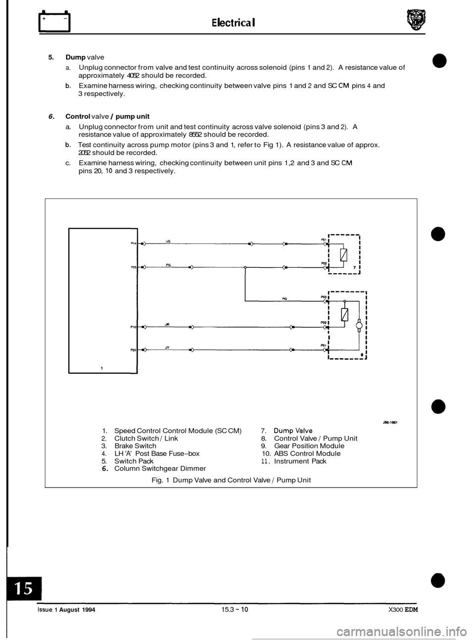
5. Dump valve
a.
b.
Unplug connector from valve and test continuity across solenoid (pins 1 and 2). A resistance value of
approximately 4052 should be recorded.
Examine harness wiring, checking continuity between valve pins 1 and
2 and SC CM pins 4 and
3 respectively.
6. Control valve / pump unit
a. Unplug connector from unit and test continuity across valve solenoid (pins 3 and 2). A
resistance value of approximately 8552 should be recorded.
b. Test continuity across pump motor (pins 3 and 1, refer to Fig 1). A resistance value of approx.
2052 should be recorded.
c. Examine harness wiring, checking continuity between unit pins 1,2 and 3 and SC
CM
pins 20, 10 and 3 respectively.
I Ii
1
1. Speed Control Control Module (SC CM) 7. Dumpvalve
2. Clutch Switch / Link 8. Control Valve / Pump Unit
3. Brake Switch 9. Gear Position Module
4. LH 'A' Post Base Fuse-box 10. ABS Control Module
5. Switch Pack
11. Instrument Pack 6. Column Switchgear Dimmer
Fig. 1 Dump Valve and Control Valve
/ Pump Unit
0
0
0
0
Issue 1 August 1994 15.3 - 10 X300 EDM
Page 188 of 327
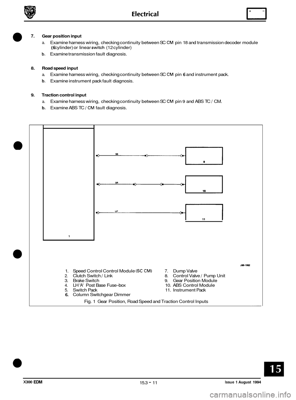
7. Gear position input
a. Examine harness wiring, checking continuity between SC CM pin 18 and transmission decoder module
(6 cylinder) or linear switch (12 cylinder)
b. Examine transmission fault diagnosis.
8. Road speed input
a. Examine harness wiring, checking continuity between SC CM pin 6 and instrument pack.
b. Examine instrument pack fault diagnosis.
9. Traction control input
a.
b.
Examine harness wiring, checking continuity between SC CM pin 9 and ABS TC J CM.
Examine ABS TC
J CM fault diagnosis.
1
1. Speed Control Control Module (SC CM) 7. Dump Valve
2. Clutch Switch J Link 8. Control Valve / Pump Unit
3. Brake Switch
9. Gear Position Module 4. LH 'A' Post Base Fuse-box 10. ABS Control Module
5. Switch Pack 11. Instrument Pack 6. Column Switchgear Dimmer
Fig. 1 Gear Position, Road Speed and Traction Control Inputs
Issue 1 August 1994 15.3 - 11 X300 EDM
Page 214 of 327
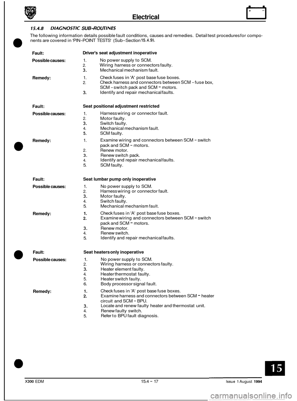
Electrical rl
15.4.8 DlAG NOSTIC SUB-ROU T1 NES
0
The following information details possible fault conditions, causes and remedies. Detail test procedures for compo-
nents are covered in 'PIN-POINT TESTS' (Sub-Section 15.4.9).
Fault:
Possible causes:
Remedy:
Fault: Possible causes:
Remedy:
0
Fault:
Possible causes:
Remedy:
Fault:
Possible causes:
Remedy: Driver's
seat adjustment inoperative
1.
2.
3. Mechanical mechanism fault.
1.
2.
3.
No power supply to SCM.
Wiring harness or connectors faulty.
Check fuses
in 'A' post base fuse boxes.
Check harness and connectors between
SCM -fuse box,
SCM
-switch pack and SCM - motors.
Identify and repair mechanical faults.
Seat positional adjustment restricted
1.
2. Motor faulty.
3. Switch faulty.
4. Mechanical mechanism fault.
5. SCM faulty.
1.
2. Renew motor.
3. Renew switch pack.
4.
5. SCM faulty.
Harness
wiring or connector fault.
Examine wiring and connectors between SCM
- switch
pack and SCM
- motors.
Identify and repair mechanical faults.
Seat lumbar pump only inoperative
1.
2.
3. Motor faulty.
4. Switch faulty.
5. Mechanical mechanism
fault.
1.
2.
3. Renew motor.
4. Renew switch.
5. No
power supply to SCM.
Harness wiring or connector fault.
Check fuses in
'A' post base fuse boxes.
Examine wiring and connectors between SCM
- switch
pack and SCM
- motors.
Identify and repair mechanical faults.
Seat heaters only inoperative
1.
2.
3. Heater element faulty.
4. Heater thermostat faulty.
5. Heater switch faulty.
6. Body processor signal fault.
1.
2.
3.
4. Renew faulty switch.
5.
No power supply to SCM.
Wiring harness or connectors faulty.
Check fuses in
'A' post base fuse boxes.
Examine harness and connectors between SCM
- heater
circuit and SCM
- BPU.
Locate and renew faulty heater and thermostat unit.
Refer to BPU fault diagnosis.
X300 EDM 15.4 - 17 Issue 1 August 1994
Page 215 of 327
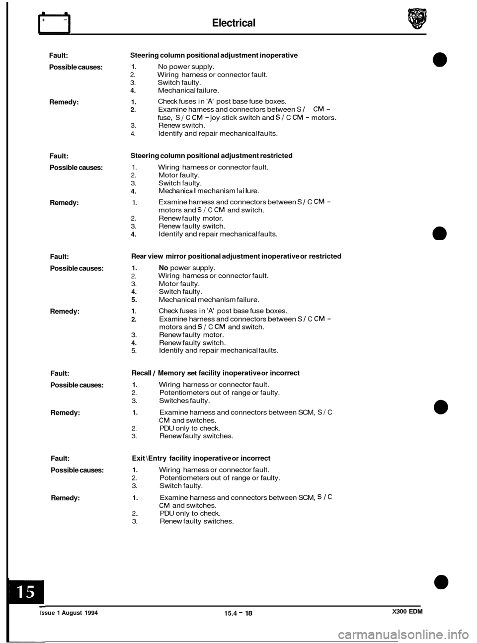
Electrical IT
Fault:
Possible causes:
Remedy:
Fault: Possible causes:
Remedy:
Fault:
Possible causes:
Remedy:
Fault:
Possible causes:
Remedy:
Fault:
Possible causes:
Remedy: Steering
column positional adjustment inoperative
1. No power supply.
2. Wiring harness or connector fault.
3. Switch faulty.
4. Mechanical failure.
1. 2. Examine harness and connectors between S 1 CM -
3. Renew switch.
4.
Check fuses in 'A' post base fuse boxes.
fuse,
S I C CM - joy-stick switch and SI C CM - motors.
Identify and repair mechanical faults.
Steering column positional adjustment restricted
1. Wiring harness or connector fault.
2. Motor faulty.
3. Switch faulty.
4.
1.
2. Renew faulty motor.
3. Renew faulty switch.
4.
M echa n ica I mechanism fa i I u re.
Examine harness and connectors between
S 1 C CM -
motors and SI C CM and switch.
Identify and repair mechanical faults.
Rear view mirror positional adjustment inoperative or restricted
1. No power supply.
2.
3. Motor faulty.
4. Switch faulty.
5. Mechanical mechanism failure.
1.
2.
3. Renew faulty motor.
4. Renew faulty switch.
5.
Wiring harness or connector fault.
Check fuses in
'A' post base fuse boxes.
Examine harness and connectors between
S 1 C CM -
motors and SI C CM and switch.
Identify and repair mechanical faults.
Recall / Memory set facility inoperative or incorrect
1. Wiring harness or connector fault.
2. Potentiometers out of range or faulty.
3. Switches faulty.
1. Examine harness and connectors between SCM, S I C
CM and switches.
2. PDU only to check.
3. Renew faulty switches.
Exit \Entry facility inoperative or incorrect
1. Wiring harness or connector fault.
2. Potentiometers out of range or faulty.
3. Switch faulty.
1. Examine harness and connectors between SCM, S 1 C
CM and switches.
2.. PDU only to check.
3. Renew faulty switches. ~
Issue 1 August 1994 15.4 - 18 X300 EDM