fuse box JAGUAR XJ6 1994 2.G Electrical Diagnostic Manual
[x] Cancel search | Manufacturer: JAGUAR, Model Year: 1994, Model line: XJ6, Model: JAGUAR XJ6 1994 2.GPages: 327, PDF Size: 13.73 MB
Page 216 of 327
15.4.9 PIN-POINT TESTS
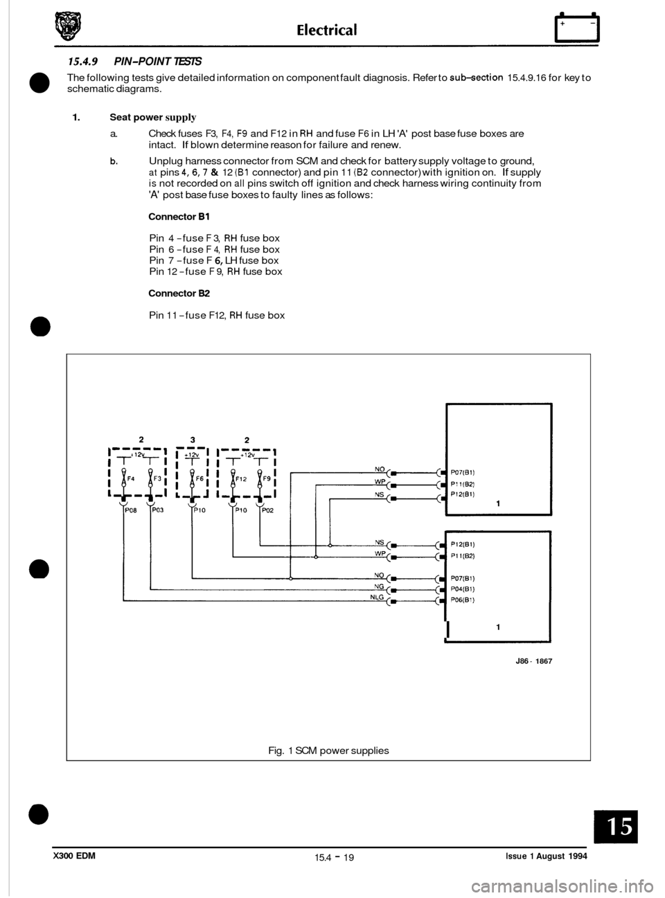
The following tests give detailed information on component fault diagnosis. Refer to sub-section 15.4.9.16 for key to
schematic diagrams.
1. Seat power supply
a.
b.
Check fuses F3, F4, F9 and F12 in RH and fuse F6 in LH 'A' post base fuse boxes are
intact.
If blown determine reason for failure and renew.
Unplug harness connector from SCM and check for battery supply voltage to ground,
at pins 4,6,7 & 12 (B1 connector) and pin 11 (82 connector) with ignition on. If supply
is not recorded on all pins switch off ignition and check harness wiring continuity from
'A' post base fuse boxes to faulty lines as follows:
Connector B1
Pin 4 -fuse F 3, RH fuse box
Pin
6 -fuse F 4, RH fuse box
Pin
7 -fuse F 6, LH fuse box
Pin
12 -fuse F 9, RH fuse box
Connector 82
Pin 11 -fuse F12, RH fuse box
1 I
J86 - 1867
Fig. 1 SCM power supplies
Issue 1 August 1994 15.4 - 19 X300 EDM
Page 217 of 327
n E I ectr ical
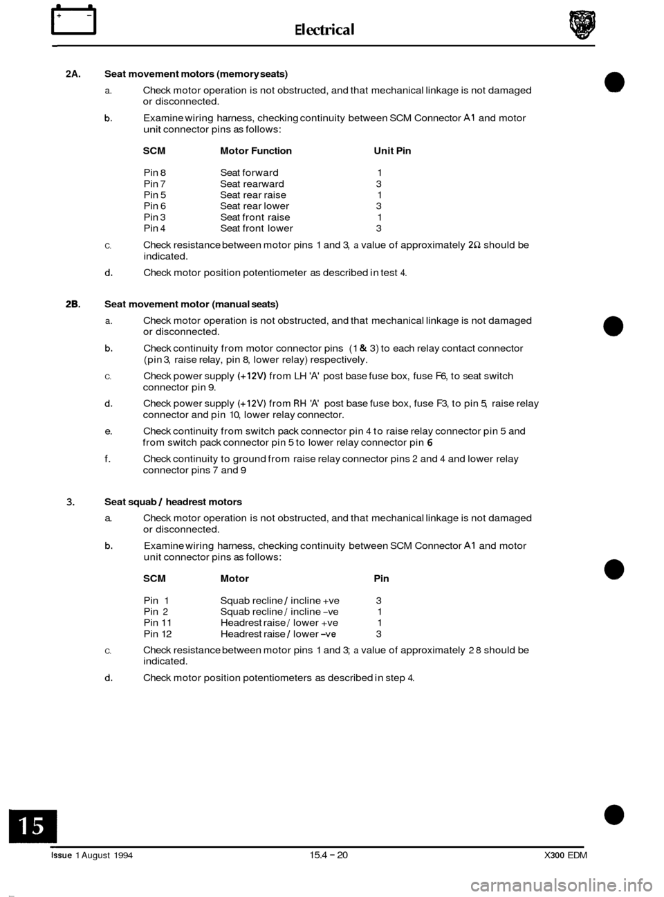
2A. Seat movement motors (memory seats)
a.
b.
Check motor operation is not obstructed, and that mechanical linkage is not damaged
or disconnected.
Examine wiring harness, checking continuity between SCM Connector
A1 and motor
unit connector pins as follows:
SCM Motor Function Unit Pin
Pin 8 Seat forward 1
Pin
7 Seat rearward 3
Pin 5 Seat rear raise 1
Pin
6 Seat rear lower 3
Pin 3 Seat front raise 1
Pin
4 Seat front lower 3
Check resistance between motor pins 1 and 3, a value of approximately 2S2 should be
indicated.
Check motor position potentiometer as described in test
4.
C.
d.
28. Seat movement motor (manual seats)
a.
b.
C.
d.
Check motor operation is not obstructed, and that mechanical linkage is not damaged
or disconnected.
Check continuity from motor connector pins (1
& 3) to each relay contact connector
(pin
3, raise relay, pin 8, lower relay) respectively.
Check power supply
(+12V) from LH 'A' post base fuse box, fuse F6, to seat switch
connector pin
9.
Check power supply (+12V) from RH 'A' post base fuse box, fuse F3, to pin 5, raise relay
connector and pin 10, lower relay connector.
Check continuity from switch pack connector pin
4 to raise relay connector pin 5 and
from switch pack connector pin 5 to lower relay connector pin
6
Check continuity to ground from raise relay connector pins 2 and 4 and lower relay
connector pins
7 and 9
e.
f.
3. Seat squab 1 headrest motors
a.
b.
Check motor operation is not obstructed, and that mechanical linkage is not damaged
or disconnected.
Examine wiring harness, checking continuity between SCM Connector
A1 and motor
unit connector pins as follows:
SCM Motor Pin
Pin 1 Squab recline 1 incline +ve 3
Pin 2 Squab recline 1 incline -ve 1
Pin 11 Headrest raise
1 lower +ve 1
Pin 12 Headrest raise
1 lower -ve 3
Check resistance between motor pins 1 and 3; a value of approximately 28 should be
indicated.
Check motor position potentiometers as described in step
4.
C.
d.
Issue 1 August 1994 15.4 - 20 X300 EDM
Page 222 of 327
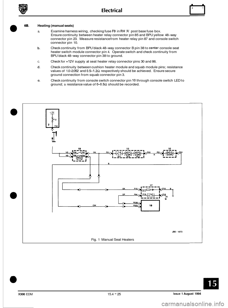
68. Heating (manual seats)
0 a. Examine harness wiring, checking fuse F9 in RH 'A' post base fuse box.
Ensure continuity between heater relay connector pin 85 and BPU yellow 48
-way
connector pin 23. Measure resistance from heater relay pin 87 and console switch
connector pin 10.
Check continuity from BPU black 48
-way connector B pin 38 to center console seat
heater switch module connector pin
4. Operate switch and check continuity from
BPU black 48
-way connector pin 38 to ground.
Check for
+12V supply at seat heater relay connector pins 30 and 86.
Check continuity between cushion heater module and squab module pins; resistance
values
of 1.0-2.052 and 0.5-1.252 respectively should be achieved. Ensure secure
ground connection from squab connector pin 3.
Check continuity from console switch connector pin
10 through console switch LED to
ground;
a resistance value of 0-0.5Q should be recorded.
b.
C.
d.
e.
I' T
I 19 15 16
17 OK
J86 - 1873
Fig. 1 Manual Seat Heaters
Issue 1 August 1994 X300 EDM 15.4 - 25
Page 226 of 327
E I ect r ica I
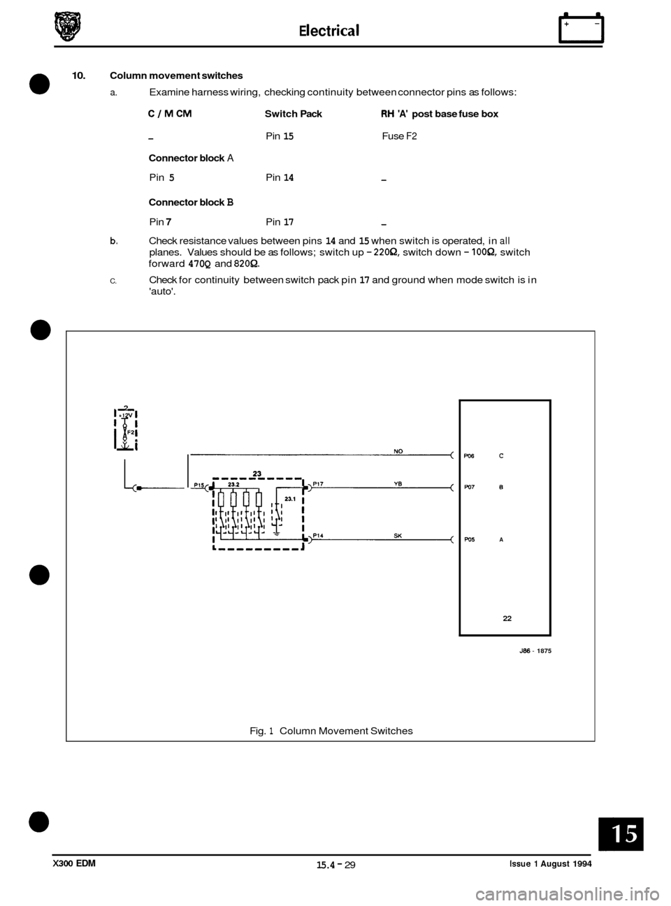
10. Column movement switches
0 a. Examine harness wiring, checking continuity between connector pins as follows:
CIMCM Switch Pack RH 'A' post base fuse box
- Pin 15 Fuse F2
Connector block A
Pin 5 Pin 14 -
Connector block B
Pin 7 Pin 17 -
Check resistance values between pins 14 and 15 when switch is operated, in all
planes. Values should be as follows; switch up - 220Q, switch down - IOOQ, switch
forward
470Q and 8208.
Check for continuity between switch pack pin 17 and ground when mode switch is in
'auto'.
b.
C.
2
1
'5i 11 v
L-
L-,,,,,,,,J
Fig. 1 Column Movement Switches
PO6 C
PO7 B
w5 A
22
J86 - 1875
Issue 1 August 1994 15.4 - 29 X300 EDM
Page 232 of 327
E I ect r ica I rl
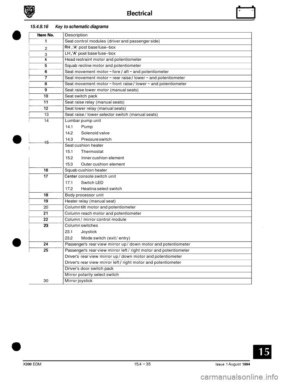
15.4.9.16 Key to schematic diagrams
I 2
I 3
i 7
, I 13
14
a1 15
j
20
p
23
30
Description
Seat control modules (driver and passenger side)
RH ,'A' post base fuse-box
LH
,'A' post base fuse-box
Head restraint motor and potentiometer
Squab recline motor and potentiometer
Seat movement motor
- fore 1 aft - and potentiometer
Seat movement motor
- rear raise 1 lower - and potentiometer
Seat movement motor
- front raise 1 lower - and potentiometer
Seat raise lower motor (manual seats)
Seat switch pack
Seat raise relay (manual seats)
Seat lower relay (manual seats)
Seat raise
/ lower selector switch (manual seats)
Lumbar pump unit
14.1 Pump
14.2 Solenoid valve
14.3 Pressure switch
Seat cushion heater
15.1 Thermostat
15.2 Inner cushion element
15.3 Outer cushion element
Squab cushion heater
Center console switch unit
17.1 Switch LED
17.2 Heatina select switch
Body processor unit
Heater relay (manual seat)
Column
tilt motor and potentiometer
Column reach motor and potentiometer
Column
I mirror control module
Column switches
23.1 Joystick
23.2 Passenger's rear view mirror up
I down motor and potentiometer
Passenger's rear view mirror left
I right motor and potentiometer
Mode switch (exit
I entry)
Driver's rear view mirror up
I down motor and potentiometer
Driver's rear view mirror left
1 right motor and potentiometer
Driver's door switch pack
Mirror polarity select switch
Mirror joystick
X300 EDM 15.4 - 35 Issue 1 August 1994
Page 233 of 327
E I ect r ica I
15.4.10 ELECTROCHROMATIC REAR VIEW MIRROR
15.4.10.1 Description
The function of the electrochromatic rearview mirror is to vary the reflectivity of the mirror glass. The mirror automati- cally varies its reflectivity to accommodate changes in traffic and light conditions to provide the driver with optimized
forward and rear vision.
The mirror contains an ambient sensor (forward facing) and
a glare sensor (rearward facing). Sensitivity control is
adjustable and at the lowest end of sensitivity control is system off. A reverse over-ride facility is incorporated; when
reverse gear is selected, the mirror operates in a high reflective state.
15.4.10.2 Test Procedure
The ambient and glare sensors and associated circuitry, the sensitivity control and reverse over-ride circuitry are all
contained within the mirror unit. Therefore only the inputs to the mirror unit can be interrogated, and if correct, the
mirror unit is defaulted.
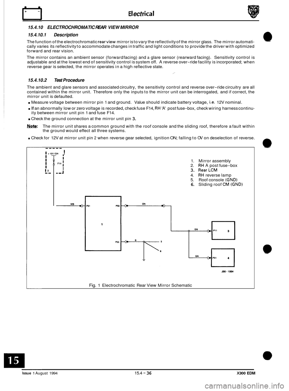
. Measure voltage between mirror pin 1 and ground. Value should indicate battery voltage, i.e. 12V nominal.
. If an abnormally low or zero voltage is recorded, check fuse F14, RH 'A' post fuse-box, check wiring harness continu-
. Check the ground connection at the mirror unit pin 3.
Note: The mirror unit shares a common ground with the roof console and the sliding roof, therefore a fault within
the ground would effect all three systems.
. Check for 12V at mirror unit pin 2 when reverse gear selected, ignition ON; falling to OV on deselection of reverse.
/
ity between mirror unit pin 1 and fuse F14.
----- I +12VIGN ! I I I
I
L',
I I
I ,,J
F14 1. Mirror assembly
2. RH A post fuse-box
3. RearLCM
4. RH reverse lamp
5. Roof console (GND) 6. Sliding roof CM (GND)
J86-1864
Fig. 1 Electrochromatic Rear View Mirror Schematic
Issue 1 August 1994 15.4 - 36 X300 EDM