15.4.9 PIN-POINT TESTS
The following tests give detailed information on component fault diagnosis. Refer to sub-section 15.4.9.16 for key to
schematic diagrams.
1. Seat power supply
a.
b.
Check fuses F3, F4, F9 and F12 in RH and fuse F6 in LH 'A' post base fuse boxes are
intact.
If blown determine reason for failure and renew.
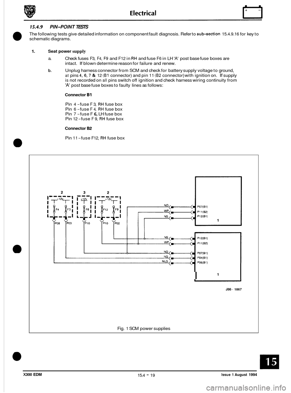
Unplug harness connector from SCM and check for battery supply voltage to ground,
at pins 4,6,7 & 12 (B1 connector) and pin 11 (82 connector) with ignition on. If supply
is not recorded on all pins switch off ignition and check harness wiring continuity from
'A' post base fuse boxes to faulty lines as follows:
Connector B1
Pin 4 -fuse F 3, RH fuse box
Pin
6 -fuse F 4, RH fuse box
Pin
7 -fuse F 6, LH fuse box
Pin
12 -fuse F 9, RH fuse box
Connector 82
Pin 11 -fuse F12, RH fuse box
1 I
J86 - 1867
Fig. 1 SCM power supplies
Issue 1 August 1994 15.4 - 19 X300 EDM
E I ect r ica I rl
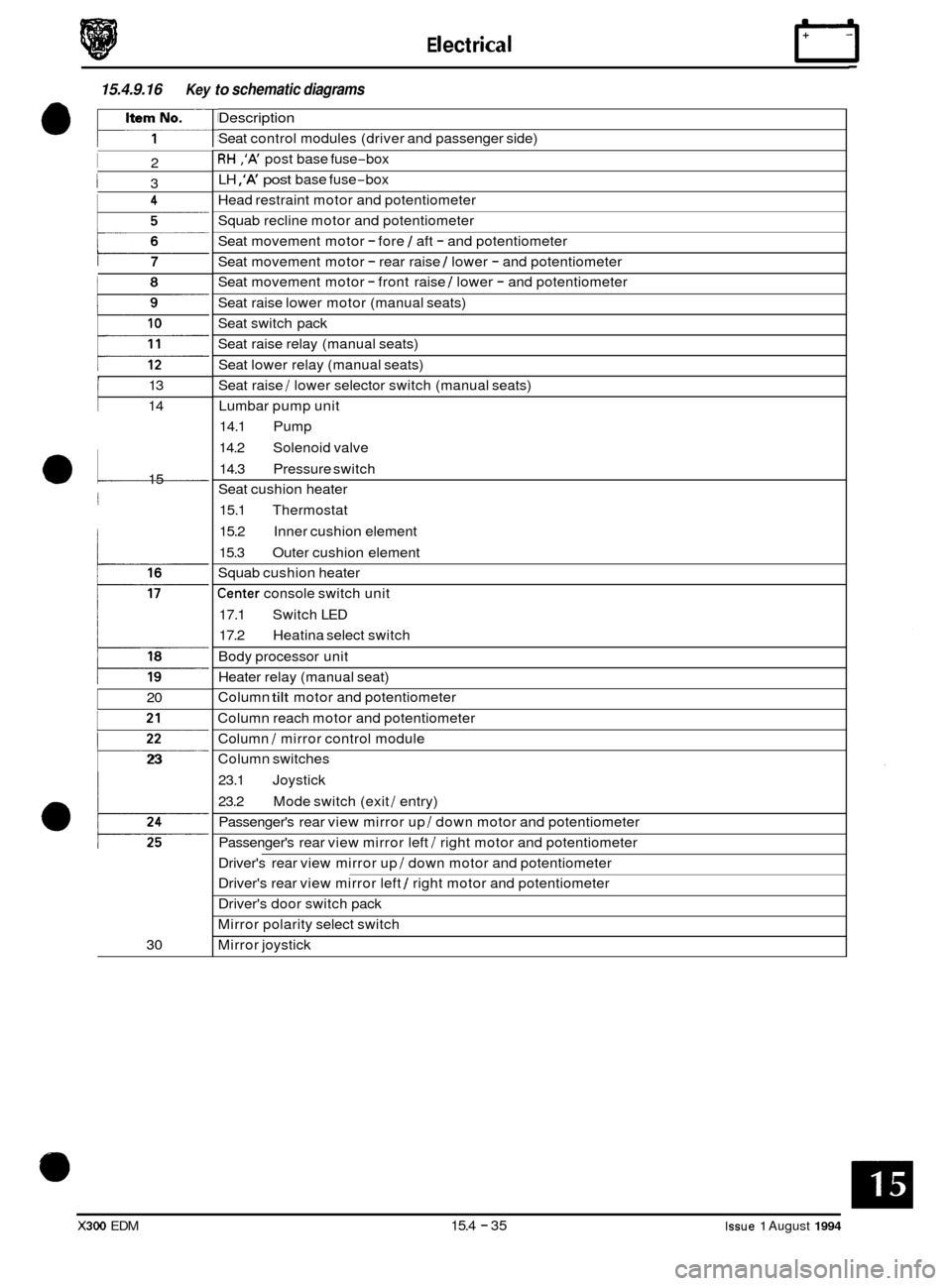
15.4.9.16 Key to schematic diagrams
I 2
I 3
i 7
, I 13
14
a1 15
j
20
p
23
30
Description
Seat control modules (driver and passenger side)
RH ,'A' post base fuse-box
LH
,'A' post base fuse-box
Head restraint motor and potentiometer
Squab recline motor and potentiometer
Seat movement motor
- fore 1 aft - and potentiometer
Seat movement motor
- rear raise 1 lower - and potentiometer
Seat movement motor
- front raise 1 lower - and potentiometer
Seat raise lower motor (manual seats)
Seat switch pack
Seat raise relay (manual seats)
Seat lower relay (manual seats)
Seat raise
/ lower selector switch (manual seats)
Lumbar pump unit
14.1 Pump
14.2 Solenoid valve
14.3 Pressure switch
Seat cushion heater
15.1 Thermostat
15.2 Inner cushion element
15.3 Outer cushion element
Squab cushion heater
Center console switch unit
17.1 Switch LED
17.2 Heatina select switch
Body processor unit
Heater relay (manual seat)
Column
tilt motor and potentiometer
Column reach motor and potentiometer
Column
I mirror control module
Column switches
23.1 Joystick
23.2 Passenger's rear view mirror up
I down motor and potentiometer
Passenger's rear view mirror left
I right motor and potentiometer
Mode switch (exit
I entry)
Driver's rear view mirror up
I down motor and potentiometer
Driver's rear view mirror left
1 right motor and potentiometer
Driver's door switch pack
Mirror polarity select switch
Mirror joystick
X300 EDM 15.4 - 35 Issue 1 August 1994

