torque JAGUAR XJ6 1994 2.G Electrical Diagnostic Manual
[x] Cancel search | Manufacturer: JAGUAR, Model Year: 1994, Model line: XJ6, Model: JAGUAR XJ6 1994 2.GPages: 327, PDF Size: 13.73 MB
Page 41 of 327
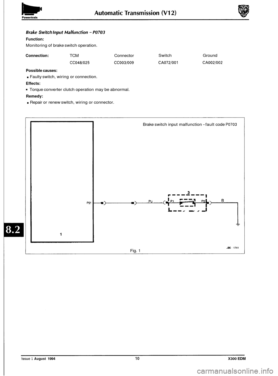
Srake Switch lnpiit Malfiincfion - PO703
Function:
Monitoring of brake switch operation.
Connection: TCM Connector
CC048/025 CC003/009
Possible causes:
. Faulty switch, wiring or connection.
Effects:
Torque converter clutch operation may be abnormal.
Remedy:
. Repair or renew switch, wiring or connector. Switch
CA072/001
Ground
CA002/002
P2!
1
Brake
switch input malfunction -fault code PO703
I -I I I I I I ,I
J86 - 1741 Fig. 1
Issue 1 August 1994 10 X300 EDM
Page 44 of 327
Automatic Transmission (V12) Powertrain
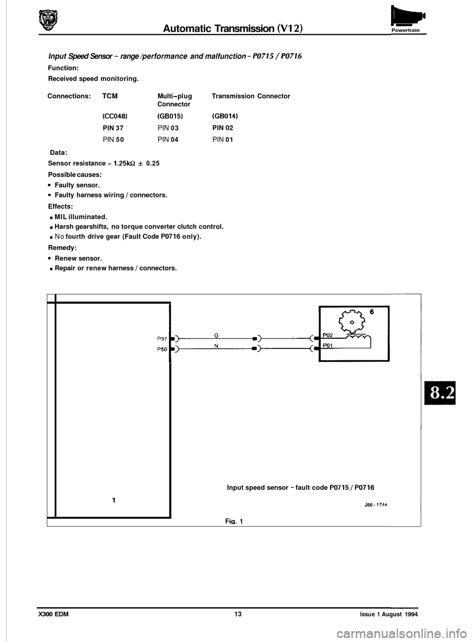
Input Speed Sensor - range /performance and malfunction - PO715 / PO716
Function:
Received speed monitoring.
Transmission Connector
(GB014)
PIN 02
PIN 01
Connections: TCM Multi-pl ug
Connector
(CC048) (GB015)
PIN 37 PIN 03
PIN 50 PIN 04
Data:
Sensor resistance = 1.25kQ f 0.25
Possible causes:
9 Faulty sensor.
9 Faulty harness wiring 1 connectors.
Effects:
. MIL illuminated.
. Harsh gearshifts, no torque converter clutch control.
. No fourth drive gear (Fault Code PO716 only).
Remedy:
. Repair or renew harness 1 connectors.
Renew sensor.
0
0
1
Input speed sensor - fault code PO715 / PO716
J86 - 1714
Fig. 1
X300 EDM 13 Issue 1 August 1994
Page 48 of 327
Powertrain Automatic Transmission (V12)
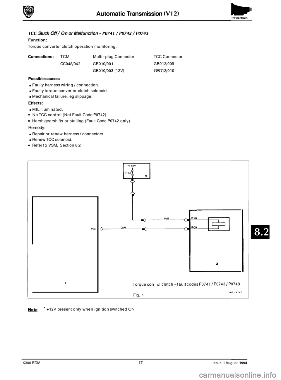
TCC Stuck Off / On or Malfunction - PO74 1 / PO742 / PO743
Function:
Torque converter clutch operation monitoring.
Connections: TCM Multi-plug Connector
CCO48/042 GBOlO/OO1
GB010/003 (12V)
Possible causes:
. Faulty harness wiring 1 connection.
. Faulty torque converter clutch solenoid.
. Mechanical failure, eg slippage.
Effects:
. MIL illuminated.
' No TCC control (Not Fault Code P0742).
Harsh gearshifts or stalling (Fault Code PO742 only).
Remedy:
. Repair or renew harness 1 connectors.
Refer to VSM, Section 8.2.
. Renew TCC solenoid. TCC
Connector
GBOl2/009
GBO 1210 10
PQ:
1 Torque con
Fig. 1
01 clutch -fault codes PO741 1 PO743 I PO748
J80 - IT47
Note: * +12V present only when ignition switched ON
X300 EDM 17 Issue 1 August 1994
Page 51 of 327
Automatic Transmission (V12) Powertrain
Shift Malfunction (Max- Adapt) - PO780
Function:
Transmission internal operation monitoring.
Possible causes:
. Mechanical wear 1 failure.
Effects:
. Harsher shifts.
Remedy:
. Refer to VSM, Section 8.2.
Transmission Component Slipping - PI 739
Function:
Transmission internal operation monitoring.
Possible causes:
Faulty harness wiring /connection.
. Fuse blown.
. Faulty torque converter clutch.
Mechanical wear.
Effects:
. MIL lamp illuminated.
. Harsh shifts.
Remedy:
. Repair or renew harness 1 connector.
Renew fuse F14 in LH heelboard fuse-box on determining reason for rupture.
Refer to VSM, Section 8.2.
0
0
Issue 1 August 1994 20 X300 EDM
Page 52 of 327
Automatic Transmission (V12) Powertrain
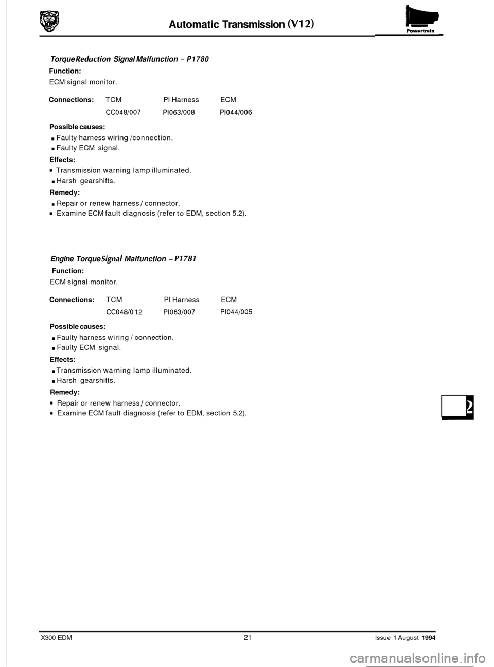
Torque Reduction Signal Malfunction - P1780
Function:
ECM signal monitor.
Connections: TCM PI Harness ECM
CC048/007 P1063/008 P1044/006
Possible causes:
. Faulty harness wiring /connection.
. Faulty ECM signal.
Effects:
. Harsh gearshifts.
Remedy:
. Repair or renew harness / connector.
Examine ECM fault diagnosis (refer to EDM, section 5.2).
Transmission
warning lamp illuminated.
Engine Torque Signal Malfunction - P1781
Function:
ECM signal monitor.
Connections: TCM PI Harness
CC048/0 12 P1063/007
ECM
P1044/005
Possible causes:
. Faulty harness wiring /connection.
. Faulty ECM signal.
Effects:
. Transmission warning lamp illuminated.
. Harsh gearshifts.
Remedy:
Repair or renew harness / connector.
Examine ECM fault diagnosis (refer
to EDM, section 5.2).
X300 EDM 21 Issue 1 August 1994
Page 53 of 327
Automatic Transmission (V12) W Powertrain
1
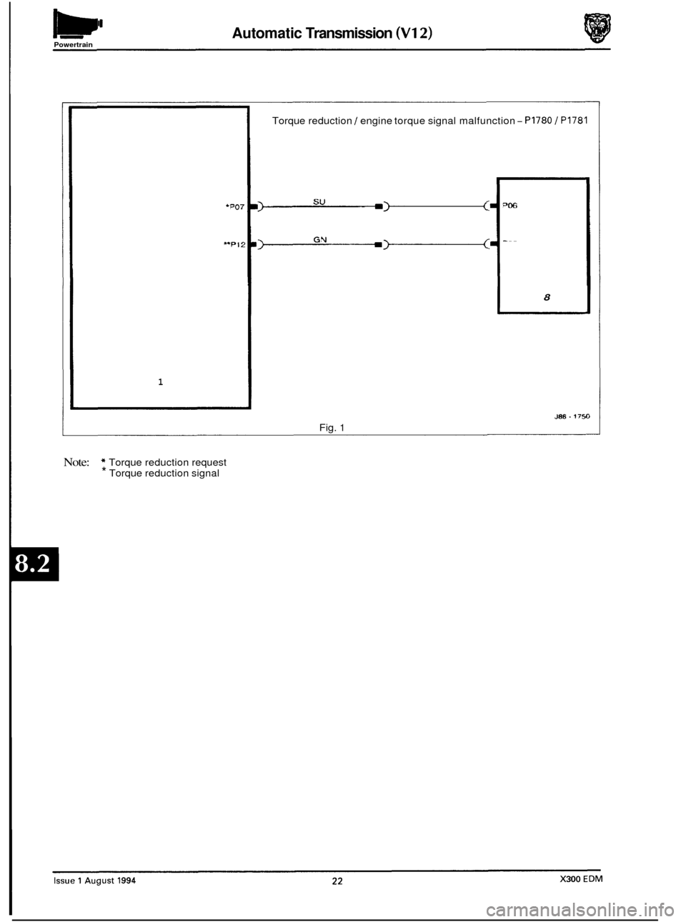
Torque reduction / engine torque signal malfunction - PI780 / PI781
-
8
J86.175~3
Fig. 1
Note: * Torque reduction request * Torque reduction signal
0
0
0
Page 109 of 327
Electrical rl
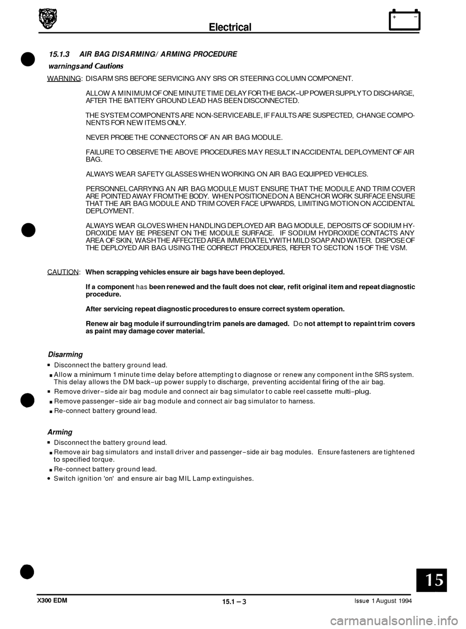
15.1.3 AIR BAG DISARMING/ ARMING PROCEDURE
warnings and cautions
WARNING: DISARM SRS BEFORE SERVICING ANY SRS OR STEERING COLUMN COMPONENT.
ALLOW A MINIMUM OF ONE MINUTE TIME DELAY FOR THE BACK
-UP POWER SUPPLY TO DISCHARGE,
AFTER THE BATTERY GROUND LEAD HAS BEEN DISCONNECTED.
THE SYSTEM COMPONENTS ARE NON
-SERVICEABLE, IF FAULTS ARE SUSPECTED, CHANGE COMPO- NENTS FOR NEW ITEMS ONLY.
NEVER PROBE THE CONNECTORS OF AN AIR BAG MODULE.
FAILURE TO OBSERVE THE ABOVE PROCEDURES MAY RESULT
IN ACCIDENTAL DEPLOYMENT OF AIR
BAG.
ALWAYS WEAR SAFETY GLASSES WHEN WORKING ON AIR BAG EQUIPPED VEHICLES.
PERSONNEL CARRYING AN AIR BAG MODULE MUST ENSURE THAT THE MODULE AND TRIM COVER
ARE POINTED AWAY FROM THE BODY. WHEN POSITIONED ON A BENCH
OR WORK SURFACE ENSURE
THAT THE AIR BAG MODULE AND TRIM COVER FACE UPWARDS, LIMITING MOTION ON ACCIDENTAL
DEPLOYMENT.
ALWAYS WEAR GLOVES WHEN HANDLING DEPLOYED AIR BAG MODULE, DEPOSITS OF SODIUM HY
- DROXIDE MAY BE PRESENT ON THE MODULE SURFACE. IF SODIUM HYDROXIDE CONTACTS ANY
AREA OF SKIN, WASH THE AFFECTED AREA IMMEDIATELY WITH MILD SOAP AND WATER. DISPOSE OF
THE DEPLOYED AIR BAG USING THE CORRECT PROCEDURES, REFER TO SECTION
15 OF THE VSM.
CAUTION:
When scrapping vehicles ensure air bags have been deployed.
If
a component has been renewed and the fault does not clear, refit original item and repeat diagnostic
procedure.
After servicing repeat diagnostic procedures to ensure correct system operation.
Renew air bag module if surrounding trim panels are damaged.
Do not attempt to repaint trim covers as paint may damage cover material.
Disarming
. Allow a minimum 1 minute time delay before attempting to diagnose or renew any component in the SRS system.
Remove driver-side air bag module and connect air bag simulator to cable reel cassette multi-plug.
. Remove passenger-side air bag module and connect air bag simulator to harness.
. Re-connect battery ground lead.
Disconnect
the battery ground lead.
This delay allows the DM back
-up power supply to discharge, preventing accidental firing of the air bag.
0
Arming
Disconnect the battery ground lead.
. Remove air bag simulators and install driver and passenger-side air bag modules. Ensure fasteners are tightened
. Re-connect battery ground lead.
Switch ignition 'on' and ensure air bag MIL Lamp extinguishes.
to specified torque.
X300 EDM 15.1 -3 Issue 1 August 1994