ECO mode JAGUAR XJ6 1994 2.G Electrical Diagnostic Manual
[x] Cancel search | Manufacturer: JAGUAR, Model Year: 1994, Model line: XJ6, Model: JAGUAR XJ6 1994 2.GPages: 327, PDF Size: 13.73 MB
Page 4 of 327
Automatic Transmission (AJ16) w
8.1.1 ZF 4HP 24 E TRANSMISSION, SYSTEM DESCRIPTION
The electronic transmission system fitted to normally aspirated 4.0 liter vehicles comprises the following components:
0 ZF 4HP 24 E Automatic Transmission
0 Rotary selector switch
0 Electronic Transmission Control Module
0 Decoder Module
0 Performance Mode Switch
0 Kickdown Switch
0 Gear Selection Illumination Module
System control is effected by the transmission control module (TCM), located behind the passenger side fascia, which
continuously monitors requests made by the drivervia the gearselector, throttle pedal etc. This data is used
inconiunc- tion with the speed input from the transmission and inputs from the engine management system, to calculate optimum
shift points and control parametersfor shift pressure and ignition retardation to enhance shift quality and reduce trans-
mission unit wear.
TheTCM is also able to detect faults within the system and store the relevant fault codes for interrogation with diagnos-
tic equipment.
Gear shifts are controlled by three solenoid valves, and
a pressure control regulator, located on the valve block within
the transmission unit assembly. If a serious fault occurs, the TCM removes all electrical power from these valves and
the transmission system reverts to a mechanical default condition. This condition allows only mechanical selection
of reverse and one forward gear, either third or fourth, depending on prevailing conditions at the time of the default.
The decoder module receives inputs from the rotary switch and decodes these to drive one of six possible outputs,
illuminating the correct gear indicator on the gear selector illumination module.
The performance mode switch and kick
-down switch are used to adjust transmission operation as required by the
driver. Performance mode selection, made via a switch mounted on the gear selector mechanism surround, can be
either NORMAL, for everyday use, or SPORT, for enhanced performance. Kick
-down is activated by a switch mounted
below the accelerator pedal and is used to initiate a downward gear change, increasing torque and acceleration.
8.1.2 COMPONENT DESCRlPTIONS
Transmission Unit
The ZF 4HP 24 E automatic transmission unit houses the three solenoid valves which control gear shifts. A pressure
control valve is also located on the solenoid valve block. These four valves initiate and control shift patterns within
the transmission unit by regulating fluid flow.
Rotary Selector Switch
The seven position rotary gear selector switch is mounted on the LH side of the transmission unit and indicates gear
selection to the TCM and decoder module.
Transmission Control Module
The electronic transmission control module regulates gear changes by controlling the operation of the transmission
unit solenoid valves, and monitoring the state of other vehicle systems which have an effect on torque demand, vehicle
speed etc. The module also interfaces with the engine management system, climate control system, body processor
unit and ABS
I traction control system.
Connections from the TCM are listed on the following page.
X300 EDM 1 Issue 1 August 1994
Page 19 of 327
Automatic Transmission (AJ16)
TORQUE REDUCTION SIGNAL - P 1780
The diagnostic for this signal is based entirely on feedback from the ECM. If the torque reduction request is active for
greater than 2 seconds, the ECM starts the torque reduction fault timeout (IO seconds). If the signal returns to the
standby condition within this time, the timeout is reset. If the timeout matures then the ECM stores a fault code and
transmits 93% on the torque signal line and also lights the MIL where necessary.
The ECM will also initiate the torque reduction fault timeout
if the signal line is permanently high or low for greater
than 125ms. The conditions for resetting the timeout and the actions if the timeout matures are the same as previously
described above. When the TCM receives the correct indication on the torque signal line, this fault code will be stored
and
a substitute function will be adopted and the warning lamp will be illuminated. The engine management will send
normal torque signal when the torque reduction signal returns to standby or when the ignition is reset.
This torque reduction signal is used during gearshifts to conveythe actual amount of retard to be applied to the ignition
advance angle
afterthe other trims. The signal idles at 17% (or 12% if theTCM wishes to drive the MIL on), and changes
to 20% at the start of a gearshift. This represents 0" retard. When an amount of retard is required, the PWM will increase
to the desired value (between 20% and 90%) and return to 20% and then to idle state at the end of the shift.
TCM
PI HARNESS ECM
CC007/032 P1063/008 P1105/026
TORQUE SIGNAL MALFUNCTION - P 1781
The torque signal is a PWM signal from the ECM to the TCM which conveys information about the actual torque devel- oped by the engine in the range 0 to 510Nm. The base frequency is 91Hz and the signal which is active low should be
within the range 10% to 90% modulation. The torque signal is monitored continuously during initialization and oper
- ation. If the frequency of the signal is incorrect or the signal is out of range, then this fault code will be flagged. The
TCM will adopt a substitute function and the warning lamp will be illuminated. This fault code will only be flagged if the engine speed is above 448 rpm.
TCM
PI HARNESS ECM
CC007/02 1 P1063/007 PI 105/033
Possible causes:
. Faulty harness wiring I connector.
. Faulty signal from ECM.
Effects:
. Transmission warning lamp illuminated.
Substitute torque signal adopted by TCM.
. =Normal mode only available.
. No kickdown facility.
. Maximum fluid pressure applied.
Remedy:
. Repair or renew harness / connector.
Examine ECM fault diagnosis (refer to EDM, section 5.1).
Issue 1 August 1994 16 X300 EDM
Page 24 of 327
Automatic Transmission (AJ16)
TP ELECTRICAL SIGNAL SYSTEM - P 1791
If the throttle angle signal line is held permanently high or low for more than looms, then this fault will be recognised
and stored. The TCM will adopt the substitute throttle value and turn on the warning lamp. The fault code will only be
stored if the engine speed is greater than 400rpm.
TCM PI HARNESS ECM
CC007/047 P1063/00 1 PI 1041032
Possible causes:
Faulty harness wiring I connection.
. Faulty ECM signal.
Effects:
Transmission warning lamp illuminated.
. MIL illuminated.
Normal mode only available.
Substitute throttle angle adopted.
No kickdown facility.
Remedy:
Repair or renew harness 1 connector.
Examine ECM fault diagnosis (refer to EDM, Section 5.1).
TP SIGNAL SYSTEM RANGE/ PERFORMANCE - P 1790
The throttle signal is a pulse width modulated (pwm) input which runs at a constant frequency of 183 Hz the information is contained in the duty cycle of the signal. If this information is out of range, that is, the duty cycle is less than 5% or
greater than 94%, then the TCM will use a substitute throttle value of 47% and will light the warning lamp and this fault code will be stored. During cranking, this signal is used to convey the engine coolant temperature. The coolant tem- perature signal persistsfor 500 msec after reaching the engine run threshold of 400 rpm. If theTCM does not recognise a valid throttle angle signal afterthis time then a substitute throttle value (47%) will be used and the warning lamp will
be
lit and this fault code will be stored. A fault code will only be stored if the engine speed is greater than 400 rpm. If an out of range coolant temperature is received then a substitute coolant temperature value (77" C) is used but no fault is stored.
X300 EDM 21 Issue 1 August 1994
Page 32 of 327
Automatic Transmission (V12) Powertrain
8.2.1 POWERTRAIN
41-80-E TRANSMISSION, SYSTEM DESCRIPTION
The electronic transmission system fitted to 6.0 liter and 4.0 liter super-charged vehicles comprises the following com- ponents:
0 Hydra-matic 4L-80-E Automatic Transmission
0 Electronic Transmission Control Module
0 Performance Mode Switch
0 Kickdown Switch
0 Gear Selection Module (illuminated)
System control is effected by the transmission control module
(TCM), located behind the passenger side fascia, which continuously monitors requests made bythe driver via the gearselector, throttle pedal etc. This data is used inconjunc- tion with the speed input from the transmission and inputs from the engine management system, to calculate optimum
shift points and control parametersfor shift pressure and ignition retardation to enhance shift quality and reduce trans- mission unit wear.
TheTCM is also able to detect faults within the system and store the relevant fault codes for interrogation with diagnos- tic equipment.
Gear shifts are controlled
by three solenoid valves, and a pressure control regulator, located on the valve block within
the transmission unit assembly. If a serious fault occurs, the TCM removes all electrical power from these valves and
the transmission system reverts to a mechanical default condition. This condition allows only mechanical selection
of reverse and one forward gear, either
third or fourth, depending on prevailing conditions at the time of the default.
The performance mode switch and kick
-down switch are used to adjust transmission operation as required by the
driver. Performance mode selection, made via a switch mounted on the selector switch surround, can be either NOR- MAL, for everyday use, or SPORT, for enhanced performance. Kick-down is activated by a switch mounted below the
accelerator pedal and is used to initiate a downward gear change, increasing torque and acceleration.
8.2.2 COMPONENT DESCRIPTIONS
Transmission Unit
The powertrain 4L-80-E transmission unit houses the two solenoid valves which control gear shifts. A pressure control
valve is also located on the solenoid valve block. These three valves initiate and control shift patterns within the trans- mission unit by regulating fluid flow.
Performance Mode Switch
The two position performance mode switch allows selection of 'sport' or 'normal' mode as required by the driver. The
switch input to TCM causes a gear shift pattern change so that gear shifts take place at higher engine revs, enhancing
performance, when in 'sport' mode. For everyday use, 'normal' mode utilises a shift pattern for optimum driver com- fort.
Kickdown Switch
The 'kick-down' facility is activated when full downward travel of the accelerator pedal occurs.
Activation of the switch provides a signal to TCM indicating that greater acceleration, and hence downward gear shifts
are required. Switch height is adjustable
so that kick-down can be achieved at a pre-determined throttle opening.
Gear Selection Illumination Module
This module is located above the gear selector mechanism and its sole purpose is to display the selected gear (in red)
on receipt of a signal from the decoder module.
X300 EDM 1 Issue 1 August 1994
Page 36 of 327
Automatic Transmission (V12) Powertrain
8.2.3 OPERATING PRlNClPL ES
The electronic control system is split into four main functional areas:
0 Shift Point Control
0 Lock-up Control
0 Pressure Modulation
0 Engine Torque Control
0
Shift Point Control
The optimum gear ratio is selected as a function of transmission output speed, engine load, position of selector switch
and program switch.
Lock-up Control
The torque converter clutch is engaged as a function of load, output speed, gear selected and drive program. Lock-up
is possible in second, third and fourth gear. Apply and release quality is controlled by the pulse width modulated pres-
sure regulator solenoid.
Pressure Modulation
Hydraulic pressure in the transmission shift friction elements is accurately matched to transmission output torque
using an electrically operated solenoid valve to control pressure level. Transmission input torque is calculated from
an output torque value, supplied by EMS, and converter slip.
Engine Torque Control
Engine torque control reduces the energy dissipated within the system during gear shifts. The effect of this control
increase the transmission service life by reducing slippage time, increases comfort by reducing clutch torque trans- mission and allows a greater transfer of power by the transmission unit.
8.2.4 INPUTS / OUTPUTS
8.2.4.1 INPUTS
Transmission Range
The transmission range is detectec ,ythe pressureswitch manifold located within the transmission unit. The manifold
transmits a coded message to the TCM indicating gear selector position.
Performance Mode Select
Performance mode select uses a two wire input to the TCM allowing selection of different transmission operating
modes.
Line A; Used for selection of traction control shift pattern and controlled
by the ABS /TC CM.
Line
B; Used for selection of 'Normal' or 'Sports' mode, manually selected at a two position rocker switch mounted
on the gear selector unit. Switch resistance is equal to or greaterthan look$, open circuit and equal to or less than 0.5$ closed circuit, measured across contacts at a current of 10mA.
Kickdown Switch
This signal is controlled by the operation ofthe kickdown switch on depression of the accelerator pedal to its full extent.
The switch remains in 'normally open' position until contact with the pedal closes the contacts. Switch resistance is
equal to or greater than look$, open circuit, and equal to or less than 0.5$ closed circuit, measured across contacts at
a current of
10Ma.
Calibration Select
The calibration select input allows identification of different vehicle specifications, ie 4.0 liter supercharged, or 6.0 liter (V12). The link, to ground, from the TCM is either short or open circuit, dependant upon internal software calibration
for each vehicle variant.
X300 EDM 5 Issue 1 August 1994
Page 38 of 327
Automatic Transmission (V12) ~ Pow. rtrain
Engine
Torque Reduction and Malfunction Indication
This signal, to the ECM, has three modes of operation.
1. To indicate normal engine operation to the ECM.
2. During gearshifts, to request reduction of engine torque
3. During fault conditions, to inform the ECM.
During normal operation
theTCM outputs a constant duty cycle signal to the ECM. The signal is changed when torque
reduction is required to indicate to the ECM the degree of ignition retardation necessary. If a fault condition, relating
to OBD
II CARB legislation, occurs the TCM will transmit a signal to the ECM relating this event. The ECM will only
respond to this signal if its duration is 100 milli-seconds or longer.
If the signal from the torque reduction line is either HIGH or LOW for 2 or more seconds the EMS will recognise that
a fault may be present and transmit this information to the TCM.
If the signal from the torque reduction line lasts for 2 or more seconds the EMS will return to normal operation.
Sport Mode Indicator Lamp
The sport mode indicator lamp, mounted on the instrument panel, is illuminate when sport mode is selected and the
ignition switch is ON. Sport mode is selected at a two position switch mounted to the rear of the gear selector assembly.
Gearbox Failure Warning Lamp
The gearbox failure warning lamp, mounted on the instrument panel, is illuminated when afault is detected bytheTCM within the transmission electrical or mechanical systems.
Vehicle Speed (12 cylinder vehicles only)
This output signal is calculated from the transmission output speed and supplied to the ECM as an indication of vehicle
speed.
8.2.5 DIAGNOSTIC LINKS
Diagnostic
L line
One of a two wire interface used to activate stored diagnostic codes for reading by external equipment.
Diagnostic K Line
One of a two-wire interface used to communicate stored diagnostic codes for reading by external diagnostic equip- ment.
X300 EDM 7 Issue 1 August 1994
Page 45 of 327
Automatic Transmission (V12) Powertrain
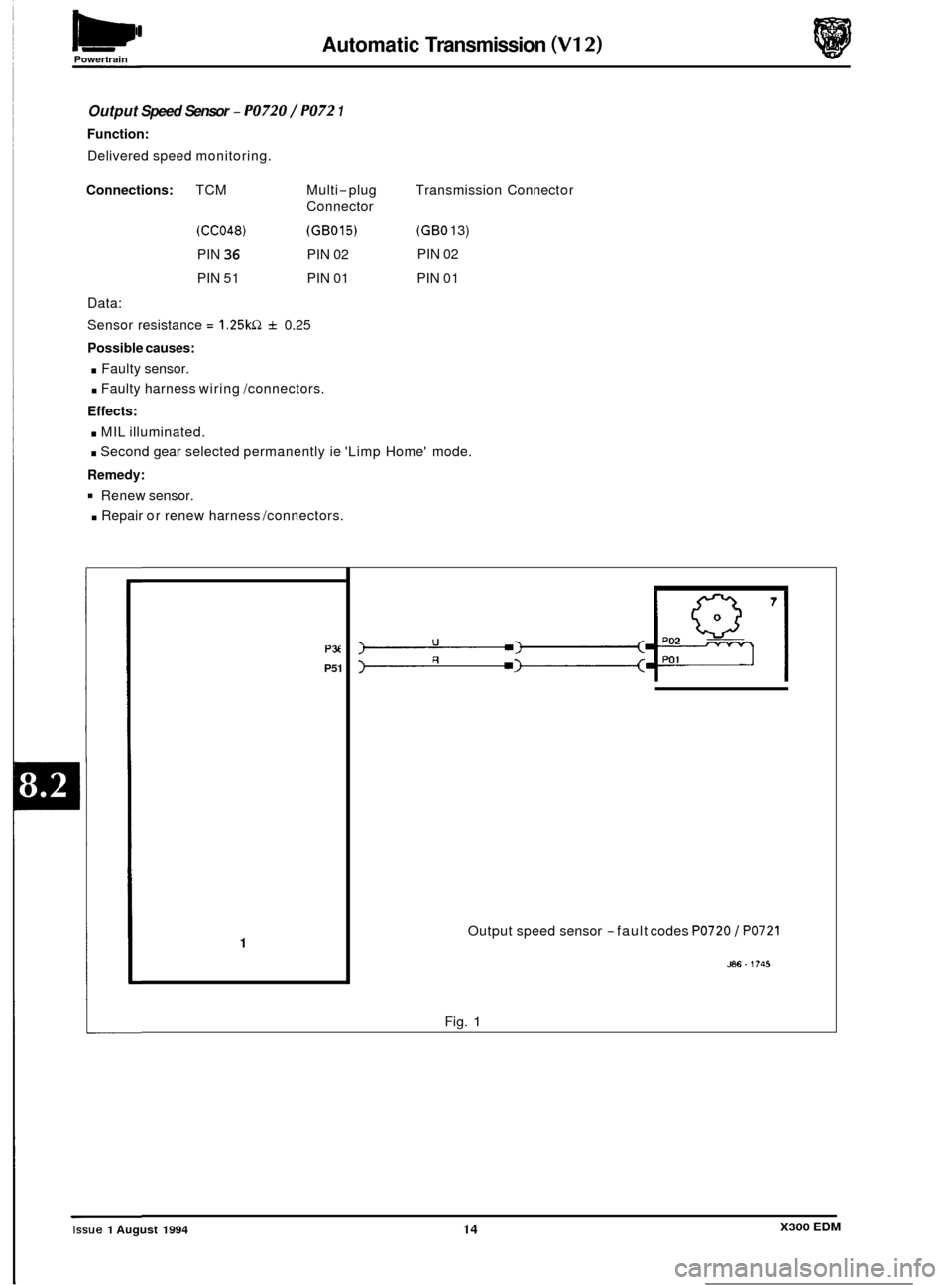
Output Speed Sensor - PO720 / PO72 1
Function:
Delivered speed monitoring.
Connections: TCM Multi-plug
Connector
(CC048) (GB015)
PIN 36 PIN 02
PIN
51 PIN 01
Data:
Sensor resistance = 1.25kQ f 0.25
Possible causes:
. Faulty sensor.
. Faulty harness wiring /connectors.
Effects:
. MIL illuminated. Transmission
Connect or
(GBO 13)
PIN 02
PIN 01
. Second gear selected permanently ie 'Limp Home' mode.
Remedy:
. Repair or renew harness /connectors.
Renew
sensor.
PX
P51
1 Output speed sensor -fault codes PO720 / PO721
586. 1?45
Fig. 1
0
0
0
X300 EDM Issue 1 August 1994 14
Page 50 of 327
Powertrain Automatic Transmission (V12)
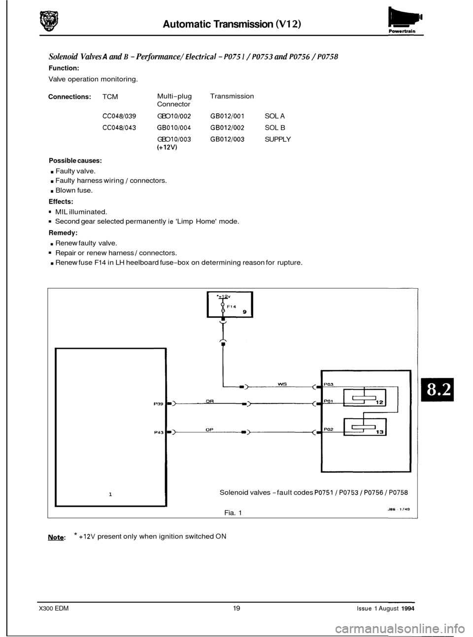
Solenoid Valves A and B - Performance /Electrical - PO75 1 / PO753 and PO756 / PO758
Function:
Valve operation monitoring.
Connections: TCM
CCO48/039
CCO48/043
Multi-plug
Connector
GBO
10/002
GBOl0/004
GBO 10/003
(+12V)
Transmission
GB012/001 SOL A
GBOl2/002 SOL B
GB012/003 SUPPLY
Possible causes:
. Faulty valve.
. Faulty harness wiring 1 connectors.
. Blown fuse.
Effects:
9 MIL illuminated.
Second gear selected permanently ie 'Limp Home' mode.
Remedy:
. Renew faulty valve.
Repair or renew harness 1 connectors.
. Renew fuse F14 in LH heelboard fuse-box on determining reason for rupture.
1 1
Solenoid valves -fault codes PO751 / PO753 / PO756 / PO758
1
Fia. 1 JUl3 ~ 1749
&@: * +12V present
only when ignition switched ON
X300 EDM 19 Issue 1 August 1994
Page 56 of 327
Automatic Transmission (V12) - Powertrain
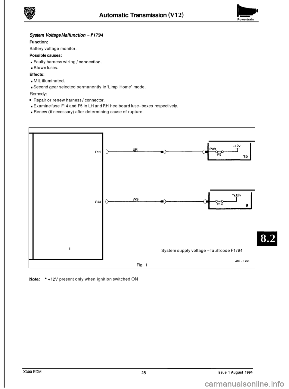
System Voltage Malfunction - P1794
Function:
Battery voltage monitor.
Possible causes:
. Faulty harness wiring /connection.
. Blown fuses.
Effects:
. MIL illuminated.
. Second gear selected permanently ie ‘Limp Home’ mode.
Remedy:
Repair or renew harness I connector.
. Examine fuse F14 and F5 in LH and RH heelboard fuse-boxes respectively.
. Renew (if necessary) after determining cause of rupture.
P5 5
P53
1
I -3---+-2 YR
System supply voltage -fault code PI794
J86 - 1 753 Fig. 1
- Note: * +12V present only when ignition switched ON
X300 EDM ~.
25 Issue 1 August 1994
Page 79 of 327
Climate Control Systems
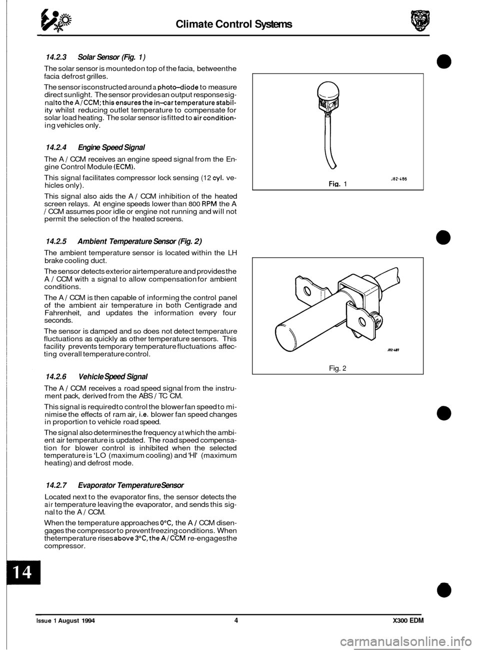
14.2.3 Solar Sensor (Fig. 1)
The solar sensor is mounted on top of the facia, between the
facia defrost grilles.
The sensor isconstructed around
a photo-diode to measure
direct sunlight. The sensor provides an output response sig-
nal totheA1CCM;thisensuresthe in-cartemperaturestabil- ity whilst reducing outlet temperature to compensate for
solar load heating. The solar sensor is fitted to aircondition- ing vehicles only.
14.2.4 Engine Speed Signal
The A 1 CCM receives an engine speed signal from the En- gine Control Module (ECM).
This signal facilitates compressor lock sensing (12 cyl. ve- hicles only).
This signal also aids the A
1 CCM inhibition of the heated
screen relays. At engine speeds lower than 800 RPM the A I CCM assumes poor idle or engine not running and will not
permit the selection of the heated screens.
14.2.5 Ambient Temperature Sensor (Fig. 2)
The ambient temperature sensor is located within the LH
brake cooling duct.
The sensor detects exterior airtemperature and provides the
A
I CCM with a signal to allow compensation for ambient
conditions.
The A
1 CCM is then capable of informing the control panel of the ambient air temperature in both Centigrade and
Fahrenheit, and updates the information every four
seconds.
The sensor is damped and
so does not detect temperature
fluctuations as quickly as other temperature sensors. This
facility prevents temporary temperature fluctuations affec
- ting overall temperature control.
14.2.6 Vehicle Speed Signal
The A 1 CCM receives a road speed signal from the instru- ment pack, derived from the ABS 1 TC CM.
This signal is required to control the blower fan speed to mi
- nimise the effects of ram air, i.e. blower fan speed changes
in proportion to vehicle road speed.
The signal also determines the frequency
at which the ambi- ent air temperature is updated. The road speed compensa-
tion for blower control is inhibited when the selected
temperature is 'LO (maximum cooling) and 'HI' (maximum
heating) and defrost mode.
14.2.7 Evaporator Temperature Sensor
Located next to the evaporator fins, the sensor detects the air temperature leaving the evaporator, and sends this sig- nal to the A 1 CCM.
When the temperature approaches
OOC, the A 1 CCM disen-
gages the compressor to prevent freezing conditions. When
thetemperature rises above3OC.theAlCCM re-engagesthe
compressor.
J82-L06 Fig. 1
Fig. 2
0
0
Issue 1 August 1994 4 X300 EDM