JAGUAR XJ6 1994 2.G Electrical Diagnostic Manual
Manufacturer: JAGUAR, Model Year: 1994,
Model line: XJ6,
Model: JAGUAR XJ6 1994 2.G
Pages: 327, PDF Size: 13.73 MB
JAGUAR XJ6 1994 2.G Electrical Diagnostic Manual
XJ6 1994 2.G
JAGUAR
JAGUAR
https://www.carmanualsonline.info/img/21/7689/w960_7689-0.png
JAGUAR XJ6 1994 2.G Electrical Diagnostic Manual
Trending: height adjustment, wheel torque, ESP, fold seats, key battery, radio, oil pressure
Page 231 of 327
Electrical rl
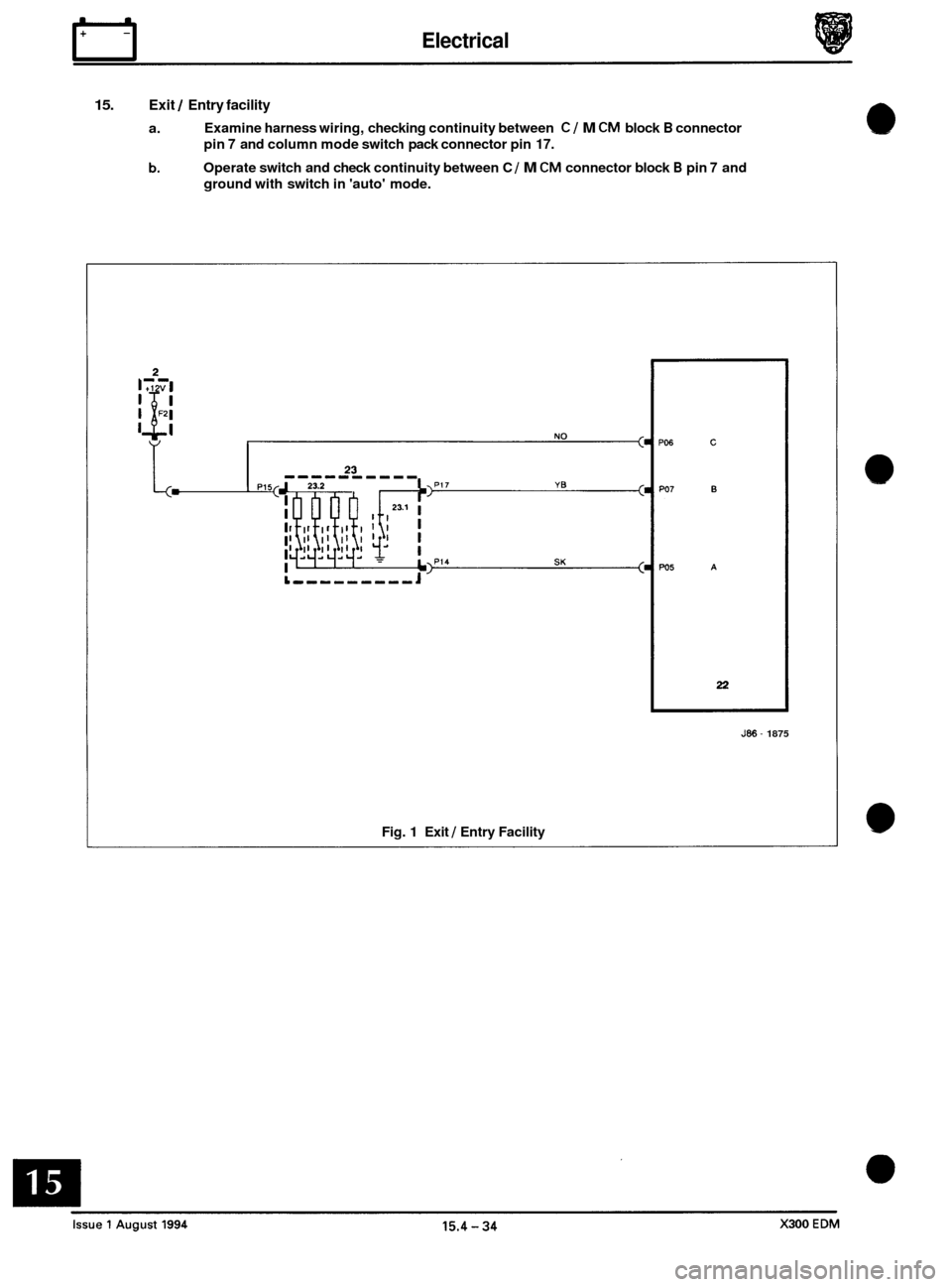
15. Exit / Entry facility
a.
b.
Examine harness wiring, checking continuity between C/ M CM block B connector
pin
7 and column mode switch pack connector pin 17.
Operate switch and check continuity between C / M CM connector block B pin 7 and
ground with switch in 'auto' mode.
J86 - 1875
Fig. 1 Exit 1 Entry Facility
Page 232 of 327
E I ect r ica I rl
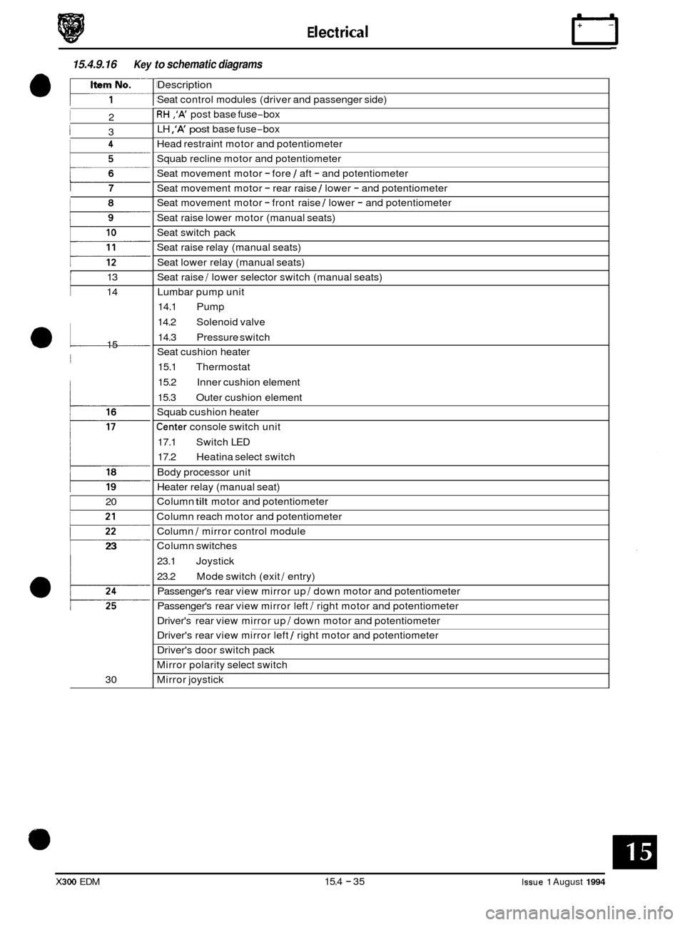
15.4.9.16 Key to schematic diagrams
I 2
I 3
i 7
, I 13
14
a1 15
j
20
p
23
30
Description
Seat control modules (driver and passenger side)
RH ,'A' post base fuse-box
LH
,'A' post base fuse-box
Head restraint motor and potentiometer
Squab recline motor and potentiometer
Seat movement motor
- fore 1 aft - and potentiometer
Seat movement motor
- rear raise 1 lower - and potentiometer
Seat movement motor
- front raise 1 lower - and potentiometer
Seat raise lower motor (manual seats)
Seat switch pack
Seat raise relay (manual seats)
Seat lower relay (manual seats)
Seat raise
/ lower selector switch (manual seats)
Lumbar pump unit
14.1 Pump
14.2 Solenoid valve
14.3 Pressure switch
Seat cushion heater
15.1 Thermostat
15.2 Inner cushion element
15.3 Outer cushion element
Squab cushion heater
Center console switch unit
17.1 Switch LED
17.2 Heatina select switch
Body processor unit
Heater relay (manual seat)
Column
tilt motor and potentiometer
Column reach motor and potentiometer
Column
I mirror control module
Column switches
23.1 Joystick
23.2 Passenger's rear view mirror up
I down motor and potentiometer
Passenger's rear view mirror left
I right motor and potentiometer
Mode switch (exit
I entry)
Driver's rear view mirror up
I down motor and potentiometer
Driver's rear view mirror left
1 right motor and potentiometer
Driver's door switch pack
Mirror polarity select switch
Mirror joystick
X300 EDM 15.4 - 35 Issue 1 August 1994
Page 233 of 327
E I ect r ica I
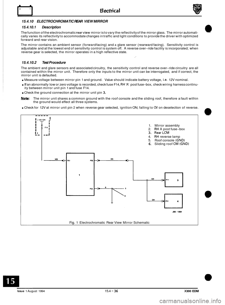
15.4.10 ELECTROCHROMATIC REAR VIEW MIRROR
15.4.10.1 Description
The function of the electrochromatic rearview mirror is to vary the reflectivity of the mirror glass. The mirror automati- cally varies its reflectivity to accommodate changes in traffic and light conditions to provide the driver with optimized
forward and rear vision.
The mirror contains an ambient sensor (forward facing) and
a glare sensor (rearward facing). Sensitivity control is
adjustable and at the lowest end of sensitivity control is system off. A reverse over-ride facility is incorporated; when
reverse gear is selected, the mirror operates in a high reflective state.
15.4.10.2 Test Procedure
The ambient and glare sensors and associated circuitry, the sensitivity control and reverse over-ride circuitry are all
contained within the mirror unit. Therefore only the inputs to the mirror unit can be interrogated, and if correct, the
mirror unit is defaulted.
. Measure voltage between mirror pin 1 and ground. Value should indicate battery voltage, i.e. 12V nominal.
. If an abnormally low or zero voltage is recorded, check fuse F14, RH 'A' post fuse-box, check wiring harness continu-
. Check the ground connection at the mirror unit pin 3.
Note: The mirror unit shares a common ground with the roof console and the sliding roof, therefore a fault within
the ground would effect all three systems.
. Check for 12V at mirror unit pin 2 when reverse gear selected, ignition ON; falling to OV on deselection of reverse.
/
ity between mirror unit pin 1 and fuse F14.
----- I +12VIGN ! I I I
I
L',
I I
I ,,J
F14 1. Mirror assembly
2. RH A post fuse-box
3. RearLCM
4. RH reverse lamp
5. Roof console (GND) 6. Sliding roof CM (GND)
J86-1864
Fig. 1 Electrochromatic Rear View Mirror Schematic
Issue 1 August 1994 15.4 - 36 X300 EDM
Page 234 of 327
A E C D E F
ABSiTC CM 12 1
I UOJOIR
e
e
a
L70pF
IP
I
7
T
I
T[
j12 5
v
I
X300 EDM Issue 1 August 1994
Page 235 of 327
0 0
0
Circuit Diagrams ~~
~
DEC 1157
06 OF 6A
SCMD
15 5 3
r
%?
Issue 2 1 August 1994
Page 236 of 327
G NO
DEC 1157 LLTN. 090' 68 I
Circuit Diagrams
1
BPU
1
4 Y BRool'oo'
15.6.6.1
r- ! FC129 I I I I/
15.9.14
10~1001 -. 10711007 -. 1562
i15642 j15631 ,
-. IIOPOOM 1 4
-4 !SO751001
506 - c
R R I
Page 237 of 327
Circuit Diagrams
A I B I C I D I E A F I B I H I J I K I
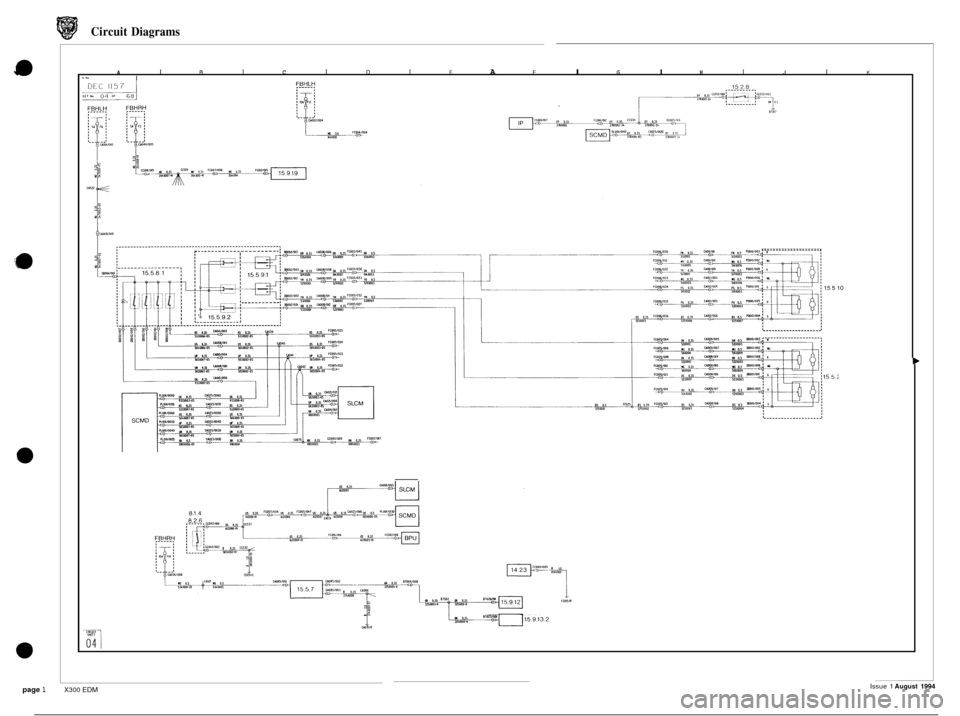
.___________________.
15 5 10 ~~
Issue 1 August 1994 page 1 X300 EDM
Page 238 of 327
DEL 1157
, - -. - - - -. !T!
Circuit Diagrams
FBHRH~ 0 a-
._.
.____..________, WI l.0 Y5Lw3
I Ccolllt
1 (XI05 W8WM so 0.35 01Mm I
SLCM 15.7.20
'I
L
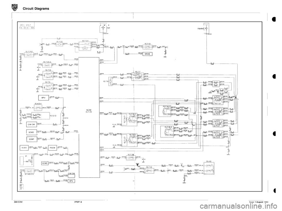
I
_. .
Page 4 300 EDM Issue 1 August 1994
Page 239 of 327
Circuit Diagrams
EJPU 15.10.1 a7Cb
3101017 ,OllR
1510 7.3 j
i COO2IW2
f(w11002
0011007
1
DO21033 ,
m1005
\I cmiwox) +-
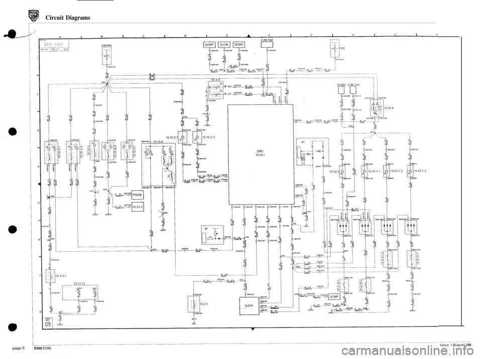
'--
1 Issue 1 August 1994 X300 EDM
Page 240 of 327
Circuit Diagrams
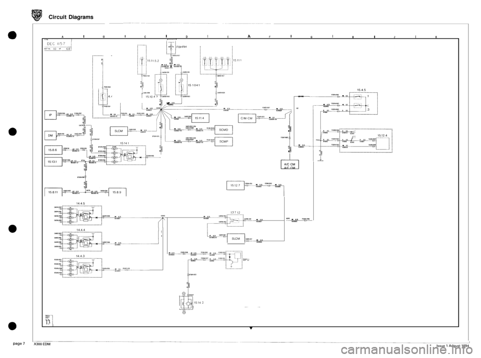
I A 0 C D E F I I I I A I I G H I J I K G No , - - - - - .
1041 PllOUW2 --. I C10111008
15.10 U 0.5 OPIWZ
i02
j$ , Y 0.13 I € Oy11Ol1
U 0.5 018zon-U
w 0.15 OJ8WO1
b LcolllOO3
El AIC CM
14.4.5
15 7 12
14.4.4 I
1'
@[ 15.14 2
!
'-a----: 7
13 I I v
Trending: fuel pump, airbag off, OBD port, remote control, washer fluid, seat adjustment, transmission
