check engine light JAGUAR XJ6 1994 2.G Electrical Diagnostic Manual
[x] Cancel search | Manufacturer: JAGUAR, Model Year: 1994, Model line: XJ6, Model: JAGUAR XJ6 1994 2.GPages: 327, PDF Size: 13.73 MB
Page 92 of 327

Climate Control Systems
14.7.6 FaulfCode21
Solar Sensor
0 Sensor, harness or A / CCM open circuit.
0 Sensor, harness or A / CCM short circuit to ground.
The sensor provides a linear output response signal to
pin 35 (16-way connector) A/ CCM; the output ranges from 0 to 5 volts, the voltage will drop as light intensity increases.
A resistance check can be carried out on the sensor and should conform with the figures below:
With no light on the sensor, the resistance should read approximately 15
kL2.
With increasing light intensity, the resistance should decrease from 15 kQ.
Inspect the sensor harness for open circuit or short circuit to ground. Rectify as necessary.
If the sensor and harness appear correct, suspect the A/ CCM.
14.7.7 Fadf Code 22
Compressor lock Signal
(12 cy/. vehicles only)
0 Sensor, harness or A / CCM open circuit.
0 Sensor, harness or A/ CCM short circuit to ground.
The compressor lock sensor provides an
a.c. signal proportional to engine speed. As engine speed increases the a.c. signal voltage value will increase.
A voltage checkcan be carried out on the sensor and should read approximately 0.5V a.c. whilst the compressor is ON and OV whilst the compressor is OFF, measured between pin 26 (12-way connector) and pin 19 (22-way connector) A
/ C CM.
If the reading is OV whilst the compressor is ON, suspect the sensor or the sensor harness (open circuit or short circuit
to ground).
Check the resistance between pins 1 and 2 of the compressor lock sensor, value should be
190a & 20%.
If the resistance measured falls outside the limits, renew the compressor lock sensor.
Inspect the sensor harness for open circuit or short circuit to ground. Rectify as necessary.
If the sensor and harness appear correct, suspect the AI CCM.
X300 EDM 17 Issue 1 August 1994
Page 156 of 327

Electrical IT
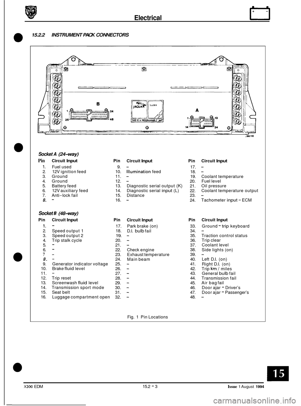
15.2.2 INSTRUMENT PACK CONNECTORS
0
Socket A (24-way)
Pin Circuit Input
1. Fuel used 2. 12V ignition feed 3. Ground 4. Ground 5. Battery feed 6. 12V auxiliary feed 7. Anti-lock fail 8. -
Socket 6 (48-way)
Pin Circuit Input
1. - 2. Speed output 1
3. Speed output 2
4. Trip stalk cycle 5. - 6. - 7- 8. - 9. Generator indicator voltage 10. Brake fluid level 11. - 12. Trip reset 13. Screenwash fluid level 14. Transmission sport mode 15. Seat belt 16. Luggage compartment open
Pin
9.
10.
11.
12.
13.
14.
15.
16.
Pin
17.
18.
19. 20.
21.
22.
23.
24.
25.
26.
27.
28.
29.
30.
31.
32.
Circuit Input
Illumination feed
-
- -
Diagnostic serial output (K) Diagnostic serial input (L)
Distance
-
Circuit Input
Park brake (on)
D.I.
bulb fail - - -
Check engine
Exhaust temperature
Main beam
- - - - - - - -
Fig. 1 Pin Locations
Pin
17.
18.
19.
20.
21.
22.
23.
24.
Pin
33.
34. 35.
36.
37.
38.
39. 40.
41.
42.
43.
44.
45.
46.
47.
48.
Circuit Input
-
Coolant temperature
Fuel level
Oil pressure
Coolant temperature output
Tachometer
input - ECM
-
Circuit Input
Ground - trip keyboard
Traction control status
Trip clear
Coolant level
Side lights (on)
Left D.I. (on)
Right D.I. (on)
Trip
km / miles
General bulb fail
Transmission fail
Air bag fail
Door ajar
- Driver’s
Door ajar - Passenger’s
-
X300 EDM 15.2 - 3 Issue 1 August 1994
Page 157 of 327

E I ect r ical
15.2.3 COMPONENT DESCRIPTION
15.2.3.1 Speedometer
The speed indication input signal, sent as a pulse rate, is generated by an open collectortransistor within the ABS con- trol module. The instrument pack converts the frequency of this signal to drive the speedometer and to provide two
road speed outputs:
Speed output
1 (pin 2,48 way connector)
This output is connected to the radio head unit, security control module and the power steering module.
Speed output 2 (pin
3,48 way connector)
This output is connected to the body processor unit, cruise control control module, air conditioning control module
and the engine management system.
15.2.3.2 Tachometer
The tachometer input, all engine variants, is provided by the engine management control module. When the engine
is running the control module generates three high state pulses per engine revolution.
15.2.3.3
This signal comes direct from the variable resistance type oil pressure sensor, mounted on the engine. The sensor
resistance values range from 75Q (8 Bar) to 330Q (0 Bar).
When the gauge reaches
a pre-determined reading the instrument pack illuminates the warning light.
Engine Oil Pressure and Warning lamp
15.2.3.4 Engine Coolant Temperature
This signal comes direct from the coolant temperature sensor (variable resistance type), mounted on the engine. The
sensor resistance values range from 34Q (hot) to 241Q (cold), when disconnected from the vehicle.
Note: The coolant temperature gauge is calibrated to indicate at approximately 'Normal' for a wide range of normal
engine operating temperatures.
15.2.3.5 Fuel Tank level Gauge and Warning lamp
This signal (pin 20,24-way connector) comes direct from the variable resistor type fuel level sensor. The sensor resis- tance values range from 80 ohms (full tank) to 900 ohms (empty tank).
When the gauge reaches a pre
-determined reading, the instrument pack illuminates the warning lamp.
15.2.3.6
Battery voltage is displayed on the gauge by measuring the ignition voltage.
The red charge warning lamp will illuminate if either the voltage is too low (below
10.5V) or too high (above 15.5V). In addition, the generator provides a low signal to the instrument pack (pin 9,48-way connector) when battery charging
is unsatisfactory.
Battery Voltage Gauge and Warning lamp
15.2.3.7 Liquid Crystal Display
A single line, six digit, 7 segment display with six trip function flags used for odometer, trip computer and driver mess- ages.
!Y,Q&: If the instrument pack has not been PECUS programmed, the back illumination of the LCD will not switch on.
Check that a PECUS label is attached to the back of the pack.
Issue 1 August 1994 15.2 - 4 X300 EDM