brake sensor JAGUAR XJ6 1994 2.G User Guide
[x] Cancel search | Manufacturer: JAGUAR, Model Year: 1994, Model line: XJ6, Model: JAGUAR XJ6 1994 2.GPages: 521, PDF Size: 17.35 MB
Page 229 of 521

12.1.5. ABS Components
Hydraulic Module
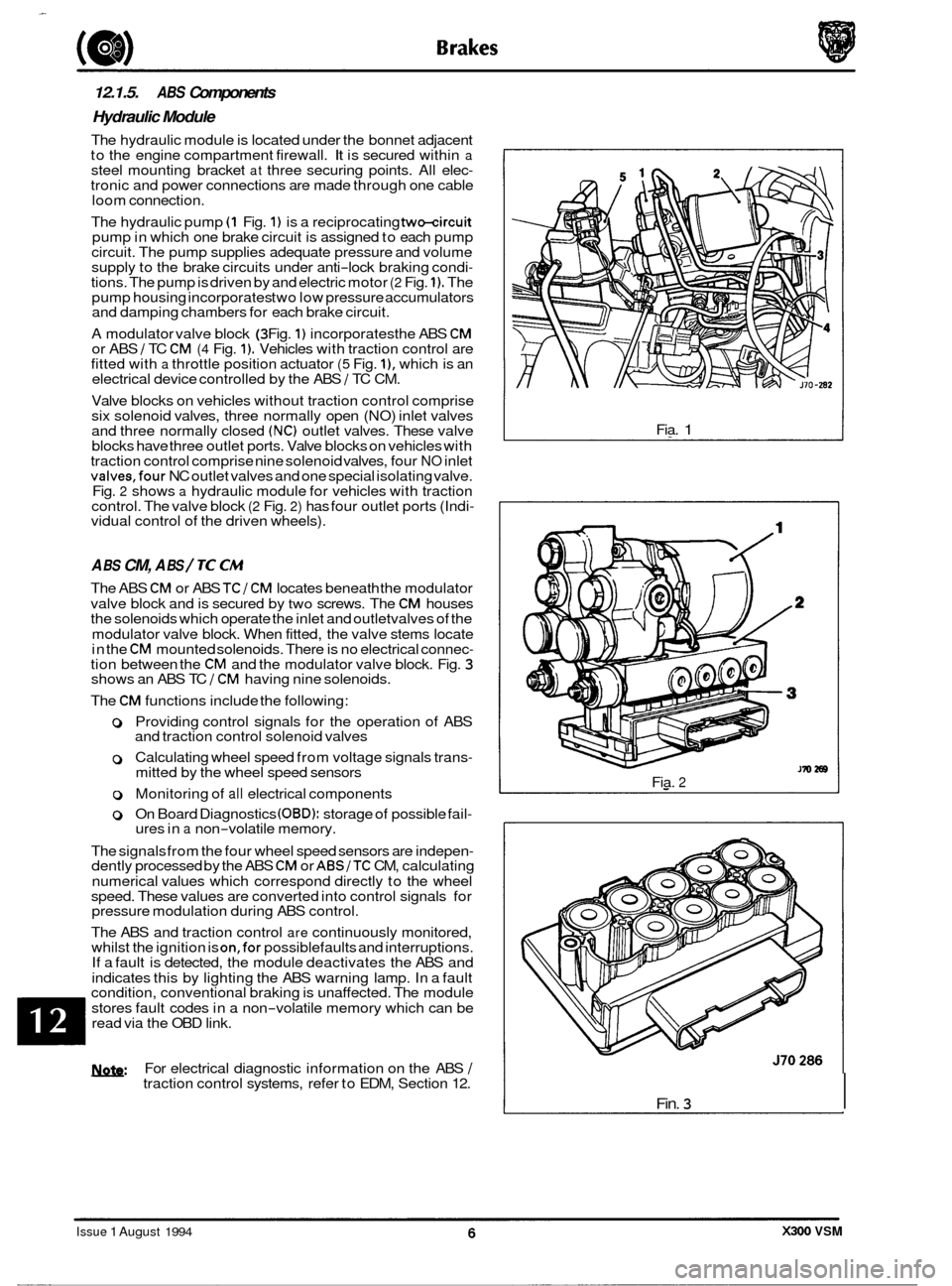
The hydraulic module is located under the bonnet adjacent
to the engine compartment firewall. It is secured within a steel mounting bracket at three securing points. All elec- tronic and power connections are made through one cable
loom connect ion.
The hydraulic pump
(1 Fig. 1) is a reciprocating two-circuit pump in which one brake circuit is assigned to each pump
circuit. The pump supplies adequate pressure and volume
supply to the brake circuits under anti
-lock braking condi- tions. The pump is driven by and electric motor (2 Fig. 1). The
pump housing incorporates two low pressure accumulators
and damping chambers for each brake circuit.
A modulator valve block
(3 Fig. 1) incorporates the ABS CM or ABS / TC CM (4 Fig. 1). Vehicles with traction control are
fitted with a throttle position actuator (5 Fig. I), which is an
electrical device controlled by the ABS 1 TC CM.
Valve blocks on vehicles without traction control comprise
six solenoid valves, three normally open (NO) inlet valves
and three normally closed
(NC) outlet valves. These valve
blocks have three outlet ports. Valve blocks on vehicles with
traction control comprise nine solenoid valves, four
NO inlet valves,four NC outlet valves and one special isolating valve.
Fig. 2 shows a hydraulic module for vehicles with traction
control. The valve block (2 Fig. 2) has four outlet ports (Indi- vidual control of the driven wheels).
A BS CM, A BS / TC CM
The ABS CM or ABS TCI CM locates beneath the modulator
valve block and is secured by
two screws. The CM houses
the solenoids which operate the inlet and outletvalves of the
modulator valve block. When fitted, the valve stems locate
in the
CM mounted solenoids. There is no electrical connec- tion between the CM and the modulator valve block. Fig. 3 shows an ABS TC 1 CM having nine solenoids.
The
CM functions include the following:
0 Providing control signals for the operation of ABS
and traction control solenoid valves
0 Calculating wheel speed from voltage signals trans- mitted by the wheel speed sensors
0 Monitoring of all electrical components
0 On Board Diagnostics (OBD): storage of possible fail- ures in a non-volatile memory.
The signals from the four wheel speed sensors are indepen
- dently processed by the ABS CM or ABSITC CM, calculating
numerical values which correspond directly to the wheel
speed. These values are converted into control signals for
pressure modulation during ABS control.
The ABS and traction control
are continuously monitored,
whilst the ignition is on,for possiblefaults and interruptions.
If a fault is detected, the module deactivates the ABS and
indicates this by lighting the ABS warning lamp. In a fault
condition, conventional braking is unaffected. The module
stores fault codes in a non
-volatile memory which can be
read via the OBD link.
U: For electrical diagnostic information on the ABS I traction control systems, refer to EDM, Section 12. Fia.
1
Fia. 2
Fin. 3 I
J70286
Issue 1 August 1994 X300 VSM
Page 234 of 521

Brakes
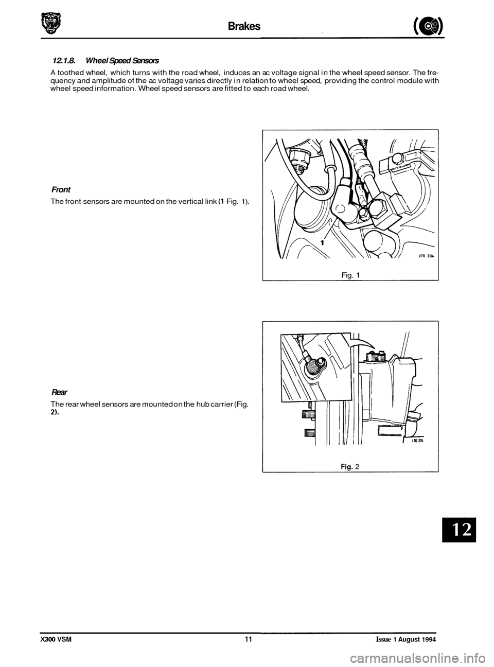
12.1.8. Wheel Speed Sensors
A toothed wheel, which turns with the road wheel, induces an ac voltage signal in the wheel speed sensor. The fre-
quency and amplitude of the ac voltage varies directly in relation to wheel speed, providing the control module with
wheel speed information. Wheel speed sensors are fitted to each road wheel.
Front
The front sensors are mounted on the vertical link (1 Fig. 1).
Fig. 1
Rear
The rear wheel sensors are mounted on the hub carrier (Fig.
2).
Fin. 2
X300 VSM 11 Issue 1 August 1994
Page 245 of 521

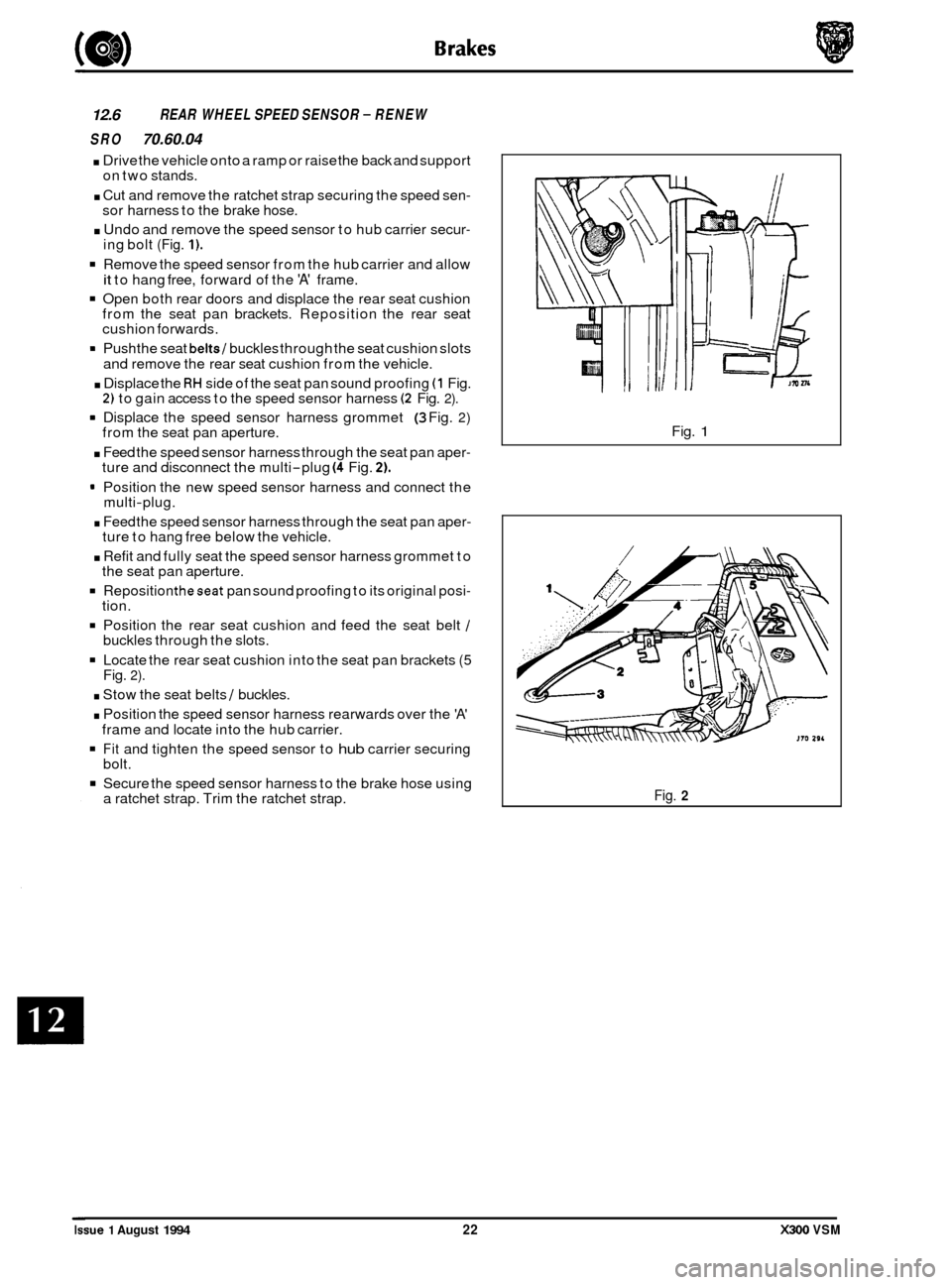
12.6 REAR WHEEL SPEED SENSOR - RENEW
SRO
70.60.04
. Drive the vehicle onto a ramp or raise the back and support
on two stands.
. Cut and remove the ratchet strap securing the speed sen- sor harness to the brake hose.
. Undo and remove the speed sensor to hub carrier secur- ing bolt (Fig. 1).
Remove the speed sensor from the hub carrier and allow
it to hang free, forward of the 'A' frame.
Open both rear doors and displace the rear seat cushion
from the seat pan brackets. Reposition the rear seat
cushion forwards.
9 Push the seat belts/ buckles through the seat cushion slots
and remove the rear seat cushion from the vehicle.
. Displace the RH side of the seat pan sound proofing (1 Fig. 2) to gain access to the speed sensor harness (2 Fig. 2).
9 Displace the speed sensor harness grommet (3 Fig. 2) from the seat pan aperture.
. Feed the speed sensor harness through the seat pan aper- ture and disconnect the multi-plug (4 Fig. 2).
9 Position the new speed sensor harness and connect the
multi-plug.
. Feed the speed sensor harness through the seat pan aper- ture to hang free below the vehicle.
. Refit and fully seat the speed sensor harness grommet to
the seat pan aperture.
Reposition theseat pan sound proofing to its original posi- tion.
Position the rear seat cushion and feed the seat belt / buckles through the slots.
Locate the rear seat cushion into the seat pan brackets (5 Fig. 2).
. Stow the seat belts / buckles.
. Position the speed sensor harness rearwards over the 'A'
Fit and tighten the speed sensor to hub carrier securing
Secure the speed sensor harness to the brake hose using
frame
and locate into the hub carrier.
bolt.
a ratchet strap. Trim the ratchet strap. Fig.
1
Fig. 2
Issue 1 August 1994 22 X300 VSM
0
0
0
Page 386 of 521

e LmmJ
Power assisted, ventilated discs,
sliding calipers: FN60 single piston
60mm Power assisted, ventilated discs,
FN48 single piston sliding calipers
48mm Mechanical, operating
on rear
drums within bell of the rear brake
discs.
291mm
305mm
28mm. wear limit 27mm
20mm, wear limit 18,5mm
Vacuum power, hydraulic operation
Bore diameter:
25,4mm
Jurid 518
Jurid 101
Ferodo 3612
6,51 vacuum
Electrical inductive sensors at the
wheels which detect rotational
speed.
Hydraulic: vehicles
with traction
control - contains four solenoid
valves, one for each wheel; vehicles
without traction control
- contains
three solenoid valves, one for each front wheel and one for both rear
wheels.
Solid state digital
unit (integral with hydraulic module).
Specification
Braking System
Front brakes: all vehicles.. ........ .................... ........... ...
Caliper piston diameter: ..........
Rear brakes: all vehicles ..........
...
...
....................
....................
...........
...........
Caliper piston diameter ...........
Parking brake ....................
...
...
....................
....................
...........
...........
Disc diameter:
Front
.........................
Rear .........................
Front .........................
Rear .........................
Brake operation .................
Master cylinder ..................
Main brake friction pad material:
Front
........................
Rear ........................
Parking brake friction shoe material
Brake
servo booster assembly
Boost ratio
......................
Disc thickness:
...
... ....................
....................
...........
...........
...
...
...
...
....................
....................
....................
....................
...........
...........
...........
...........
...
...
.. ....................
....................
....................
...........
...........
...........
... .................... ...........
Anti-lock braking system (ABSI
Wheel sensors ................... ... .................... ...........
ABS modulator .................. ... .................... ...........
0
0
Control module type ............. ... .................... .........
Issue 1 August 1994 X300 VSM AI-95MY 3