trunk release JAGUAR XJ6 1994 2.G Owner's Manual
[x] Cancel search | Manufacturer: JAGUAR, Model Year: 1994, Model line: XJ6, Model: JAGUAR XJ6 1994 2.GPages: 521, PDF Size: 17.35 MB
Page 501 of 521

Security System - RESTRICTED ISSUE 84
eb
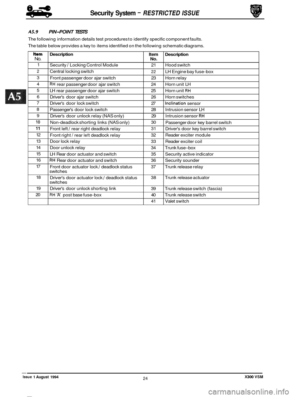
Description
Security / Locking Control Module
Central locking switch
Front passenger door ajar switch
RH rear passenger door ajar switch
LH rear passenger door ajar switch
Driver's door ajar switch
Driver's door lock switch
Passenger's door lock switch
Driver's door unlock relay (NAS only)
Non
-deadlock shorting links (NAS only)
Front left
/ rear right deadlock relay
Front right
/ rear left deadlock relay
Door lock relay
Door unlock relay
LH Rear door actuator and switch
RH Rear door actuator and switch
Front door actuator lock
/ deadlock status
switches
Driver's door actuator lock
/ deadlock status
switches
Driver's door unlock shorting link
RH 'A' post base fuse-box
A5.9 PIN-POINT TESTS
The following information details test procedures to identify specific component faults.
The table below provides a key to items identified on the following schematic diagrams.
Item Description No.
21 Hood switch
22 LH Engine bay fuse-box
23 Horn relay
24 Horn unit LH
25 Horn unit
RH
26 Horn switches
27
Inclination sensor
28 Intrusion sensor LH
29 Intrusion sensor
RH
30
31
32 Reader exciter module
33 Reader exciter coil
34 Trunk fuse
-box
35 Security active indicator
36 Security sounder
37 Trunk release relay
38 Trunk release actuator
39 Trunk release switch (fascia)
40 Trunk release switch
41 Valet switch
Passenger
door key barrel switch
Driver's door key barrel switch
Item No.
1
2
3
4
5
6
7
8
9
10
11
12
13
14
15
16
17
18
19
20
X300 VSM 24 Issue 1 August 1994
Page 515 of 521

1
Security System - RESTRICTED /SSUE
AS. 9.14 Trunk lid release switches
Check harness wiring continuity from multi-plug 12-way connector pin 2 to external trunk
release switch connector pin 10. Ensure secure ground connection from switch pin
5.
Check harness wiring continuity from multi-plug 22-way connector pin 8 to internal trunk
release switch connector pin 1. Ensure secure ground connection from switch pin
2.
Test continuity across switch pins, operate switch and ensure short circuit occurs. 3.
X300 VSM Issue 1 August 1994 38
*
J88- 1919
Fig. 1 Trunk Lid Release Switches
X300 VSM
Page 521 of 521

Security System - RESTRICTED ISSUE 84
-
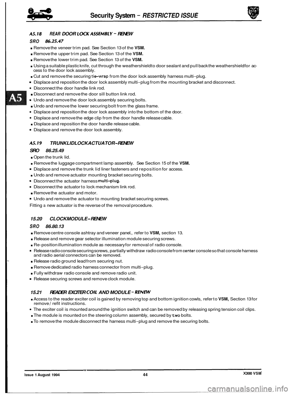
A5.18 REAR DOOR LOCKASS€MBLY - RENEW
SRO 86.25.47
. Remove the veneer trim pad. See Section 13 of the VSM.
. Remove the upper trim pad. See Section 13 of the VSM.
. Remove the lower trim pad. See Section 13 of the VSM.
. Using a suitable plastic knife, cut through the weathershield to door sealant and pull back the weathershield for ac-
. Cut and remove the securing tie-wrap from the door lock assembly harness multi-plug.
Displace and reposition the door lock assembly multi-plug from the mounting bracket and disconnect.
Disconnect the door handle link rod.
. Disconnect and remove the door sill button link rod.
= Undo and remove the door lock assembly securing bolts.
. Undo and remove the lower securing bolt from the glass frame.
Displace and reposition the door lock assembly into the bottom of the door.
Displace and remove the edge clip from the door handle release cable.
. Displace and reposition the door handle release cable.
9 Displace and remove the door lock assembly.
cess
to the door lock assembly.
A5.19 TRUNKLIDLOCKACTUATOR- RENEW
SRO 86.25.49
. Open the trunk lid.
. Remove the luggage compartment lamp assembly. See Section 15 of the VSM.
Displace and remove the trunk lid liner fasteners and reposition for access.
. Undo and remove actuator mounting bracket securing bolts.
Disconnect the actuator to lock mechanism link rod.
. Remove the actuator and motor.
Undo and remove the actuator to mounting bracket securing screws.
Fitting
a new actuator is the reverse of the removal procedure.
Disconnect
the actuator harness
multi-plug.
15.20 CLOCKMODULE- RENEW
SRO 86.80.13
. Remove centre console ashtray and veneer panel., refer to VSM, section 13.
. Release and remove gear selector illumination module securing screws.
. Re-position illumination module as necessary for removal of radio console.
= Release radio console securing screws, partially withdraw radio console from center console so that console harness
and radio aerial connectors can be removed.
. Release radio ground lead from securing nut.
. Remove dedicated radio harness connector from multi-plug.
. Fully withdraw radio console and remove radio unit.
Release securing screws and remove clock module.
15.21 READER EXCITER COIL AND MODULE - RENW
. Access to the reader exciter coil is gained by removing top and bottom ignition cowls, refer to VSM, Section 13 for
The exciter coil is mounted around the ignition switch and can be removed by releasing spring tension coil clips.
. The module is mounted on the steering column assembly, secured by two bolts.
. To remove the module disconnect the harness multi-plug and remove the securing bolts.
remove
/ refit instructions.
X300 VSM Issue 1 August 1994 44