boot JAGUAR XJ6 1994 2.G Workshop Manual
[x] Cancel search | Manufacturer: JAGUAR, Model Year: 1994, Model line: XJ6, Model: JAGUAR XJ6 1994 2.GPages: 521, PDF Size: 17.35 MB
Page 27 of 521
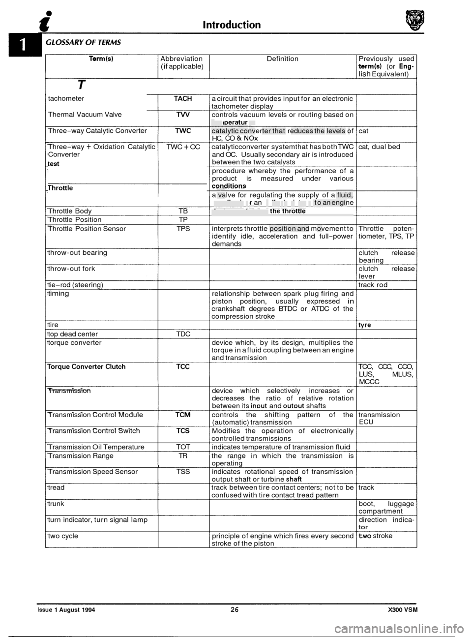
Term(s) Abbreviation Definition Previously used
(if applicable) term(s) (or Eng-
lish Equivalent)
T
tachometer
Thermal Vacuum Valve
Three
-way Catalytic Converter
Three
-way + Oxidation Catalytic
Converter TWC + OC
Throttle
------I
Throttle Body TB
Throttle Position TP
Throttle Position Sensor TPS
throw
-out bearing
throw
-out fork
tie
-rod (steering)
timing
tire
top dead center TDC
torque converter
Transmission
Transmission Control Module
Transmission Control Switch
Transmission Oil Temperature TOT
Transmission Range TR
I Transmission Speed Sensor TSS
tread
trunk
turn indicator, turn signal lamp
two cycle a
circuit that provides input for an electronic
tachometer display
controls vacuum levels or routing based on
temperature
catalytic converter that reduces the levels of
HC,
CO & NOx
catalyticconverter systemthat has both TWC
and OC. Usually secondary air is introduced
between the two catalvsts
procedure whereby the performance of a
product is measured under various
conditions - - . -. . . - . . -
a valve for regulating the supply of a fluid,
usually air or an aidfuel mixture, to an engine
device containing the throttle
interprets throttle position and movement to
identify idle, acceleration and full
-power
demands
relationship between spark plug firing and
piston position, usually expressed
in crankshaft degrees BTDC or ATDC of the
compression stroke
device which, by its design, multiplies the
torque in a fluid coupling between an engine
and transmission
device which selectively increases or
decreases the ratio of relative rotation
between its
inDut and outDut shafts
controls the shifting pattern of the
(automatic) transmission
Modifies the operation of electronically
controlled transmissions
indicates temperature
of transmission fluid
the range in which the transmission is
operating
indicates rotational speed of transmission
output shaft or turbine
shaft
track between tire contact centers; not to be
confused with tire contact tread pattern
principle of engine which fires every second
stroke of the piston cat
cat, dual bed
Throttle poten
-
tiometer, TPS, TP
clutch release
bearing
clutch release
lever
track rod
tvre
TCC, CCC, CCO,
LUS, MLUS,
MCCC
transmission
ECU
track boot, luggage
compartment
direction indica
- tor
two stroke
Issue 1 August 1994 26 X300 VSM
Page 134 of 521
Manual Transmission & Clutch (AJ16)
e
7.1.16 CLUTCH SLAVE CYLINDER, RENEW
SRO 33.35.01
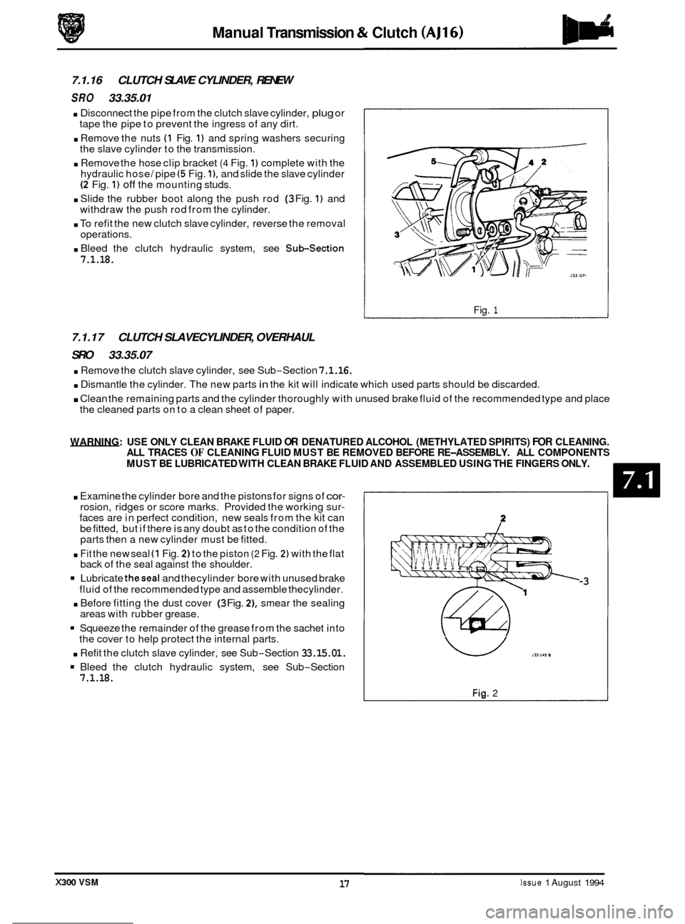
. Disconnect the pipe from the clutch slave cylinder, plug or
tape the pipe to prevent the ingress of any dirt.
. Remove the nuts (1 Fig. 1) and spring washers securing
the slave cylinder to the transmission.
. Remove the hose clip bracket (4 Fig. 1) complete with the
hydraulic hose/ pipe (5 Fig. I), and slide the slave cylinder (2 Fig. 1) off the mounting studs.
. Slide the rubber boot along the push rod (3 Fig. 1) and
withdraw the push rod from the cylinder.
. To refit the new clutch slave cylinder, reverse the removal
operations.
. Bleed the clutch hydraulic system, see Subsection
7.1.18.
Fig. 1
7.1.17 CLUTCH SLAVECYLINDER, OVERHAUL
SRO 33.35.07
. Remove the clutch slave cylinder, see Sub-Section 7.1.16.
. Dismantle the cylinder. The new parts in the kit will indicate which used parts should be discarded.
. Clean the remaining parts and the cylinder thoroughly with unused brake fluid of the recommended type and place
the cleaned parts on to a clean sheet of paper.
WARNING: USE ONLY CLEAN BRAKE FLUID OR DENATURED ALCOHOL (METHYLATED SPIRITS) FOR CLEANING.
ALL TRACES OF CLEANING FLUID MUST BE REMOVED BEFORE RE-ASSEMBLY. ALL COMPONENTS
MUST BE LUBRICATED WITH CLEAN BRAKE FLUID AND ASSEMBLED USING THE FINGERS ONLY.
. Examine the cylinder bore and the pistons for signs of cor- rosion, ridges or score marks. Provided the working sur- faces are in perfect condition, new seals from the kit can
be fitted, but if there is any doubt as to the condition of the
parts then a new cylinder must be fitted.
. Fit the new seal (1 Fig. 2) to the piston (2 Fig. 2) with the flat
back of the seal against the shoulder.
Lubricate theseal and thecylinder bore with unused brake
fluid of the recommended type and assemble thecylinder.
. Before fitting the dust cover (3 Fig. 21, smear the sealing
areas with rubber grease.
Squeeze the remainder of the grease from the sachet into
the cover to help protect the internal parts.
. Refit the clutch slave cylinder, see Sub-Section 33.15.01.
Bleed the clutch hydraulic system, see Sub-Section 7.1.18.
U 111 "I, II
Fig. 2
-3
X300 VSM 17 Issue 1 August 1994
Page 345 of 521
rl Electrical
15.1.6 Fire Hazard Infonnath
Thermal decomposition or combustion may produce dense smoke and other dangerous fumes which in fire situations
form
a highly toxic explosive.
In the event of fire the surrounding area must be evacuated and
all personnel kept well upwind of the area.
Full fire fighting protective gear and
a self contained breathing apparatus operating in the positive pressure mode must
be worn for combating fire. Material near fires must be cooled with water spray to prevent ignition.
Fires should be allowed to burn themselves
out if not threatening to life or property. If fire is threatening to life or prop- erty use copious quantities of water to extinguish.
15.1.7 Ventilath
Local exhaust ventilation designed by a professional engineer should be provided if vapours, fumes, or dusts are gen- erated whilst working with airbag module.
The latest issue of the manual for recommended practices on 'Industrial Ventilation' is available from the
ACGIH Com- mittee on Industrial Ventilation, PO Box 16153, Lansing, MI 48910, USA.
The need for local exhaust ventilation should be evaluated by a professional industrial hygienist.
15.1.8 Respiratory Precauth
To prevent the inhalation of dangerous fumes and dusts, an approved mask should be worn.
15.1.9 Eye Protection
Chemical protective goggles are recommended where there is a possibility of eye contact with the propellant.
Safety glasses with side shields are recommended for
all other operations.
15.1. I0 Protective Clothing
Approved protective gloves, overalls and shoes / boots should be worn.
15.1.1 1 Handling and Storage Precautions
Do not store airbag module near live electrical equipment or circuitry. Store in a dry environment at ambient tempera-
tures.
Good housekeeping and engineering practices should be employed to prevent the generation and accumulation of
dusts. Store in compliance with
all local state and federal regulations.
15.1.12 Driver And Passenger Airbag Modules Assembly / Removal / Service Instructions
Before starting work, ensure ignition switch is in 'IocK position, key is removed and negative terminal cable
is disconnected from the battery.
As the airbag is equipped with a back up power source and due to the risk of airbag being inadvertently
deployed, wait one minute or longer before starting work.
0 Disconnecting the battery cancels the memory for clock, radio, seats, mirrors, steering column and any other
components using battery power. Reset memory after work is completed.
0 Never use airbags from other vehicles, always use new parts.
0 After work is completed, reconnect battery and perform warning light check see diagnostic manual.
0 Never use electrical probes to check voltage or electrical resistance.
0 Disconnect the airbag before carrying out any work on, or in the vicinity of module, or when using electric weld- ing equipment.
0 Always ensure that battery negative has been disconnected for one minute or longer before commencing any
removal procedure.
EB
Issue 1 August 1994 4 X300 VSM
Page 350 of 521
31
30
29
28 27
26
4 26 24 21 23 22 7 20 19 18 18 17 8
a
10
11
12
13
14
1s
1M-137
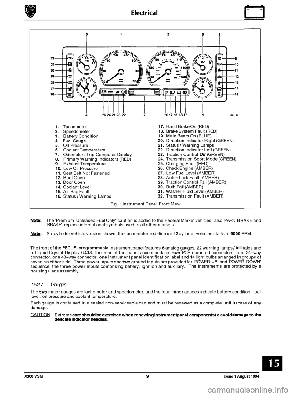
1. Tachometer 2. Speedometer
3. Battery Condition 4. FuelGauge 5. Oil Pressure 6. Coolant Temperature 7. Odometer /Trip Computer Display 8. Primary Warning Indicators (RED) 9. Exhaust Temperature 10. Low Oil Pressure 11. Seat Belt Not Fastened 12. Boot Open 13. DoorOpen 14. Coolant Level 15. Air Bag Fault 16. Status / Warning Lamps
17. Hand Brake On (RED) 18. Brake System Fault (RED)
19. Main Beam On (BLUE) 20. Direction Indicator Right (GREEN) 21. Status / Warning Lamps 22. Direction Indicator Left (GREEN) 23. Traction Control Off (GREEN) 24. Transmission Sport Mode (GREEN) 25. Charging Fault (RED) 26. Check Engine (AMBER)
27. Low Fuel Level (AMBER) 28. Anti - Lock Fault (AMBER) 29. Traction Control Fail (AMBER) 30. Bulb Fail (AMBER) 31. Washer Fluid Level (AMBER) 32. Transmission Fault (AMBER)
Fig.
1 Instrument Panel, Front Mew
w: The 'Premium Unleaded Fuel Only' caution is added to the Federal Market vehicles, also 'PARK BRAKE and
'BRAKE' replace international symbols used in all other markets.
m: Six cylinder vehicle version shown; the tachometer red-line on 12 cylinder vehicles starts at 6000 RPM.
The front of the
PECUSprogrammable instrument panel features 6 analog gauges, 22 warning lamps /tell tales and
a Liquid Crystal Display (LCD), the rear of the panel accommodates two PCB mounted connectors, one 24-way
connector, one 48-way connector, one instrument panel identification label and 14 light bulbs arranged in groups of
seven on either side. Three power inputs and two ground inputs are provided for 'POWER UP' and 'POWER DOWN'
sequence, the three power inputs comprising battery, ignition and auxiliary. The instruments are protected by a
housing
/ lens assembly.
15.2.7 Gauges
The two major gauges are tachometer and speedometer, and the four minor gauges indicate battery condition, fuel
level, oil pressure and coolant temperature.
Each gauge is contained
in a sealed non-serviceable can and must be renewed as a complete unit in case of any
damage.
CAUTION: Extreme care should be exercised when renewing instrument pand components to avoid damago to the delicate indicator needles.
X300 VSM 9 Issue 1 August 1994
Page 395 of 521
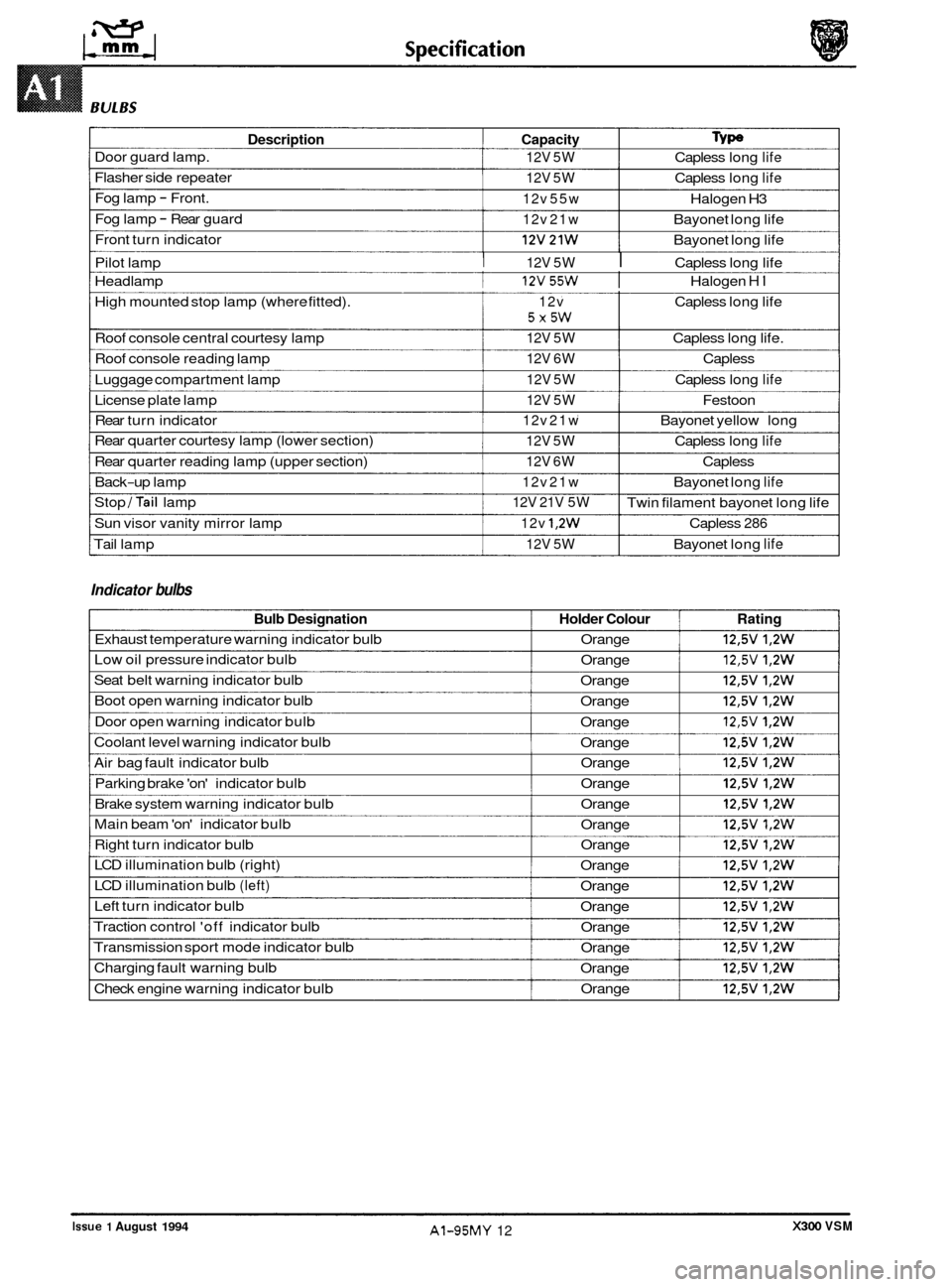
Description Capacity Type
Door guard lamp. 12V 5W Capless long life
Flasher side repeater 12V 5W Capless long life
Fog lamp - Front. 12v 55w Halogen H3
Fog lamp
- Rear guard 12v 21w Bayonet long life
Front turn indicator
I 12v21w I Bayonet long life
Pilot lamp
I 12V 5W I Capless long life
Headlamp
I 12v55w I Halogen HI
High mounted stop lamp (where fitted). 12v Capless long life
Roof console central courtesy lamp
12V 5W Capless long life.
Roof console reading lamp
12V 6W Capless
Luggage compartment lamp
12V 5W Capless long life
License plate lamp 12V 5W Festoon
Rear turn indicator
12v 21w Bayonet yellow long
Rear quarter courtesy lamp (lower section)
12V 5W Capless long life
Rear quarter reading lamp (upper section) 12V 6W Capless
Back
-up lamp 12v 21w Bayonet long life
Stop /Tail lamp
Sun visor vanity mirror lamp
12v 1,2w Capless 286
Tail lamp 12V 5W Bayonet long life
5X5W
12V 21V 5W Twin filament bayonet long life
Indicator bulbs
Bulb Designation Holder Colour Rating
Exhaust temperature warning indicator bulb Orange 12,5V 1,2W
Low oil pressure indicator bulb
Orange 12,5V 1,2W
Seat belt warning indicator bulb
Orange 12,5V 1,2W
Boot open warning indicator bulb
Orange 12,5V 1,2W
Door open warning indicator bulb
Orange 12,5V 1,2W
Coolant level warning indicator bulb
Orange 12,5V 1,2W
Air bag fault indicator bulb Orange 12,5V 1,2W
Parking brake 'on' indicator bulb Orange 12,5V 1,2W
Brake system warning indicator bulb Orange 12,5V 1,2W
Main beam 'on' indicator bulb
Orange 12,5V 1,2W
Right turn indicator bulb Orange 12,5V 1,2W
LCD illumination bulb (right)
Orange 12,5V 1,2W
LCD illumination bulb (left) Orange 12,5V 1,2W
Left turn indicator bulb
Orange 12,5V 1,2W
Traction control 'off indicator bulb
Orange 12,5V 1,2W
Transmission sport mode indicator bulb
Orange 12,5V 1,2W
Charging fault warning bulb
Orange 12,5V 1,2W
Check engine warning indicator bulb Orange 12,5V 1,2W
0
0
0
X300 VSM Issue 1 August 1994 AI-95MY 12
Page 413 of 521
General Fitting Instructions
A3.2 GENERAL FITTING INSTRUCTIONS
A3.2.1
Always fit covers to protect the wings before commencing work in the engine compartment. Cover the seats and
carpets, wear clean overalls and wash hands or wear gloves before working inside the car. Avoid spilling hydraulic
fluid, anti
-freeze or battery acid on the paintwork. In the event of spillage, wash off with water immediately. Use poly- thene sheets in the boot to protect carpets. Always use the recommended service tool, or a satisfactory equivalent,
where specified. Protect temporarily exposed screw threads by replacing nuts or fitting caps.
Precautions Against Damage To The Vehicle
A3.2.2 Preparation
Before disassembly, clean the surrounding area as thoroughly as possible. When components have been removed,
blank off any exposed openings using greaseproof paper and masking tape. Immediately seal fuel, oil and hydraulic
lines when separated, using plastic caps or plugs, to prevent loss of fluid and the entry of dirt. Close the open ends
of oilways, exposed by component removal, with tapered hardwood plugs or readily visible plastic plugs. Immediately
a component is removed, place
it in a suitable container; use a separate container for each component and its asso- ciated parts. Before dismantling a component, clean it thoroughly with a recommended cleaning agent: check that the
agent will not damage any of the materials within the component. Clean the bench and obtain marking materials, la-
bels, containers and locking wire before dismantling a component.
A3.2.3 Dismantling
Observe scrupulous cleanliness when dismantling components, particularly when parts of the brake, fuel or hydraulic
system are being worked on. A particle of dirt or a fragment of cloth could cause a dangerous malfunction if trapped in these systems. Clean all tapped holes, crevices, oilways and fluid passages with compressed air.
WRNIFLG: DO NOT PERMIT COMPRESSED AIR TO ENTER AN OPEN WOUND. ALWAYS USE EVE PROTECTION
WHEN USING COMPRESSED AIR.
Ensure that any 'O'-rings used for sealing are correctly refitted or renewed if disturbed. Mark mating parts to ensure
that they are replaced as dismantled. Whenever possible use marking materials which avoid the possibilities of caus- ing distortion or the initiation of cracks, which could occur if a center punch or scriber were used. Wire together mating
parts where necessary to prevent accidental interchange (e.g roller bearing components). Tie labels on to all parts to
be renewed and to parts requiring further inspection before being passed for reassembly.
Place labelled parts and other parts for rebuild
in separate containers.
Do not discard a part which is due for renewal until it has been compared with the new part, to ensure that the correct
part has been obtained.
A3.2.4 Inspection
Before inspecting a component for wear or performing a dimensional check, ensure that it is absolutely clean; a slight
smear of grease can conceal an incipient failure. When a component is to be checked dimensionally against figures
quoted for
it, use the correct equipment (surface plates, micrometers, dial gauges etc.) in serviceable condition. The
use of makeshift equipment can be dangerous. Reject a component if its dimensions are outside the limits quoted,
or if damage is apparent. A part may be refitted if its critical dimension is exactly to the limit size and it is otherwise
satisfactory. Use Plastigauge 12 Type PG-1 for checking bearing surface clearance e.g. big end bearing shell to crank
journal. Instructions for the use of Plastigauge and a scale giving bearing clearances in steps of
0,0025 mm (0.0001
in) are supplied with the package.
0
0
0
X300 VSM Issue 1 August 1994 2
Page 430 of 521
Systems Repair Body & Body -
A4.1.3. POTENTIAL RISKS I
A4.1.3. Paint
Organic solvents, found in paints, may cause damage or severe irritation to liver, kidneys, digestive tracts and respira- tory system if inhaled over long periods of time.
Prolonged exposure to isocyanates may cause lung sensitization. Asthma
-like symptoms may develop with subse-
quent exposure to very low concentrations of isocyanates.
Solvent inhalation can cause dizziness or loss of consciousness.
Splashes of solvents, paint activators and additives can cause damage to the eyes and may cause dermatitis. Peroxide
and acid catalysts may cause burns.
Inhalation of
spray dust and sanding debris may cause lung damage.
I
A4.1.3.2 Applied Heat (Welding)
There is considerable risk of damage to eyes and skin when welding or flame cutting.
Fire is a serious danger and many materials or fluids within the vehicle are highly flammable.
Toxic and dangerous fumes may be liberated when any of the following are subjected to heat:
0 Expanded foam
0 Corrosion protection
0 Trim and seat materials
0 Paints which contain isocyanates
0 Adhesive and sealing compounds
When heated to a temperature of 3OO0C, polyurethane based compounds may liberate small quantities of isocyanate.
Many types of nitrogen containing chemicals may be liberated as breakdown products; these chemicals can contain
isocyanates, oxides of nitrogen and hydrogen cyanide.
Potentially toxic or asphyxiant fumes and gases are produced by welding, for example; zinc oxide with zinc coated
panels, and ozone gas from the MIG process.
A4.1.3.3 Metal Repair
There is considerable risk of damage to eyes, ears and skin when metal cutting, forming, or dressing is being carried
out.
Soldering may be hazardous because of heat generated fumes and skin contact with the materials.
A4.1.4. PRECAUTIONS
A4.1.4.1 Paint
The inhalation of sprays, fumes, or dust during paint application or sanding processes should always be avoided. En- sure that there is efficient ventilation / extraction at all times. Paint spraying should be confined as far as possible to
spray booths. Personnel with a history of asthma should not be engaged in any process which involves the use of
isocyanates. Any operator working inside
a spray booth where isocyanate material is present must use air-fed breath- ing equipment. Supplied air to the visor should be fed at the recommended pressure and filtered to remove oil, water,
and fumes. Operators involved in handling mixing or spraying should wear protective clothing - gloves and goggles,
to avoid skin and eye contact.
A particle mask or canister type respirator should be worn when sanding.
A4.1.4.2 Applied Heat
When welding, flame cutting, brazing etc, the operator should use as appropriate, goggles, mask/fume extractor and
flameproof protective clothing. It is especially important when working with polyurethane compounds to use air-fed
breathing equipment.
Ensure that
at all times the appropriate fire fighting equipment is available and that personnel are trained in its use.
A4.1.4.3 Metal Repair
Appropriate eye and hand protection should be worn when sanding, drilling, cutting, chiselling, flatting or welding.
Operators should wear
a face mask or air-fed visor when sanding or flatting either body solder or fillers.
When
a soldering operation has been completed, swarf must be removed from the work area and the operator must
wash his hands thoroughly.
X300 VSM 3 Issue 1 August 1994
Page 508 of 521
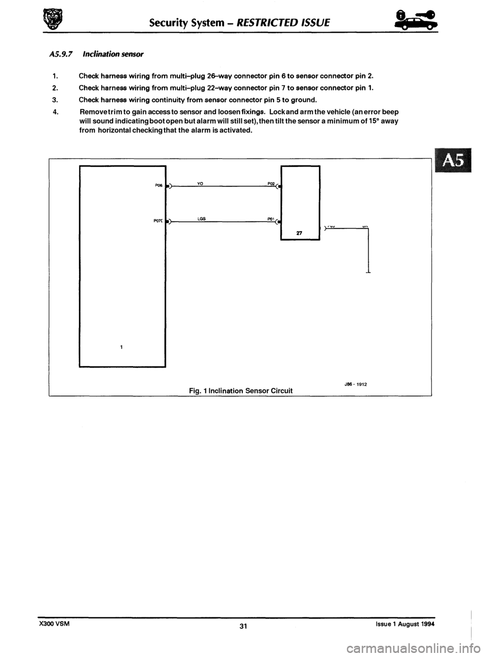
4. Remove trim to gain access to sensor and loosen fixings. Lock and arm the vehicle (an error beep
will sound indicating boot open but alarm will still set), then tilt the sensor a minimum of
15" away
from horizontal checking that the alarm is activated.
w6
Po7c
1
Fig. 1 Inclination Sensor Circuit
1
Jffi- 1912