dimensions JAGUAR XJ6 1994 2.G Workshop Manual
[x] Cancel search | Manufacturer: JAGUAR, Model Year: 1994, Model line: XJ6, Model: JAGUAR XJ6 1994 2.GPages: 521, PDF Size: 17.35 MB
Page 213 of 521
Suspension Systems
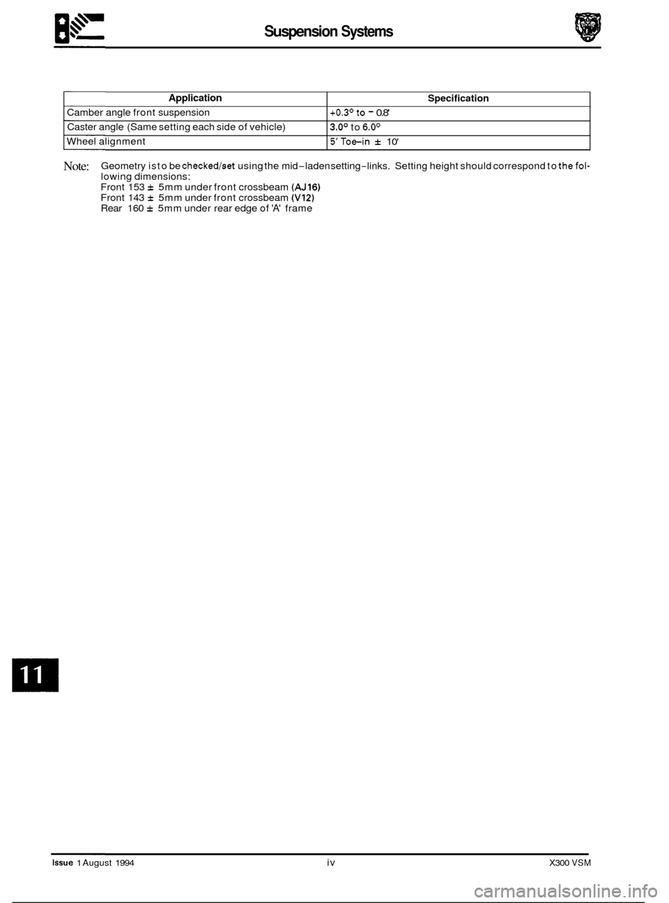
Application
Camber angle front suspension
Caster angle (Same setting each side of vehicle)
Wheel alignment
Specification
+0.3' to - 0.8'
3.0' to 6.0'
5'Toe-in f 10'
Note: Geometry is to be checked/set using the mid-laden setting-links. Setting height should correspond to thefol- lowing dimensions:
Front 153 f 5mm under front crossbeam (AJ16) Front 143 f 5mm under front crossbeam (V12) Rear 160 f 5mm under rear edge of 'A' frame
Issue 1 August 1994 iv X300 VSM
Page 387 of 521
Steering and Suspension
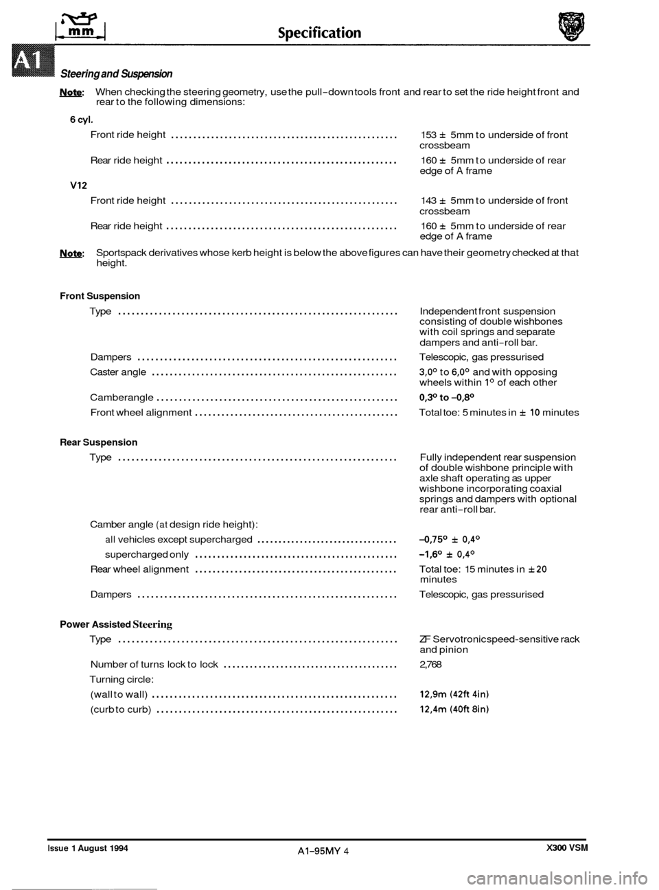
W: When checking the steering geometry, use the pull-down tools front and rear to set the ride height front and
rear to the following dimensions:
Front ride height
................................................... 153 f 5mm to underside of front
crossbeam
Rear ride height
.................................................... 160 f 5mm to underside of rear
edge of A frame
Front ride height
................................................... 143 f 5mm to underside of front
crossbeam
Rear ride height
.................................................... 160 f 5mm to underside of rear
edge of A frame
U: Sportspack derivatives whose kerb height is below the above figures can have their geometry checked at that
height.
Front Suspension
..............................................................
0
Type Independent front suspension
consisting of double wishbones
with coil springs and separate
dampers and anti
-roll bar.
Dampers
.......................................................... Telescopic, gas pressurised
Caster angle
....................................................... 3,0° to 6,0° and with opposing
wheels within Io of each other
Camberangle
...................................................... 0,3°to-0,80
Front wheel alignment .............................................. Total toe: 5 minutes in f 10 minutes
Rear Suspension
Type .............................................................. Fully independent rear suspension of double wishbone principle with
axle shaft operating as upper
wishbone incorporating coaxial
springs and dampers with optional
rear anti
-roll bar.
Camber angle
(at design ride height):
all vehicles except supercharged ................................. -0,75O f 0,4O
supercharged only -1,6O f 0,4O ..............................................
0 Rear wheel alignment .............................................. Total toe: 15 minutes in f20
Dampers .......................................................... Telescopic, gas pressurised
minutes
Power Assisted Steering
Type .............................................................. ZF
Servotronic speed-sensitive rack
and pinion
Number
of turns lock to lock ........................................ 2,768
Turning circle: (wall to wall)
....................................................... 12,9m (42ft 4in)
(curb to curb) ...................................................... 12,4m (40ft 8in)
0
X300 VSM Issue 1 August 1994 AI-95MY 4 ~~~~
Page 413 of 521
General Fitting Instructions
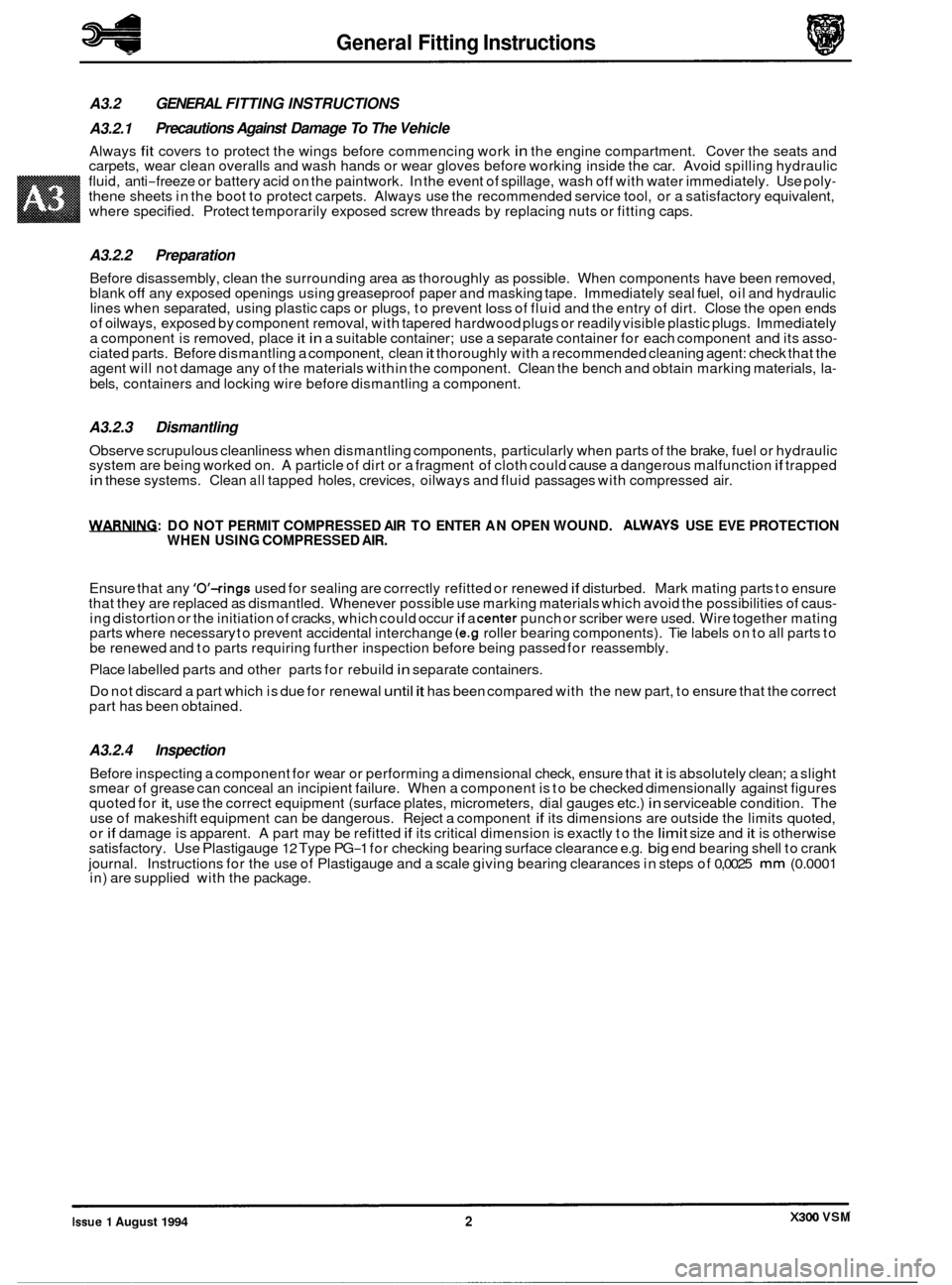
A3.2 GENERAL FITTING INSTRUCTIONS
A3.2.1
Always fit covers to protect the wings before commencing work in the engine compartment. Cover the seats and
carpets, wear clean overalls and wash hands or wear gloves before working inside the car. Avoid spilling hydraulic
fluid, anti
-freeze or battery acid on the paintwork. In the event of spillage, wash off with water immediately. Use poly- thene sheets in the boot to protect carpets. Always use the recommended service tool, or a satisfactory equivalent,
where specified. Protect temporarily exposed screw threads by replacing nuts or fitting caps.
Precautions Against Damage To The Vehicle
A3.2.2 Preparation
Before disassembly, clean the surrounding area as thoroughly as possible. When components have been removed,
blank off any exposed openings using greaseproof paper and masking tape. Immediately seal fuel, oil and hydraulic
lines when separated, using plastic caps or plugs, to prevent loss of fluid and the entry of dirt. Close the open ends
of oilways, exposed by component removal, with tapered hardwood plugs or readily visible plastic plugs. Immediately
a component is removed, place
it in a suitable container; use a separate container for each component and its asso- ciated parts. Before dismantling a component, clean it thoroughly with a recommended cleaning agent: check that the
agent will not damage any of the materials within the component. Clean the bench and obtain marking materials, la-
bels, containers and locking wire before dismantling a component.
A3.2.3 Dismantling
Observe scrupulous cleanliness when dismantling components, particularly when parts of the brake, fuel or hydraulic
system are being worked on. A particle of dirt or a fragment of cloth could cause a dangerous malfunction if trapped in these systems. Clean all tapped holes, crevices, oilways and fluid passages with compressed air.
WRNIFLG: DO NOT PERMIT COMPRESSED AIR TO ENTER AN OPEN WOUND. ALWAYS USE EVE PROTECTION
WHEN USING COMPRESSED AIR.
Ensure that any 'O'-rings used for sealing are correctly refitted or renewed if disturbed. Mark mating parts to ensure
that they are replaced as dismantled. Whenever possible use marking materials which avoid the possibilities of caus- ing distortion or the initiation of cracks, which could occur if a center punch or scriber were used. Wire together mating
parts where necessary to prevent accidental interchange (e.g roller bearing components). Tie labels on to all parts to
be renewed and to parts requiring further inspection before being passed for reassembly.
Place labelled parts and other parts for rebuild
in separate containers.
Do not discard a part which is due for renewal until it has been compared with the new part, to ensure that the correct
part has been obtained.
A3.2.4 Inspection
Before inspecting a component for wear or performing a dimensional check, ensure that it is absolutely clean; a slight
smear of grease can conceal an incipient failure. When a component is to be checked dimensionally against figures
quoted for
it, use the correct equipment (surface plates, micrometers, dial gauges etc.) in serviceable condition. The
use of makeshift equipment can be dangerous. Reject a component if its dimensions are outside the limits quoted,
or if damage is apparent. A part may be refitted if its critical dimension is exactly to the limit size and it is otherwise
satisfactory. Use Plastigauge 12 Type PG-1 for checking bearing surface clearance e.g. big end bearing shell to crank
journal. Instructions for the use of Plastigauge and a scale giving bearing clearances in steps of
0,0025 mm (0.0001
in) are supplied with the package.
0
0
0
X300 VSM Issue 1 August 1994 2
Page 436 of 521
Body Systems
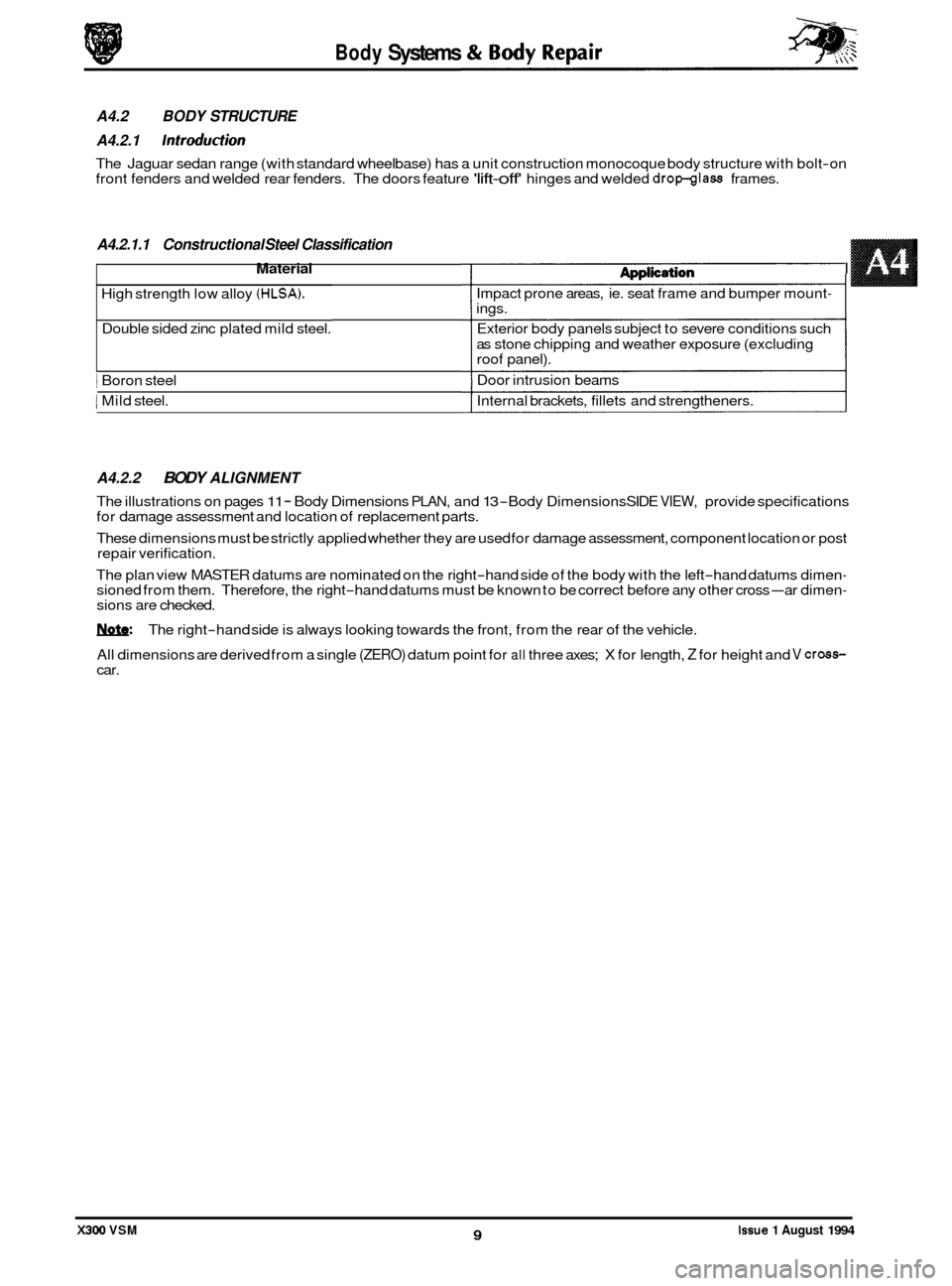
A4.2.1.1 Constructional Steel Classification
Material 1 dnnlirdiam I
High strength low alloy (HLSA).
Double sided zinc plated mild steel.
1 Boron steel
1 Mild steel.
A4.2.2 BODY ALIGNMENT
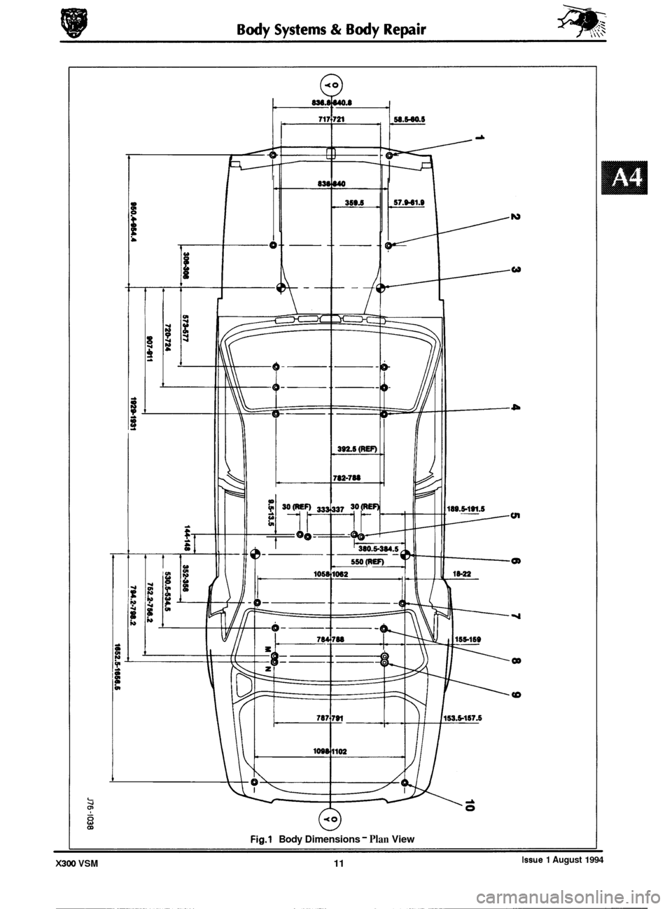
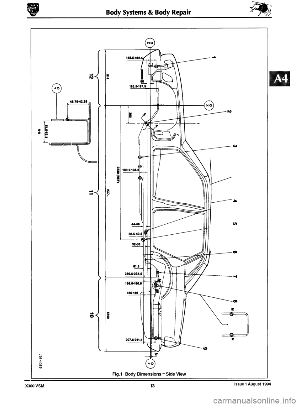
The illustrations on pages 11 - Body Dimensions PLAN, and 13 -Body Dimensions SIDE VIEW, provide specifications
for damage assessment and location of replacement parts.
These dimensions must be strictly applied whether they are used for damage assessment, component location or post
repair verification.
The plan view MASTER datums are nominated on the right
-hand side of the body with the left-hand datums dimen- sioned from them. Therefore, the right-hand datums must be known to be correct before any other cross-ar dimen- sions are checked.
W: The right-hand side is always looking towards the front, from the rear of the vehicle.
All dimensions are derived from a single
(ZERO) datum point for all three axes; X for length, Z for height and V cross- car.
Issue 1 August 1994 9 X300 VSM
A4.2 BODY STRUCTURE
A4.2.1
Introduction
The Jaguar sedan range (with standard wheelbase) has a unit construction monocoque body structure with bolt-on
front fenders and welded rear fenders. The doors feature 'lift-off' hinges and welded dropglass frames.
n@#pn.s..v..
Impact prone areas, ie. seat frame and bumper mount- ings.
Exterior body panels subject to severe conditions such
as stone chipping and weather exposure (excluding
roof panel).
Door intrusion beams
Internal brackets, fillets and strengtheners.
I
Page 438 of 521
0
0
0
-
0
w
tn
Q)
OD
Fig.1 Body Dimensions - Plan View
Issue 1 August 1994 X300 VSM 11
Page 440 of 521
0
0
0
-
0
v 3
I so 185.5-187.!
t
4
230.5-234.5
i:: cn
I m
8
Fig.1 Body Dimensions - Side View
Issue 1 August 1994 X300 VSM 13
Page 461 of 521
Body Systems & Body Repair
Optimum temperature 6OoC - 7OoC
Minimum temperature 35%
Maximum Temperature 7 5oc
A4.5 GLAZING
A4.5.1 Special notes
In order that the design condition of the vehicle is preserved when direct glazing repairs are carried out, it is essential
that both the applied materials and processes are as stipulated.
Application time - including
positioning
4 minutes
Will not bond
A4.5.1.1 Glass and Body Preparation
The preparation methods and materials, as used with the Betaseal HV3 system on previous Jaguar vehicles, are fully
compatible with the current sedan range.
Ease of working and extended process time may be gained by ensuring that the vehicle body and replacement glass
are 'soaked
at room temperature, a minimum of 2OoC, prior to adhesive application and fitting.
Should damage occur to the body flange finish, rectify as appropriate with the full paint refinishing process as de
- scribed in the 'Paint Refinishing Manual' see section 4.4.1.1.
A4.5.1.2 Adhesive Application Temperature
The specified adhesive has a high viscosity and is not easily applied at 'room temperature' using conventional
methods. When the adhesive is applied it chills rapidly on contact with the body and reverts to the hard condition, thus
providing full retention (not full strength) within minutes.
Raising the temperature of the adhesive lowers the viscosity and speeds up the flow.
It is recommended therefore that
the adhesive is pre-warmed in a heated cabinet for a minimum of 20 (twenty) minutes and the extrusion gun has inte- gral heating elements, see Preliminary pages for details.
A4.5.1.3 Adhesive Application
CAUTION: The glass will not bond to the body if the time
taken to apply the adhesive AND position the glass. exceeds the stated limit.
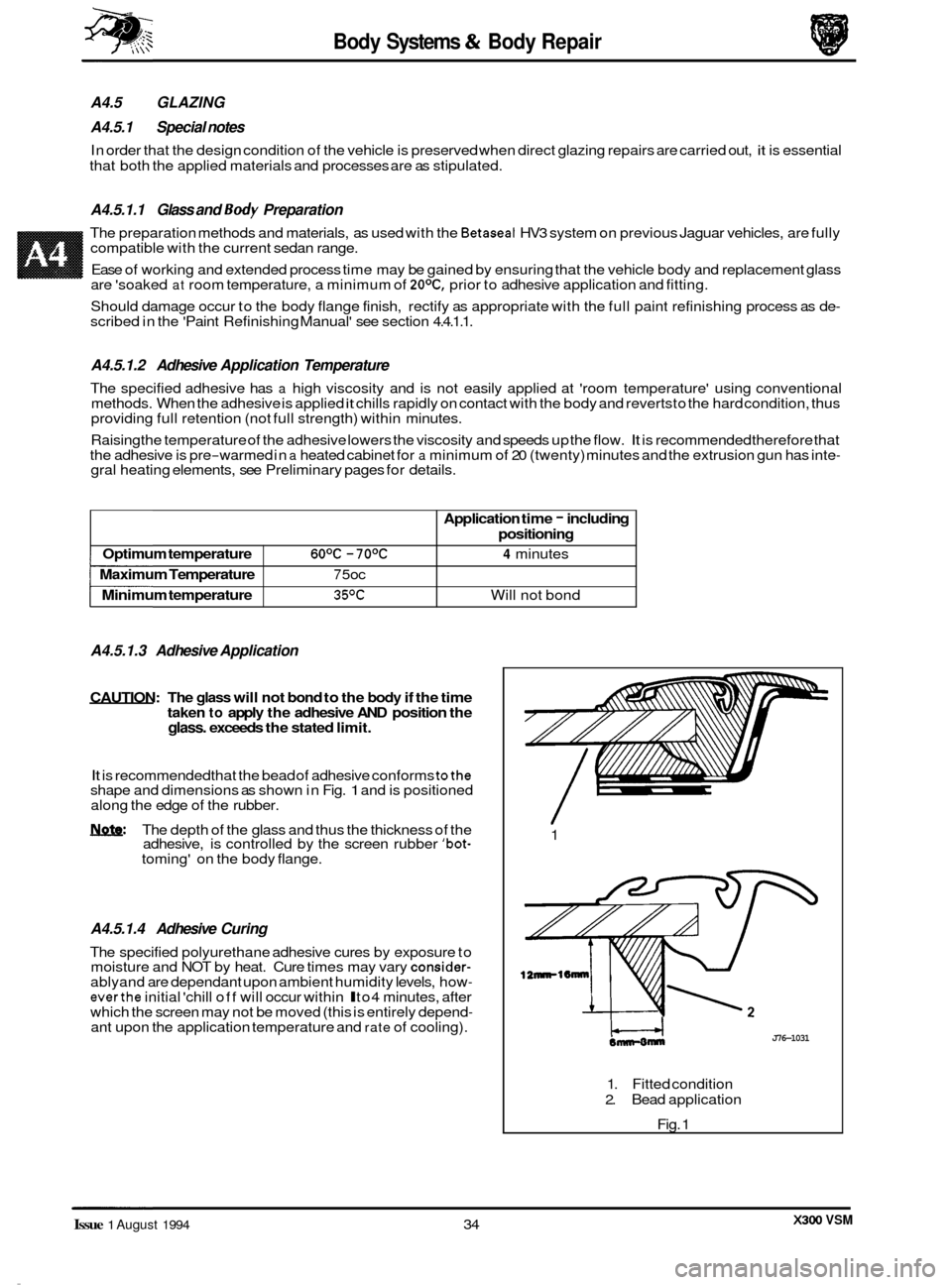
It is recommended that the bead of adhesive conforms tothe shape and dimensions as shown in Fig. 1 and is positioned
along the edge of the rubber.
m: The depth of the glass and thus the thickness of the
adhesive, is controlled by the screen rubber 'bot- toming' on the body flange.
A4.5.1.4 Adhesive Curing
The specified polyurethane adhesive cures by exposure to
moisture and NOT by heat. Cure times may vary consider- ablyand are dependant upon ambient humidity levels, how- everthe initial 'chill off will occur within l to4 minutes, after
which the screen may not be moved (this is entirely depend- ant upon the application temperature and rate of cooling). 1
12nnrl6mnr
J76-1031
1.
Fitted condition
2. Bead application
Fig. 1
X300 VSM Issue 1 August 1994 34
Page 464 of 521
conditions.
. Tighten all fixings to specification.
A4.6.1.3 SERVICE PROCEDURES
A4.6.1.4
Fitted Condition (Front)
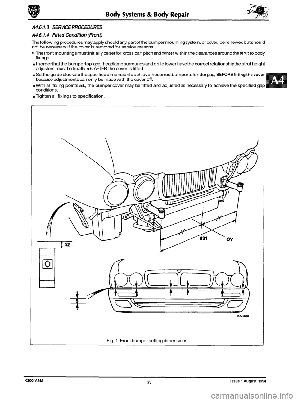
The following procedures may apply should any part of the bumper mounting system, or cover, be renewed but should
not be necessary if the cover is removed for service reasons.
The front mountings must initially be set for 'cross car' pitch and center within the clearances around thestrut to body
. In orderthat the bumpertop face, headlamp surrounds and grille lower have the correct relationship the strut height
. Set the guide blocksto thespecified dimensionto achievethecorrect bumpertofender gap, BEFOREfittingthecover
. With all fixing points set, the bumper cover may be fitted and adjusted as necessary to achieve the specified gap
fixings.
adjusters must be finally
set AFTER the cover is fitted.
because adjustments can only be made with the cover
off.
Fig. 1 Front bumper setting dimensions
Issue 1 August 1994 37 X300 VSM
Page 465 of 521
Body Systems & Body Repair
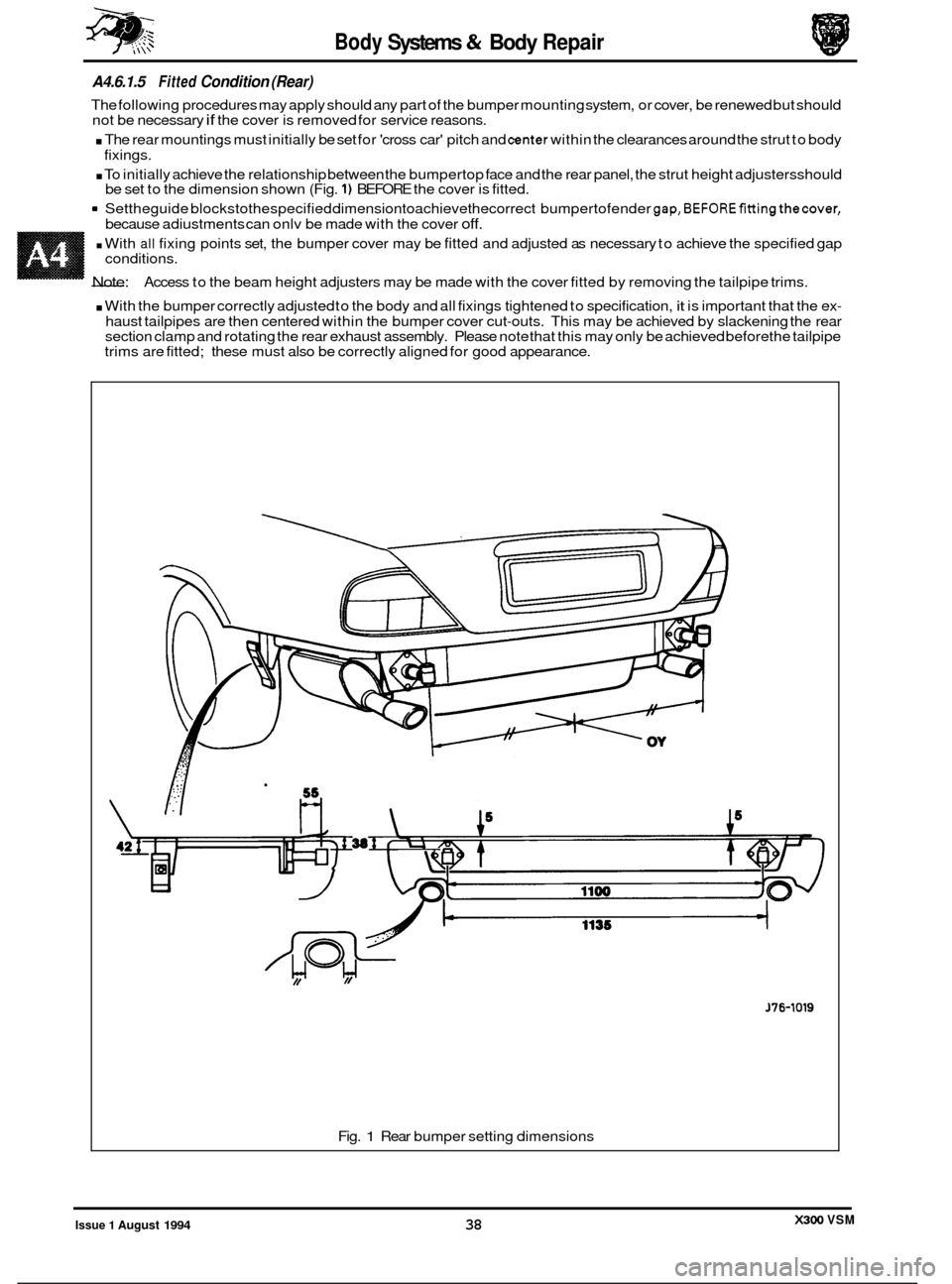
A4.6.1.5 Fitted Condition (Rear)
The following procedures may apply should any part of the bumper mounting system, or cover, be renewed but should
not be necessary if the cover is removed for service reasons.
. The rear mountings must initially be set for 'cross car' pitch and center within the clearances around the strut to body
. To initially achieve the relationship between the bumpertop face and the rear panel, the strut height adjustersshould
9 Settheguide blockstothespecified dimensiontoachievethecorrect bumpertofender gap,BEFOREfittingthecover,
fixings.
be set to the dimension shown (Fig.
1) BEFORE the cover is fitted.
because adiustments can onlv be made with the cover
off.
. With all fixing points set, the bumper cover may be fitted and adjusted as necessary to achieve the specified gap
- Note:
conditions.
Access to the beam height adjusters may be made with the cover fitted by removing the tailpipe trims.
. With the bumper correctly adjusted to the body and all fixings tightened to specification, it is important that the ex-
haust tailpipes are then centered within the bumper cover cut-outs. This may be achieved by slackening the rear
section clamp and rotating the rear exhaust assembly. Please note that this may only be achieved before the tailpipe
trims are fitted; these must also be correctly aligned for good appearance.
J76-1019
Fig. 1 Rear bumper setting dimensions
X300 VSM Issue 1 August 1994 38