torque JAGUAR XJ6 1994 2.G Workshop Manual
[x] Cancel search | Manufacturer: JAGUAR, Model Year: 1994, Model line: XJ6, Model: JAGUAR XJ6 1994 2.GPages: 521, PDF Size: 17.35 MB
Page 3 of 521
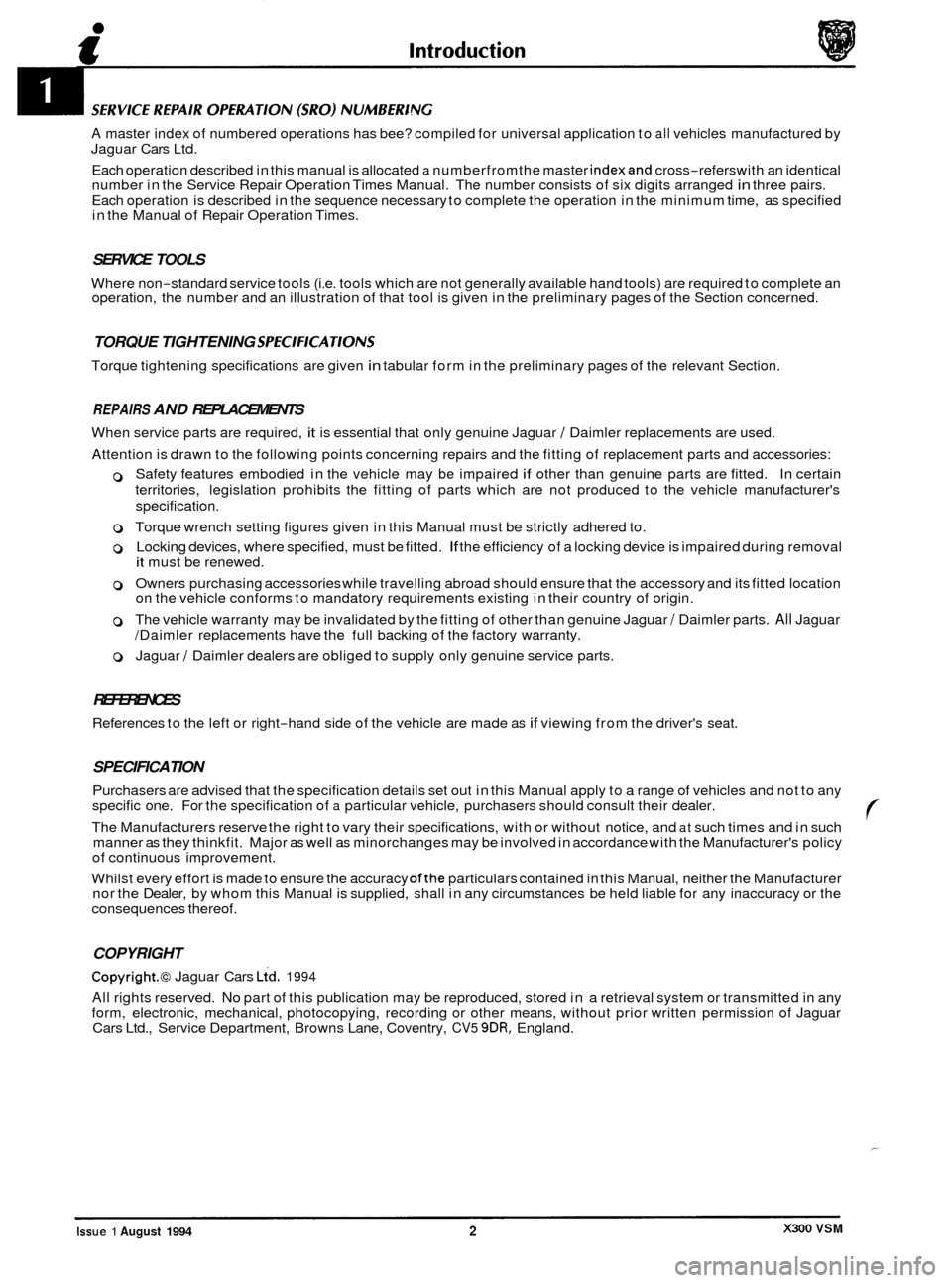
A master index of numbered operations has bee? compiled for universal application to all vehicles manufactured by
Jaguar Cars Ltd.
Each operation described in this manual is allocated
a numberfromthe master indexand cross-refers with an identical
number in the Service Repair Operation Times Manual. The number consists of six digits arranged in three pairs.
Each operation is described in the sequence necessary to complete the operation in the minimum time, as specified
in the Manual of Repair Operation Times.
SERVICE TOOLS
Where non-standard service tools (i.e. tools which are not generally available hand tools) are required to complete an
operation, the number and an illustration of that tool is given in the preliminary pages of the Section concerned.
TORQUE TIGHTENING SPEClFKATlONS
Torque tightening specifications are given in tabular form in the preliminary pages of the relevant Section.
REPAIRS AND REPLACEMENTS
When service parts are required, it is essential that only genuine Jaguar / Daimler replacements are used.
Attention is drawn to the following points concerning repairs and the fitting of replacement parts and accessories:
0 Safety features embodied in the vehicle may be impaired if other than genuine parts are fitted. In certain
territories, legislation prohibits the fitting of parts which are not produced to the vehicle manufacturer's
specification.
0 Torque wrench setting figures given in this Manual must be strictly adhered to.
0 Locking devices, where specified, must be fitted. If the efficiency of a locking device is impaired during removal it must be renewed.
0 Owners purchasing accessories while travelling abroad should ensure that the accessory and its fitted location
on the vehicle conforms to mandatory requirements existing in their country of origin.
0 The vehicle warranty may be invalidated by the fitting of other than genuine Jaguar / Daimler parts. All Jaguar
/Daimler replacements have the full backing of the factory warranty.
0 Jaguar / Daimler dealers are obliged to supply only genuine service parts.
REFERENCES
References to the left or right-hand side of the vehicle are made as if viewing from the driver's seat.
SPECIFICATION
Purchasers are advised that the specification details set out in this Manual apply to a range of vehicles and not to any
specific one. For the specification of a particular vehicle, purchasers should consult their dealer.
The Manufacturers reserve the right to vary their specifications, with or without notice, and
at such times and in such
manner as they thinkfit. Major as well as minorchanges may be involved in accordance with the Manufacturer's policy
of continuous improvement.
Whilst every effort is made to ensure the accuracy
ofthe particulars contained in this Manual, neither the Manufacturer
nor the Dealer, by whom this Manual is supplied, shall in any circumstances be held liable for any inaccuracy or the
consequences thereof.
COPYRIGHT
Copyright.@ Jaguar Cars Lid. 1994
All rights reserved. No part of this publication may be reproduced, stored in a retrieval system or transmitted in any
form, electronic, mechanical, photocopying, recording or other means, without prior written permission of Jaguar
Cars Ltd., Service Department, Browns Lane, Coventry,
CV5 9DR, England.
X300 VSM Issue 1 August 1994 2
Page 21 of 521
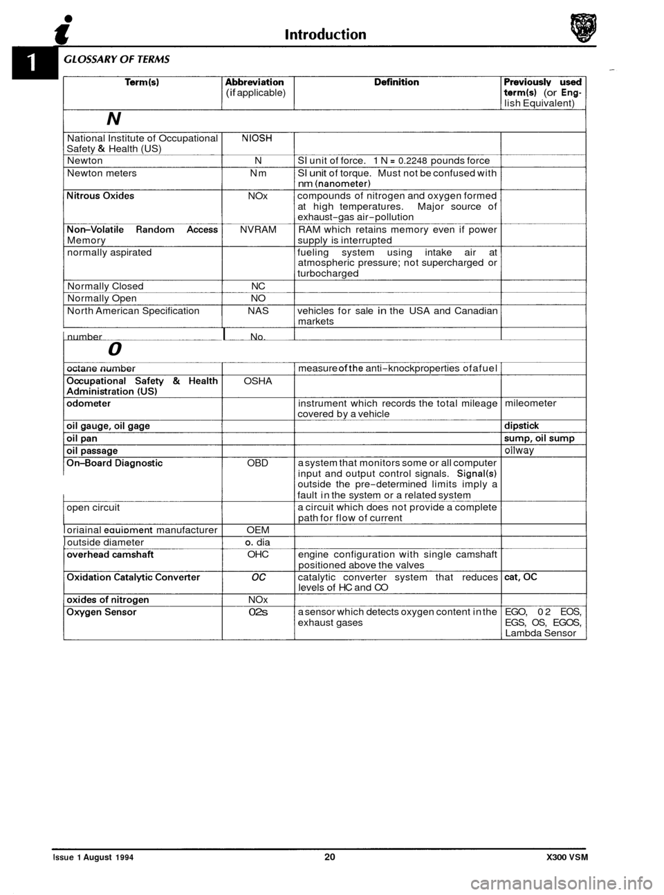
(if applicable) term(s) (or Eng- lish Equivalent)
N
National Institute of Occupational NIOSH Safety & Health (US)
Newton N SI unit of force. 1 N = 0.2248 pounds force
Newton meters Nm
SI unit of torque. Must not be confused with nm (nanometer)
compounds of nitrogen and oxygen formed
at high temperatures. Major source of
exhaust
-gas air-pollution
RAM which retains memory even if power
N
Ox
NVRAM
Memory supply is interrupted
normally aspirated fueling system using intake air at
atmospheric pressure; not supercharged or
turbocharged
Normally Closed NC
Normally Open NO
North American Specification NAS vehicles for sale
in the USA and Canadian
markets
0
I number I No.
octane number
I
I open circuit
I oriainal eauiDment manufacturer
I outside diameter OSHA
OBD
OEM
0. dia
OHC
oc
N Ox
02s
measure ofthe anti-knockproperties ofafuel
instrument which records the total mileage
covered by a vehicle
a system that monitors some or all computer
input and output control signals.
Signal(s) outside the pre-determined limits imply a
fault in the svstem or a related svstem
a circuit which does not provide a complete
path for flow of current
engine configuration with single camshaft
positioned above the valves
catalytic converter system that reduces
levels
of HC and CO
a sensor which detects oxygen content in the
exhaust gases mileometer
oilwav
EGO,
02 EOS,
EGS, OS, EGOS,
Lambda Sensor
Issue 1 August 1994 20 X300 VSM
Page 27 of 521
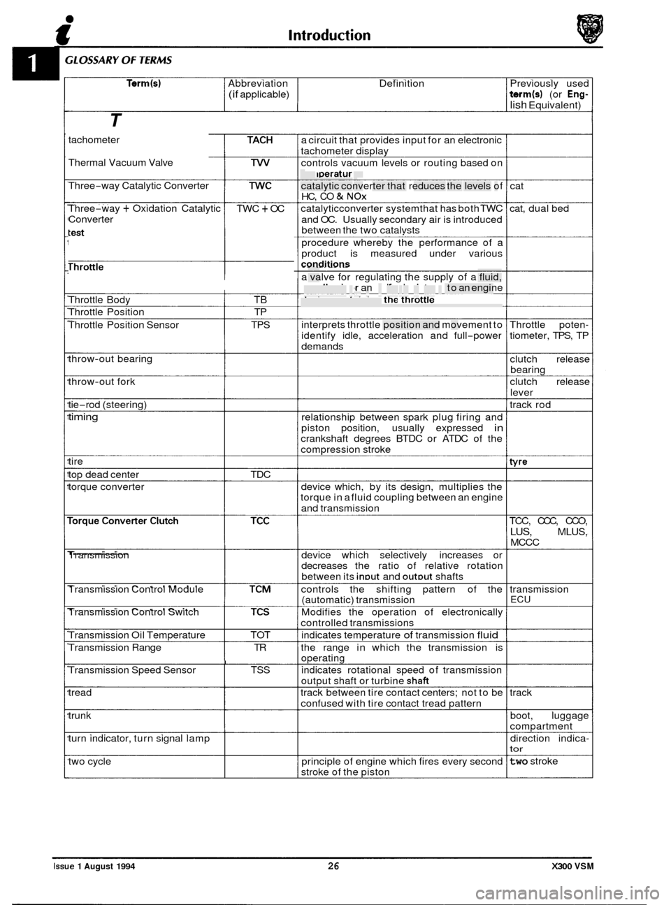
Term(s) Abbreviation Definition Previously used
(if applicable) term(s) (or Eng-
lish Equivalent)
T
tachometer
Thermal Vacuum Valve
Three
-way Catalytic Converter
Three
-way + Oxidation Catalytic
Converter TWC + OC
Throttle
------I
Throttle Body TB
Throttle Position TP
Throttle Position Sensor TPS
throw
-out bearing
throw
-out fork
tie
-rod (steering)
timing
tire
top dead center TDC
torque converter
Transmission
Transmission Control Module
Transmission Control Switch
Transmission Oil Temperature TOT
Transmission Range TR
I Transmission Speed Sensor TSS
tread
trunk
turn indicator, turn signal lamp
two cycle a
circuit that provides input for an electronic
tachometer display
controls vacuum levels or routing based on
temperature
catalytic converter that reduces the levels of
HC,
CO & NOx
catalyticconverter systemthat has both TWC
and OC. Usually secondary air is introduced
between the two catalvsts
procedure whereby the performance of a
product is measured under various
conditions - - . -. . . - . . -
a valve for regulating the supply of a fluid,
usually air or an aidfuel mixture, to an engine
device containing the throttle
interprets throttle position and movement to
identify idle, acceleration and full
-power
demands
relationship between spark plug firing and
piston position, usually expressed
in crankshaft degrees BTDC or ATDC of the
compression stroke
device which, by its design, multiplies the
torque in a fluid coupling between an engine
and transmission
device which selectively increases or
decreases the ratio of relative rotation
between its
inDut and outDut shafts
controls the shifting pattern of the
(automatic) transmission
Modifies the operation of electronically
controlled transmissions
indicates temperature
of transmission fluid
the range in which the transmission is
operating
indicates rotational speed of transmission
output shaft or turbine
shaft
track between tire contact centers; not to be
confused with tire contact tread pattern
principle of engine which fires every second
stroke of the piston cat
cat, dual bed
Throttle poten
-
tiometer, TPS, TP
clutch release
bearing
clutch release
lever
track rod
tvre
TCC, CCC, CCO,
LUS, MLUS,
MCCC
transmission
ECU
track boot, luggage
compartment
direction indica
- tor
two stroke
Issue 1 August 1994 26 X300 VSM
Page 39 of 521
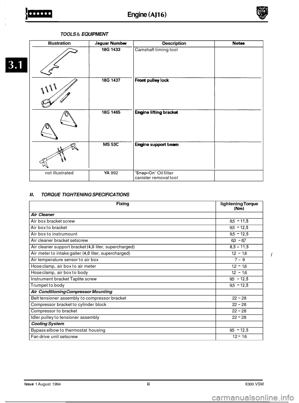
Engine (AJ16)
Description
Camshaft timing tool
TOOLS & EQUIPMENT
Not- Illustration I JaguarNumber
L L
11. TORQUE TIGHTENING SPECIFICATIONS
not illustrated YA 992
Fixing
Air Cleaner
Air box bracket screw
Air box to bracket
Air box to instrumount
Air cleaner bracket setscrew
Air cleaner support bracket
(4,O liter, supercharged)
Air meter to intake gaiter
(4,O liter, supercharged)
Air temperature sensor to air box
Hose clamp, air box to air meter
Hose clamp, air box to body
Instrument bracket Taptite screw
Trumpet to body
Air Conditioning Compressor Mounting
Belt tensioner assembly to compressor bracket
Compressor bracket to cylinder block
Compressor to bracket
Idler pulley to tensioner assembly
Cooling System
Bypass elbow to thermostat housing
Fan drive unit setscrew
lightening Torque
(Nm)
8,5 - 11,5
9,5 - 12,5
9,5 - 12,5
6,3 - 8,7
8,5- 11,5
1,2 - 1,6
7
-9
1.2
- 1,6
1,2
- 1,6
9,5
- 12,5
9,5 - 12,5
22 - 28
22
- 28
22
- 28
22
- 28
9.5
- 12,5
12 - 16
Front pulley lock
fi
Engine lifting bracket
fi
Engine support beam
fl
'Snap-On' Oil filter
canister removal tool
Issue 1 August 1994 ii X300 VSM
Page 40 of 521
Engine (AJ16) 1-
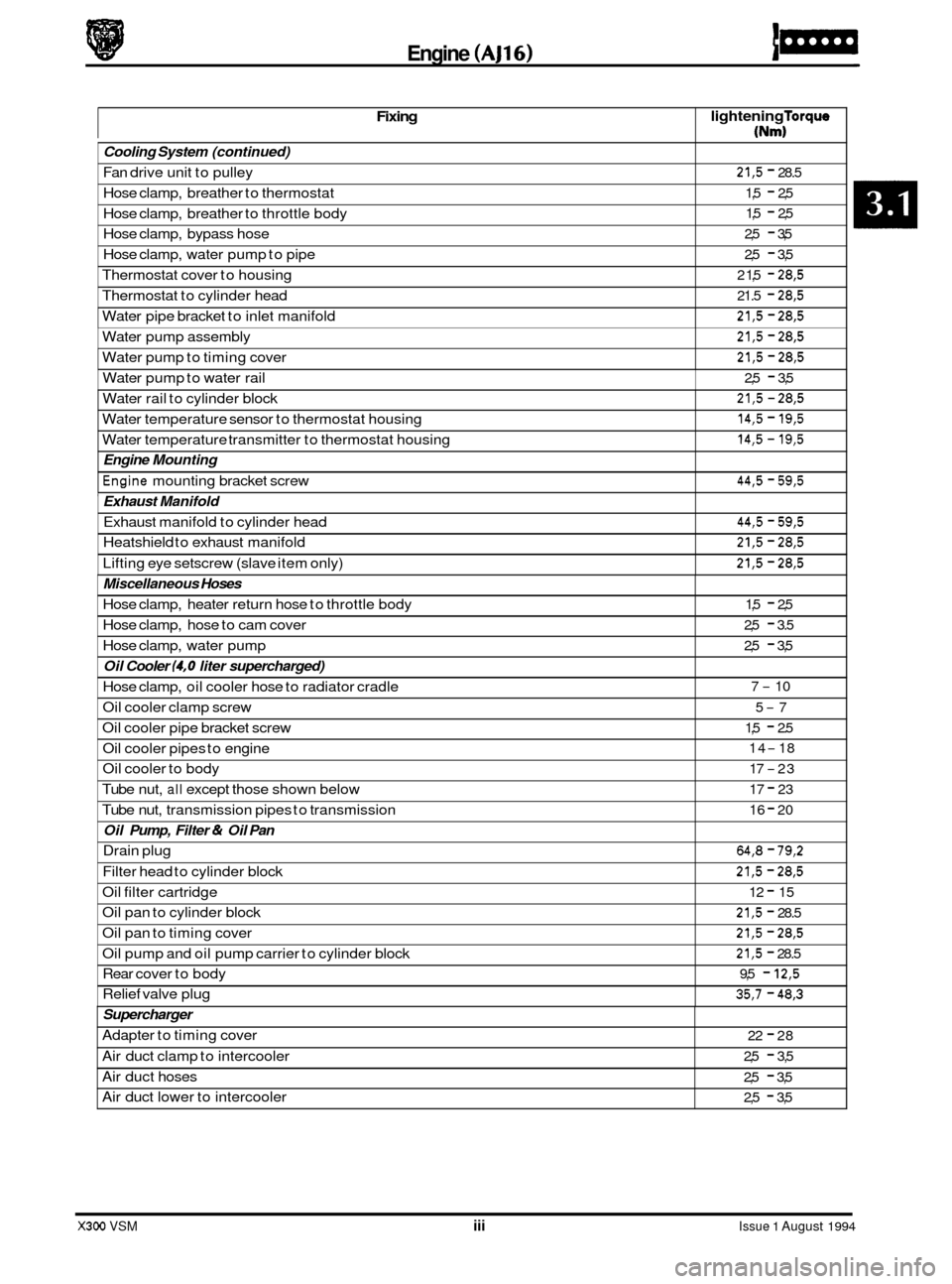
Fixing lightening Torque
(Nm)
Cooling System
(continued)
Fan drive unit to pulley
Hose clamp, breather to thermostat
Hose clamp, breather to throttle body
Hose clamp, bypass hose
Hose clamp, water pump to pipe
Thermostat cover to housing
Thermostat to cylinder head
Water pipe bracket to inlet manifold 21,5 - 28.5
1,5
- 2,5
1,5
- 2,5
2,5
- 3,5
2,5
- 3,5
2 1,5
- 28,5
21.5 - 28,5
21,5 - 28,5
Water pump assembly
Water pump to timing cover 21,5 - 28,5
21,5 - 28,5
Water pump to water rail 2,5 - 3,5
Water rail to cylinder block
X300 VSM iii Issue 1 August 1994
21,5 - 28,5
@
Water temperature sensor to thermostat housing
Water temperature transmitter to thermostat housing 14,5 - 19,5
14,5 - 19,5
44,5 - 59,5
Engine Mounting
*Engine mounting bracket screw
' Exhaust Manifold
Exhaust manifold to cylinder head
Heatshield to exhaust manifold
Lifting eye setscrew (slave item only) 44,5 - 59,5
21,5 - 28,5
21,5 - 28,5
Miscellaneous Hoses
Hose clamp, heater return hose to throttle body
Hose clamp, hose to cam cover
Hose clamp, water pump
Oil Cooler (4,O liter supercharged)
Hose clamp, oil cooler hose to radiator cradle
Oil cooler clamp screw
5-7
Oil cooler pipe bracket screw
Oil cooler pipes to engine
Oil cooler to body
Tube nut,
all except those shown below
Tube nut, transmission pipes to transmission
1,5 - 2,5
2,5
- 3.5
2,5
- 3,5
7
- 10
1,5
- 2.5
14
- 18
17
-23
17
- 23
16
- 20
Oil Pump, Filter & Oil Pan
Drain plug 64,8 - 79,2
Filter head to cylinder block 21,5 - 28,5
Oil filter cartridge 12 - 15
Oil pan to cylinder block 21,5 - 28.5
Oil pan to timing cover 21,5 - 28,5
Oil pump and oil pump carrier to cylinder block 21,5 - 28.5
Rear cover to body 9,5 - 12,5
Relief valve plug 35,7 - 48,3
Supercharger
Adapter to timing cover
Air duct clamp to intercooler
Air duct hoses
Air duct lower to intercooler 22 - 28
2,5
- 3,5
2,5
- 3,5
2,5
- 3,5
Page 41 of 521
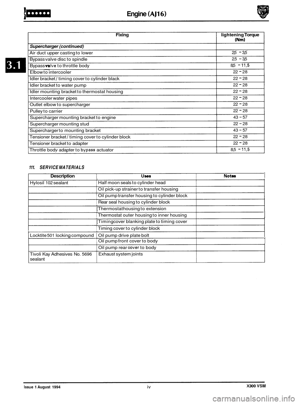
Idler bracket / timing cover to cylinder black
Idler bracket to water pump
Idler mounting bracket to thermostat housing
lntercooler water pipes
Outlet elbow to supercharger
Pulley to carrier 22 - 28
22
- 28
22
- 28
22
- 28
22
- 28
22
- 28
43
- 57
22
- 28
43
- 57
22
- 28
22
- 28
8,5
- 11,5
Supercharger mounting bracket to engine
Supercharger to mounting bracket
Supercharger
mounting stud
Tensioner bracket
/ timing cover to cylinder block
Tensioner bracket to adapter
Throttle bodv adapter to
bypass actuator
Engine (AJ16)
Fixing lightening Torque
Supercharger (continued)
Air duct upper casting to lower
Bypass valve disc to spindle
Bypass
mlve to throttle body
Elbow to intercooler
2,5 - 3,5
2.5
- 3,5
8,5
- 11,5
22 - 28 ~~ ~
111.
SERVICE MATERIALS
Description USOS Notea 1 I I Hylosil 102 sealant 1 Half moon seals to cylinder head I I Oil pick-up strainer to transfer housing I 1 Oil pump transfer housing to cylinder block 1
[ Rear seal housing to cylinder block , [Thermostat housing to extension , I Thermostat outer housing to inner housing 1 , [Timing cover blanking plate to timing cover 1 I I Timing cover to cylinder block
I Locktite 501 locking compound I Oil pump drive plate bolt
,
,
I Oil pump front cover to body 1
I Oil pump rear cover to body
I Exhaust system joints
Tivoli Kay Adhesives No. 5696
sealant
X300 VSM Issue 1 August 1994 iv
Page 44 of 521
Engine
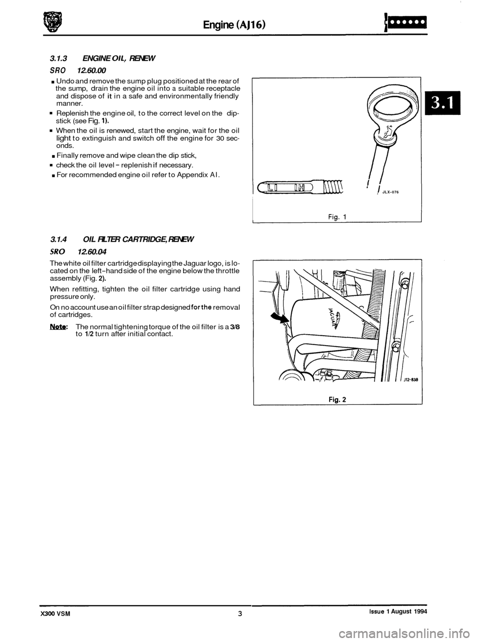
3.1.3 ENGINE OIL, RENEW
SRO 12.60.00
. Undo and remove the sump plug positioned at the rear of
the sump, drain the engine oil into a suitable receptacle
and dispose of
it in a safe and environmentally friendly
manner.
Replenish the engine oil, to the correct level on the dip-
stick (see Fig. 1).
When the oil is renewed, start the engine, wait for the oil
light to extinguish and switch off the engine for 30 sec- onds.
. Finally remove and wipe clean the dip stick,
check the oil level - replenish if necessary.
. For recommended engine oil refer to Appendix AI.
3.1.4 OIL FILTER CARTRIDGE, RENEW
SRO 12.60.04
The white oil filter cartridge displaying the Jaguar logo, is lo- cated on the left-hand side of the engine below the throttle
assembly (Fig. 2).
When refitting, tighten the oil filter cartridge using hand
pressure only.
On no account use an oil filter strap designed
forthe removal
of cartridges.
m: The normal tightening torque of the oil filter is a 3/8 to 1/2 turn after initial contact.
1 JLX-076
Fig. 1
-~ ~ ~~~~~ Issue 1 August 1994 X300 VSM 3
Page 47 of 521
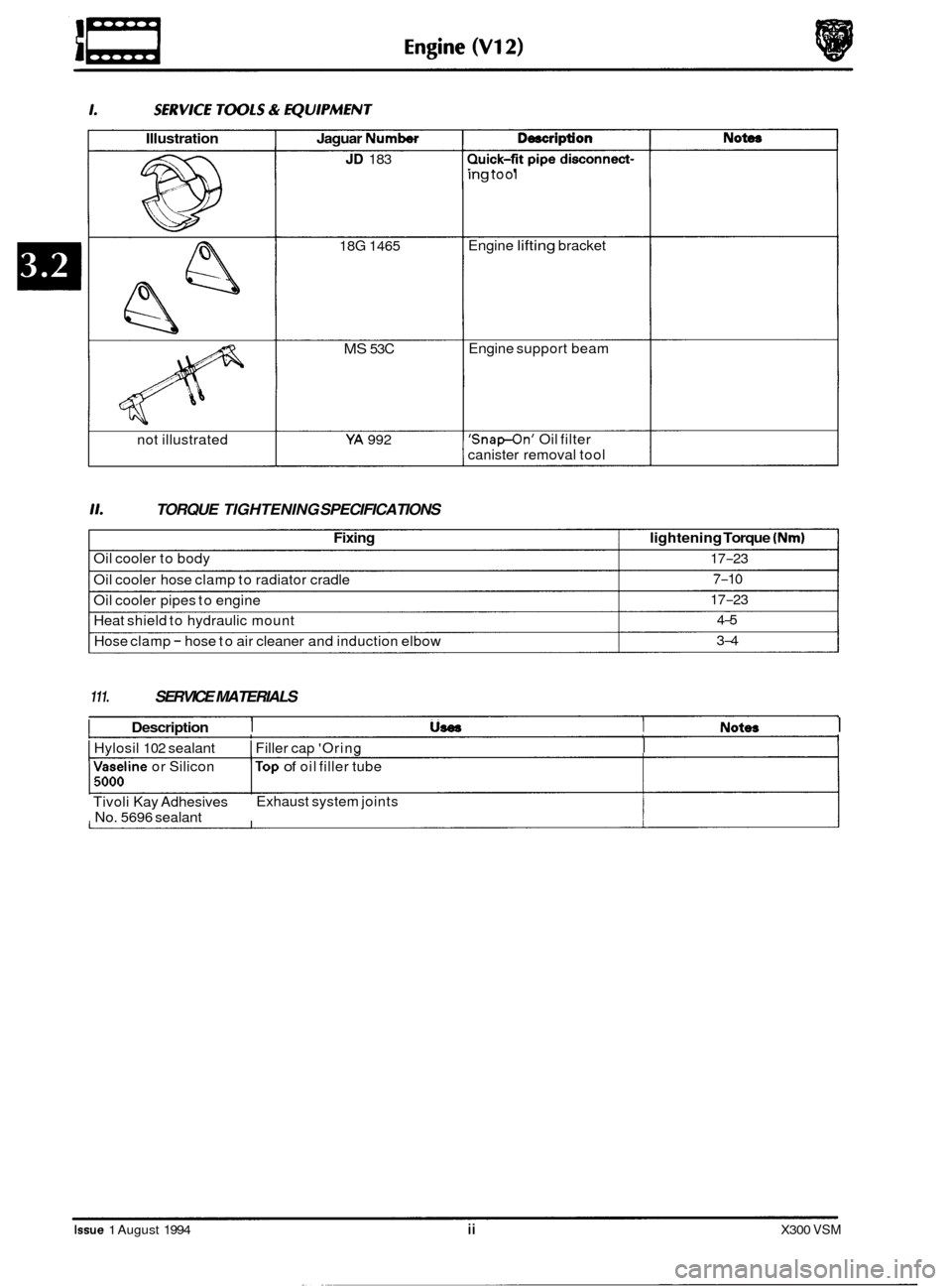
Illustration
not illustrated
Jaguar Number
JD 183
18G 1465
MS 53C
YA 992
11. TORQUE TIGHTENING SPECIFICATIONS
ing tool
Engine
lifting bracket
Engine support beam
'Snap-On' Oil filter
canister removal tool
Fixing lightening Torque (Nm)
Oil cooler to body 17-23
Oil cooler hose clamp to radiator cradle
Oil cooler pipes to engine
Heat shield to hydraulic mount
Hose clamp
- hose to air cleaner and induction elbow
7-10
17
-23
4
-5
3
-4
111. SERVICE MATERIALS
I Description I US88 I Notem I
I Hylosil 102 sealant I Filler cap 'Oring I I
Vaseline or Silicon lTop of oil filler tube 15000
Tivoli Kay Adhesives
No. 5696 sealant Exhaust
system joints
Issue 1 August 1994 ii X300 VSM
Page 55 of 521
€3 Cooling System (AJ16)
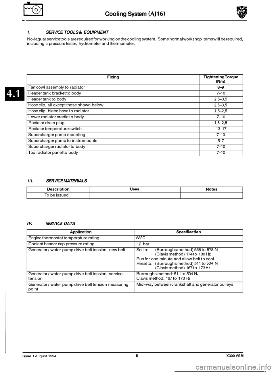
Fixing
Fan cowl assembly to radiator
Header tank bracket to body
Header tank to body
Hose clip,
all except those shown below
Hose clip, bleed hose to radiator
Radiator drain plug
Radiator temperature switch
Lower
radiator cradle to body
Supercharger pump mounting
Supercharger pump to instrumounts
Supercharger radiator to body
Top radiator panel to body
1. SERVICE TOOLS & EQUIPMENT
No Jaguar service tools are required for working on the cooling system. Some normal workshop items will be required,
including
a pressure tester, hydrometer and thermometer.
Tightening Torque
(Nm)
8-9
7-1 0
2,5-3,5
2,5-3,5
1,5-2,5
1,5-2,5
13-17
7
-1 0
7-10
5-7
7-10
7
-10
Description UseS
To be issued
111. SERVICE MATERIALS
Notes
Iv: SZRVICE DATA
Application
Engine thermostat temperature rating
Coolant header cap pressure rating
Generator
/ water pump drive belt tension, new belt
Generator
/ water pump drive belt tension, service
tension
_____ ~~ Generator / water
pump drive belt tension measuring
point
Smcification
88OC
1,2 bar
Set to:
Run for one minute and allow belt to cool.
Reset to: (Burroughs method) 511 to
534 N;
Burroughs method: 51 1 to 534 N.
Clavis method: 167 to 173 Hz
Mid
-way between crankshaft and generator pulleys
(Burroughs method)
556 to 578
N;
(Clavis method) 174 to 180 Hz.
(Clavis method) 167 to 173
Hz
0
0
0
0
X300 VSM Issue 1 August 1994 ii
Page 58 of 521
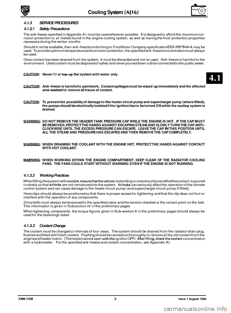
area washed to remove all traces of coolant.
CAUTION: To prevent the possibility of damage to the heater circuit pump and supercharger pump (where fitted),
the pumps should be electrically isolated if the ignition has to be turned ON while the cooling system is
drained.
WARNING: DO NOT REMOVE THE HEADER TANK PRESSURE CAP WHILE THE ENGINE IS HOT. IF THE CAP MUST
BE REMOVED, PROTECT THE HANDS AGAINST ESCAPING STEAM AND SLOWLY TURN THE CAP ANTI
- CLOCKWISE UNTIL THE EXCESS PRESSURE CAN ESCAPE. LEAVE THE CAP IN THIS POSITION UNTIL
ALL THE STEAM AND PRESSURE HAS ESCAPED AND THEN REMOVE THE CAP COMPLETELY.
WARNING: WHEN DRAINING THE COOLANT WITH THE ENGINE HOT, PROTECT THE HANDS AGAINST CONTACT
WITH HOT COOLANT.
WARNING: WHEN WORKING WITHIN THE ENGINE COMPARTMENT, KEEP CLEAR OF THE RADIATOR COOLING
FANS. THE FANS COULD START WITHOUT WARNING EVEN IF THE ENGINE IS NOT RUNNING.
4.1.3.2 Working Practices
Whenfilling thesystem with coolant,ensurethatthevehicle isstanding on a level surfaceandthatthecoolant is poured
in slowly so that airlocks are not introduced into the system. Airlocks can seriously affect the operation of the climate
control system and can cause damage to the heater circuit pump (and supercharger circuit pump if fitted).
Cooling System (AJ16)
4.1.3 SERVICE PROCEDURES
4.1.3.1 Safety Precautions
The anti-freeze specified in Appendix AI must be used wherever possible. It is designed to afford the maximum cor- rosion protection to all metals found in the engine cooling system, as well as having the frost protection properties
necessary during the winter months.
Should
it not be available, then anti-freeze conforming to Ford Motor Company specification ESLbM97B49-A may be
used. To provide optimum temperature and corrosion protection, the specified anti-freeze concentration must always
be used.
Once coolant has been drained from the system,
it must be discarded and not reused. Anti-freeze is harmful to the
environment. Used coolant must be disposed of safely and never poured down a drain connected to the public sewer.
CAUTION: Never fill or topup the system with water only.
CAUTION : Anti-freeze is harmful to paintwork. Coolant spillages must be wiped up immediately and the affected
Hose clips should always be positioned so that there is proper access for tightening and that the clip does not foul or
interfere with the operation of any components.
Drive belts must always be tensioned to the specified value and the tension checked
at the correct point on the belt.
This information is given in Subsection IV in the preliminary pages.
0
When tightening components, the torque figures given in Sukection II in the preliminary pages should always be
used for the fastenings listed.
4.1.3.3 Coolant Change
The coolant must be changed at intervals of four years. The system should be drained from the radiator drain plug,
flushed and filled with fresh coolant. Flushing should be carried out thoroughly to remove all the old coolant from the
engineand heater matrix. (The heatervalve isopen withthe ignition OFF). AfterfiIling,checkthecoolant concentration
with a hydrometer. For the specified anti-freeze and coolant concentration, see Appendix AI.
X300 VSM 3 Issue 1 August 1994