mirror JAGUAR XJ6 1994 2.G Workshop Manual
[x] Cancel search | Manufacturer: JAGUAR, Model Year: 1994, Model line: XJ6, Model: JAGUAR XJ6 1994 2.GPages: 521, PDF Size: 17.35 MB
Page 10 of 521
Introduction i
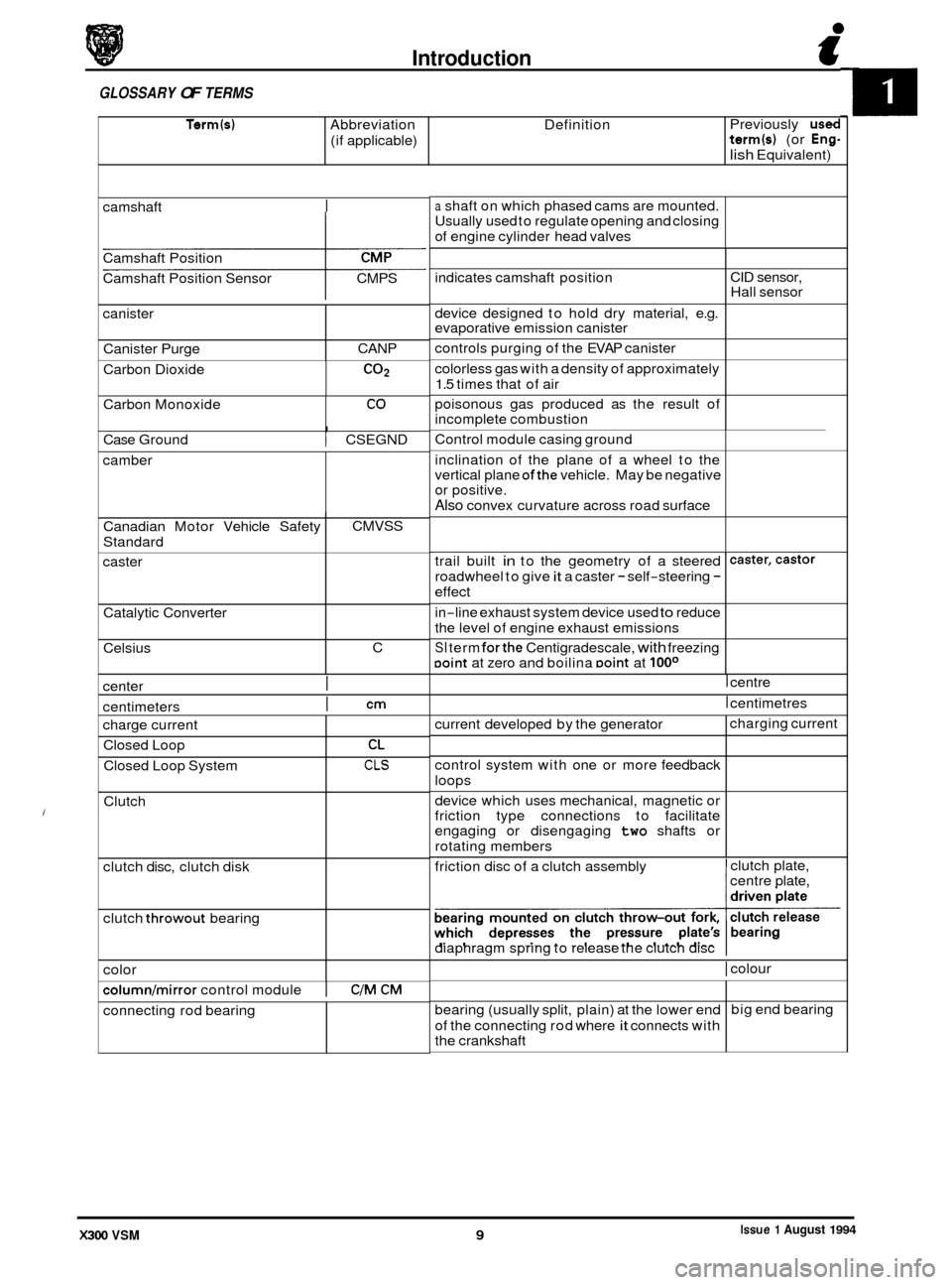
Term(s) Abbreviation Definition
(if applicable)
GLOSSARY OF TERMS
Previously used term(s) (or Eng-
lish Equivalent)
indicates camshaft position
device designed to hold dry material, e.g.
evaporative emission canister
controls purging of the EVAP canister
colorless gas with a density of approximately
1.5 times that of air
poisonous gas produced as the result of
incomplete combustion
camshaft
I
CID
sensor,
Hall sensor
Camshaft
Position
Camshaft Position Sensor CMPS
canister
Canister Purge CANP
Carbon Dioxide
CO2
I Case Ground I CSEGND
Carbon
Monoxide
camber
CO
Canadian Motor Vehicle Safety
Standard
caster
Catalytic Converter
Celsius
center
I
CMVSS
C
centimeters
I cm
trail built in to the geometry of a steered
roadwheel to give
it a caster - self-steering -
effect
caster,castor
color
columnlmirror control module I C/M CM
charge current
Closed Loop
Closed Loop System
Clutch
clutch disc, clutch disk
clutch
throwout bearing
connecting rod bearing
CL
CLS
a shaft on which phased cams are mounted.
Usually used to regulate opening and closing
of engine cylinder head valves
current developed by the generator
control system with one or more feedback
loops
device which uses mechanical, magnetic or
friction type connections to facilitate
engaging or disengaging
two shafts or
rotating members charging
current
Control
module casing ground
inclination of the plane of a wheel to the
vertical plane
ofthe vehicle. May be negative
or positive.
Also convex curvature across road surface
bearing (usually split, plain) at the lower end
of the connecting rod where
it connects with
the crankshaft big
end bearing
in
-line exhaust
system device used to reduce
the level of engine exhaust emissions
SI term forthe Centigradescale, with freezing Doint at zero and boilina Doint at looo
I centre
I centimetres
friction disc of a clutch assembly clutch
plate,
centre plate,
diaphragm spring to release the clutch disc
I colour
Issue 1 August 1994 X300 VSM 9
Page 252 of 521
Body Components & Trim .
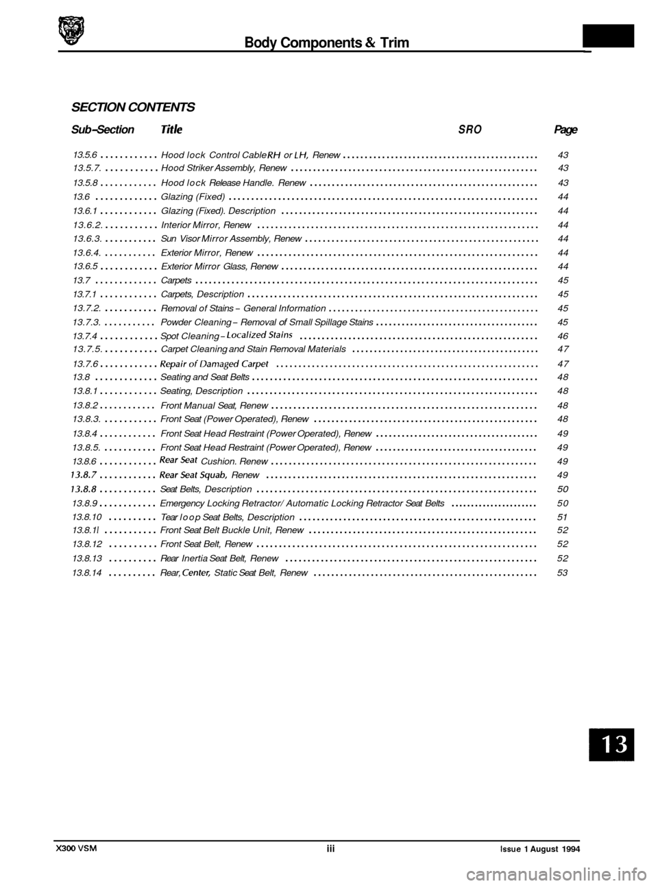
SECTION CONTENTS
Sub-Section Title SRO Page
13.5.6 ............ Hood lock Control Cable RH or LH, Renew ............................................. 43
13.5.7.
........... Hood Striker Assembly, Renew ........................................................ 43
Hood lock Release Handle. Renew
.................................................... 43
13.5.8 ............
13.6 ............. Glazing (Fixed) ..................................................................... 44
13.6.1
............ Glazing (Fixed). Description .......................................................... 44
13.6.2.
........... Interior Mirror, Renew ............................................................... 44
13.6.3.
........... Sun Visor Mirror Assembly, Renew ..................................................... 44
13.6.4.
........... Exterior Mirror, Renew ............................................................... 44
13.6.5
............ Exterior Mirror Glass, Renew .......................................................... 44
13.7
............. Carpets ........................................................................\
.... 45
13.7.1
............ Carpets, Description ................................................................. 45
13.7.2.
........... Removal of Stains - General Information ................................................ 45
13.7.3.
........... Powder Cleaning - Removal of Small Spillage Stains ...................................... 45
13.7.4
............ Spot Cleaning- LocalizedStains ...................................................... 46
13.7.6
............ RepairofDamagedCarpet ........................................................... 47
e
13.7.5. ........... Carpet Cleaning and Stain Removal Materials ........................................... 47
13.8
............. Seating and Seat Belts ................................................................ 48
13.8.1
............ Seating, Description ................................................................. 48
Front Manual Seat, Renew
............................................................ 48
13.8.3.
........... Front Seat (Power Operated), Renew ................................................... 48
13.8.2
............
13.8.4 ............ Front
Seat Head Restraint (Power Operated), Renew ...................................... 49
13.8.5.
........... Front Seat Head Restraint (Power Operated), Renew ...................................... 49
13.8.6
............ RearSeat Cushion. Renew ............................................................ 49
13.8.7 ............ RearSeatSquab. Renew ............................................................. 49
73.8.8 ............ Seat Belts, Description ............................................................... 50
13.8.9 ............ Emergency Locking Retractor/ Automatic Locking Retractor Seat Belts ...................... 50
13.8.10
.......... Tear loop Seat Belts, Description ...................................................... 51
13.8.1 I ........... Front Seat Belt Buckle Unit, Renew .................................................... 52
13.8.12
.......... Front Seat Belt, Renew ............................................................... 52
13.8.13
.......... Rear Inertia Seat Belt, Renew ......................................................... 52
13.8.14
.......... Rear, Center, Static Seat Belt, Renew ................................................... 53
iii Issue 1 August 1994
Page 256 of 521
Body Components & Trim
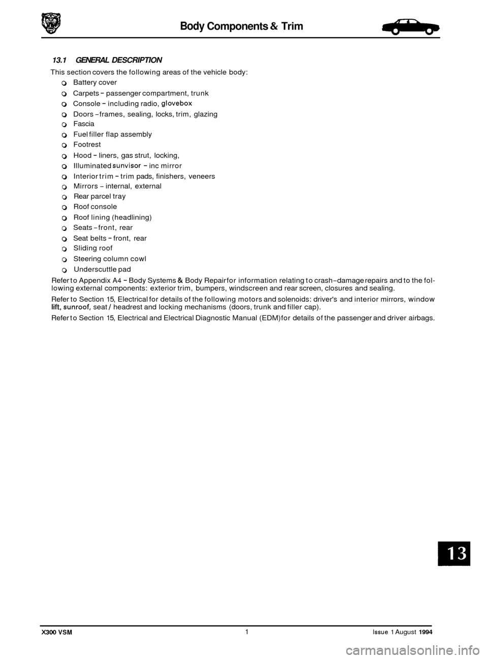
13.1 GENERAL DESCRIPTION
This section covers the following areas of the vehicle body:
0 Battery cover
0 Carpets - passenger compartment, trunk
0 Console - including radio, glovebox
0 Doors -frames, sealing, locks, trim, glazing
0 Fascia
0 Fuel filler flap assembly
0 Footrest
0 Hood - liners, gas strut, locking,
0 Illuminated sunvisor - inc mirror
0 Interior trim - trim pads, finishers, veneers
0 Mirrors - internal, external
0 Rear parcel tray
0 Roof console
0 Roof lining (headlining)
o Seats -front, rear -
0 Seat belts - front, rear
0 Sliding roof
0 Steering column cowl
0 Underscuttle pad
Refer to Appendix
A4 - Body Systems & Body Repair for information relating to crash-damage repairs and to the fol- lowing external components: exterior trim, bumpers, windscreen and rear screen, closures and sealing.
Refer to Section 15, Electrical for details of the following motors and solenoids: driver's and interior mirrors, window
lift, sunroof, seat / headrest and locking mechanisms (doors, trunk and filler cap).
Refer to Section 15, Electrical and Electrical Diagnostic Manual (EDM) for details of the passenger and driver airbags.
X300 VSM 1 Issue 1 August 1994
Page 257 of 521

Body Components & Trim d-!P
13.2
13.2.1 Doors, Description
Doors are of welded, mild steel frames welded to the door panels; sponge rubber primary and secondary seals are
mounted on the doors. Internal insulation is provided by a foam water shedder attached to the door by press fitting and doublesided adhesive tape.
Front and rear door armrests are attached to supports riveted to each door frame; the attaching screws are fitted
with access covers. Upper and lower trim pads and a door pocket are attached to each of the doors by clips and screws. multi-plug connectors are used to provide a means of connecting the guard lamps, window lift switches and loud- speakers, external mirror and regulator (front doors only), which are housed within the doors.
Central locking is provided subject to market variations: Dead Locking for UK
/ Europe and Driver only unlock for N America. Door locks are eight disc, bayonet fixing, barrels with integral lock / unlock switches. Keys include ‘in-key’
transponders which are programmed to the vehicle via the Jaguar Diagnostic System also operate the engine immobi
- lisation system.
CAUTION: When removing the door panel water shedder, a foam membrane attached to each door panel by a com- bination of pressfitting (upper area) and bydouble-sided tape (bottom area), it is important that the shed- der is refitted correctly to maintain the water seal.
It is advisable not to disturb the bottom (taped) portion of the water shedder unless absolutely necessary
- it is possible to unclip the top of the shedder and bend it over to gain access to the inner panel.
If
it is necessary to disturb the bottom attachment, eg to remove the water shedder from the door panel,
the existing water shedder must be discarded and a new one fitted to ensure that the seal is maintained.
On refitting, the new water shedder should be pressed onto the door panel at the top and then the adhes- ive tape backing strip peeled off to enable the shedder to be pressed home at the bottom.
DOORS AND FUEL FILLER FLAP
13.2.2 front and Rear Door Trim Pad Veneer Panel,
Renew
SRO 76.47.11
76.47.12
. Reposition the inner door handle. See Fig. 1.
Remove the inner handle escutcheon plate blanking plate.
Undo and remove the inner handle escutcheon plate se-
. Remove the plate and gasket.
. Carefully Undo and remove the veneer panel.
Undo and remove the retaining clip securing screws.
. Remove the retaining clip assemblies.
9 Place the veneer panel aside.
Place the new veneer panel to the front.
Fit the retaining clip assemblies.
. Fit and tighten the retaining clip securing screws.
. Fit and fully seat the veneer panel to the door.
. Reposition the inner door handle.
. Fit the gasket and plate over the inner door handle.
. Fit and tighten the escutcheon plate securing screw.
. Refit the blanking plate.
curing
screw.
Fig.
1
0
0
0
0
Issue 1 August 1994 2 X300 VSM
Page 299 of 521
Body Components & Trim #ib
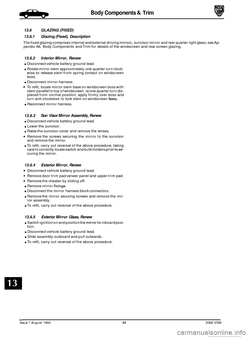
13.6 GLAZING (FIXED)
13.6.1 Glazing (Fixed), Description
The fixed glazing comprises internal and external driving mirrors, sunvisor mirror and rear quarter light glass; see Ap- pendix A4, Body Components and Trim for details of the windscreen and rear screen glazing.
13.6.2 Interior Mirror, Renew
. Disconnect vehicle battery ground lead.
. Rotate mirror stem approximately one quarter turn clock- wise to release stem from spring contact on windscreen
boss.
. Disconnect mirror harness.
To refit, locate mirror stem base on windscreen boss with
stem parallel to top of windscreen, ie one quarter turn dis- placed from normal position; apply firmly over boss and
turn anti-clockwise to lock stem on windscreen boss.
. Reconnect mirror harness.
13.6.3
. Disconnect vehicle battery ground lead.
. Lower the sunvisor.
. Raise the sunvisor cover and remove the lenses.
Remove the screws securing the mirror to the sunvisor
and remove the mirror.
. To refit, carry out reversal of the above procedure, taking
care to correctly locate switch and bulb holders priortose-
curing the mirror.
Sun Visor Mirror Assembly, Renew
13.6.4 Exterior Mirror, Renew
= Disconnect vehicle battery ground lead.
Remove door trim pad veneer panel and upper trim pad.
9 Remove the cheater by sliding off.
. Remove mirror fixings.
. Disconnect the mirror harness block connectors.
. Remove the mirror securing screws and remove the mir-
ror assembly.
. To refit, carry out reversal of the above procedure.
13.6.5 Exterior Mirror Glass, Renew
. Switch ignition on and position the mirrorto inboard posi-
. Disconnect vehicle battery ground lead.
. Slide assembly outboard and pull outwards.
. To refit, carry out reversal of the above procedure.
tion.
Issue 1 August 1994 44 X300 VSM
Page 303 of 521
Body Components & Trim a
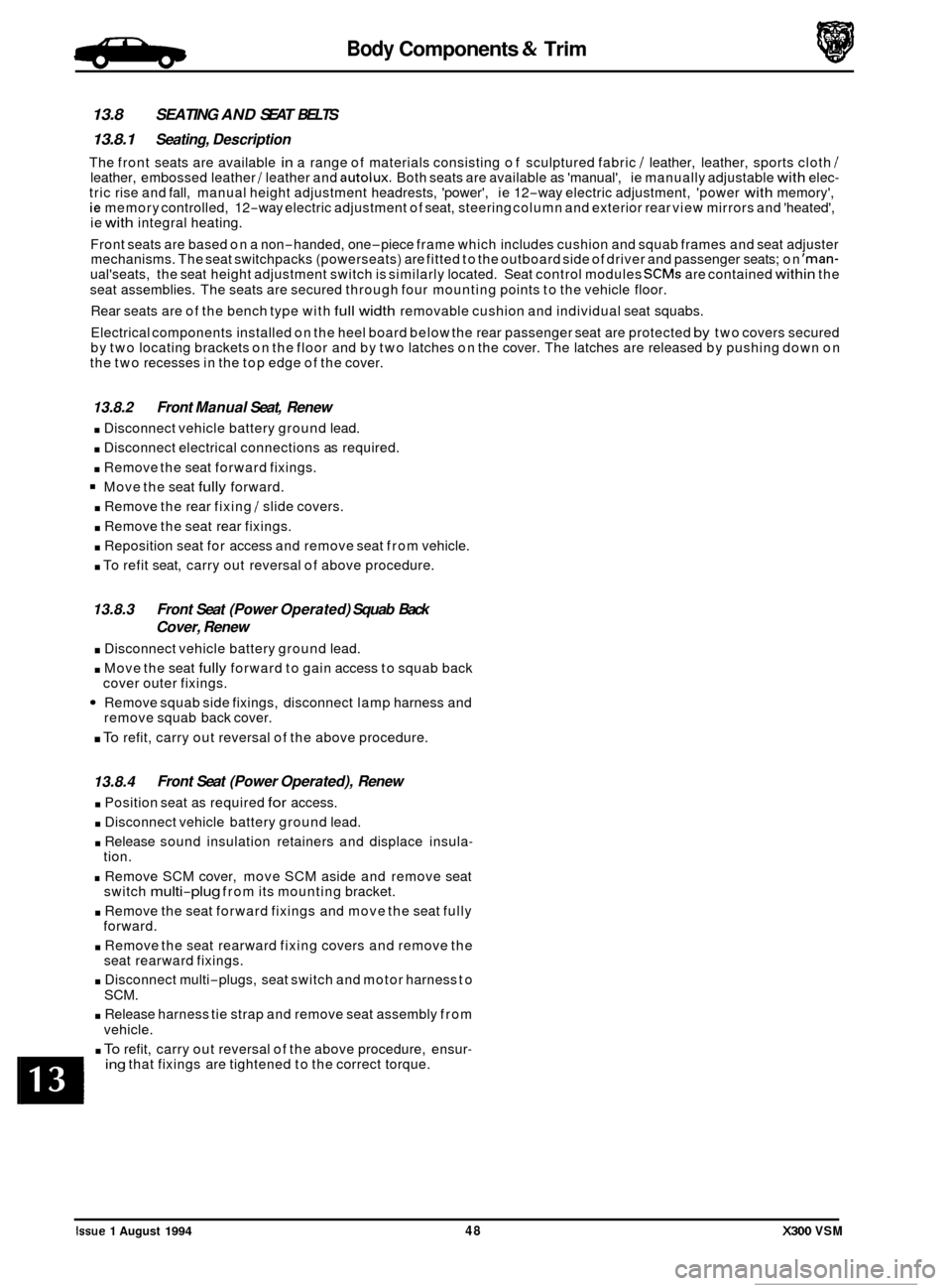
13.8 SEATING AND SEAT BELTS
13.8.1 Seating, Description
The front seats are available in a range of materials consisting of sculptured fabric / leather, leather, sports cloth / leather, embossed leather / leather and autolux. Both seats are available as 'manual', ie manually adjustable with elec- tric rise and fall, manual height adjustment headrests, 'power', ie 12-way electric adjustment, 'power with memory', ie memory controlled, 12-way electric adjustment of seat, steering column and exterior rear view mirrors and 'heated',
ie with integral heating.
Front seats are based on a non
-handed, one-piece frame which includes cushion and squab frames and seat adjuster
mechanisms. The seat switchpacks (powerseats) are fitted to the outboard side of driver and passenger seats; on 'man- ual'seats, the seat height adjustment switch is similarly located. Seat control modules SCMs are contained within the
seat assemblies. The seats are secured through four mounting points to the vehicle floor.
Rear seats are of the bench type with
full width removable cushion and individual seat squabs.
Electrical components installed on the heel board below the rear passenger seat are protected
by two covers secured
by two locating brackets on the floor and by two latches on the cover. The latches are released by pushing down on
the two recesses in the top edge of the cover.
13.8.2 Front Manual Seat, Renew
. Disconnect vehicle battery ground lead.
. Disconnect electrical connections as required.
. Remove the seat forward fixings.
Move the seat fully forward.
. Remove the rear fixing / slide covers.
. Remove the seat rear fixings.
. Reposition seat for access and remove seat from vehicle.
. To refit seat, carry out reversal of above procedure.
13.8.3
. Disconnect vehicle battery ground lead.
. Move the seat fully forward to gain access to squab back
Remove squab side fixings, disconnect lamp harness and
. To refit, carry out reversal of the above procedure.
Front Seat (Power Operated) Squab Back
Cover, Renew
cover outer fixings.
remove squab back cover.
13.8.4
. Position seat as required for access.
. Disconnect vehicle battery ground lead.
. Release sound insulation retainers and displace insula-
. Remove SCM cover, move SCM aside and remove seat
. Remove the seat forward fixings and move the seat fully
. Remove the seat rearward fixing covers and remove the
. Disconnect multi-plugs, seat switch and motor harness to
. Release harness tie strap and remove seat assembly from
Front Seat (Power Operated), Renew
tion.
switch
multi-plug from its mounting bracket.
forward. seat rearward fixings.
SCM.
vehicle.
. To refit, carry out reversal of the above procedure, ensur- ing that fixings are tightened to the correct torque.
Issue 1 August 1994 48 X300 VSM
0
0
0
Page 318 of 521
Climate Control Systems
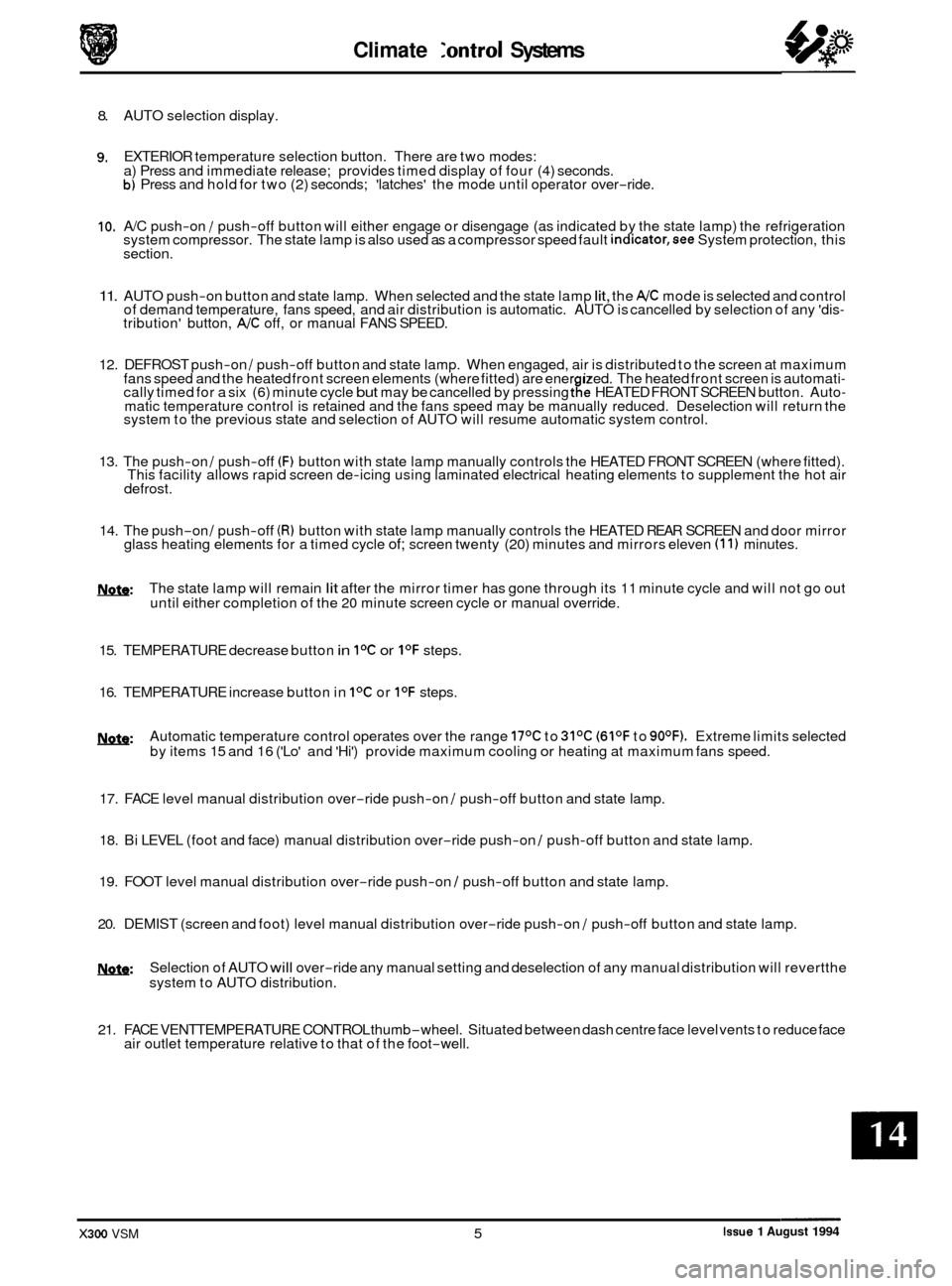
8. AUTO selection display.
9. EXTERIOR temperature selection button. There are two modes:
a) Press and immediate release; provides timed display of four (4) seconds.
b) Press and hold for two (2) seconds; 'latches' the mode until operator over-ride.
10. A/C push-on / push-off button will either engage or disengage (as indicated by the state lamp) the refrigeration
system compressor. The state lamp is also used as a compressor speed fault indicator,see System protection, this
section.
11. AUTO push-on button and state lamp. When selected and the state lamp lit, the A/C mode is selected and control
of demand temperature, fans speed, and air distribution is automatic. AUTO is cancelled by selection of any 'dis- tribution' button, A/C off, or manual FANS SPEED.
12. DEFROST push
-on / push-off button and state lamp. When engaged, air is distributed to the screen at maximum
fans speed and the heated front screen elements (where fitted) are ener ized. The heated front screen is automati- cally timed for a six (6) minute cycle but may be cancelled by pressing tfe HEATED FRONT SCREEN button. Auto- matic temperature control is retained and the fans speed may be manually reduced. Deselection will return the
system to the previous state and selection of AUTO will resume automatic system control.
13. The push
-on / push-off (F) button with state lamp manually controls the HEATED FRONT SCREEN (where fitted).
This facility allows rapid screen de-icing using laminated electrical heating elements to supplement the hot air
defrost.
14. The push-on / push-off (R) button with state lamp manually controls the HEATED REAR SCREEN and door mirror
glass heating elements for a timed cycle of; screen twenty (20) minutes and mirrors eleven (1 1) minutes.
m: The state lamp will remain lit after the mirror timer has gone through its 11 minute cycle and will not go out
until either completion of the 20 minute screen cycle or manual override.
15. TEMPERATURE decrease button
in IoC or I0F steps.
16. TEMPERATURE increase button in
IoC or I0F steps.
w: Automatic temperature control operates over the range 17OC to 31OC (61OF to 90OF). Extreme limits selected
by items 15 and 16 ('Lo' and 'Hi') provide maximum cooling or heating at maximum fans speed.
17. FACE level manual distribution over
-ride push-on / push-off button and state lamp.
0 18. Bi LEVEL (foot and face) manual distribution over-ride push-on / push-off button and state lamp.
19. FOOT level manual distribution over
-ride push-on / push-off button and state lamp.
20. DEMIST (screen and foot) level manual distribution over
-ride push-on / push-off button and state lamp.
!Y&Q: Selection of AUTO will over-ride any manual setting and deselection of any manual distribution will revertthe
system to AUTO distribution.
21. FACE VENTTEMPERATURE CONTROL thumb
-wheel. Situated between dash centre face level vents to reduce face
air outlet temperature relative to that of the foot-well.
Issue 1 August 1994 X300 VSM 5
Page 320 of 521
Climate Control Systems
Manual Inputs
Automatic inputs
outputs
14.5 AIR CONDITIONING CONTROL MODULE (A/CCM)
14.5.1 Description
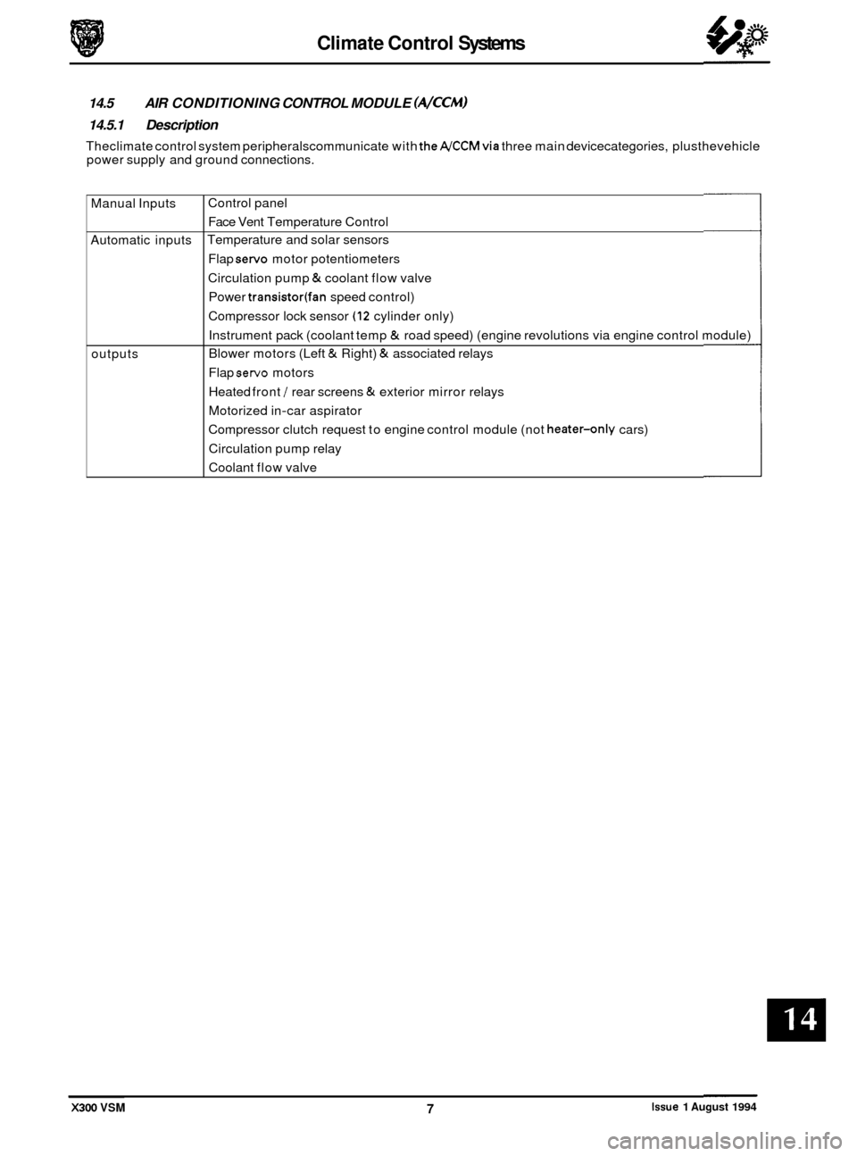
Theclimate control system peripheralscommunicate with theA/CCMvia three main devicecategories, plusthevehicle
power supply and ground connections.
Control panel Face Vent Temperature Control
Temperature and solar sensors
Flap
servo motor potentiometers
Circulation pump
& coolant flow valve
Power
transistor(fan speed control)
Compressor lock sensor
(12 cylinder only)
Instrument pack (coolant temp
& road speed) (engine revolutions via engine control module)
Blower motors (Left
& Right) & associated relays
Flap
servo motors
Heated front
/ rear screens & exterior mirror relays
Motorized in
-car aspirator
Compressor clutch request to engine control module (not
heater-only cars)
Circulation pump relay
Coolant flow valve
X300 VSM Issue 1 August 1994 7
Page 321 of 521
Climate Control Systems
. Centre vent flap
Foot flap
Defrost flap
I I
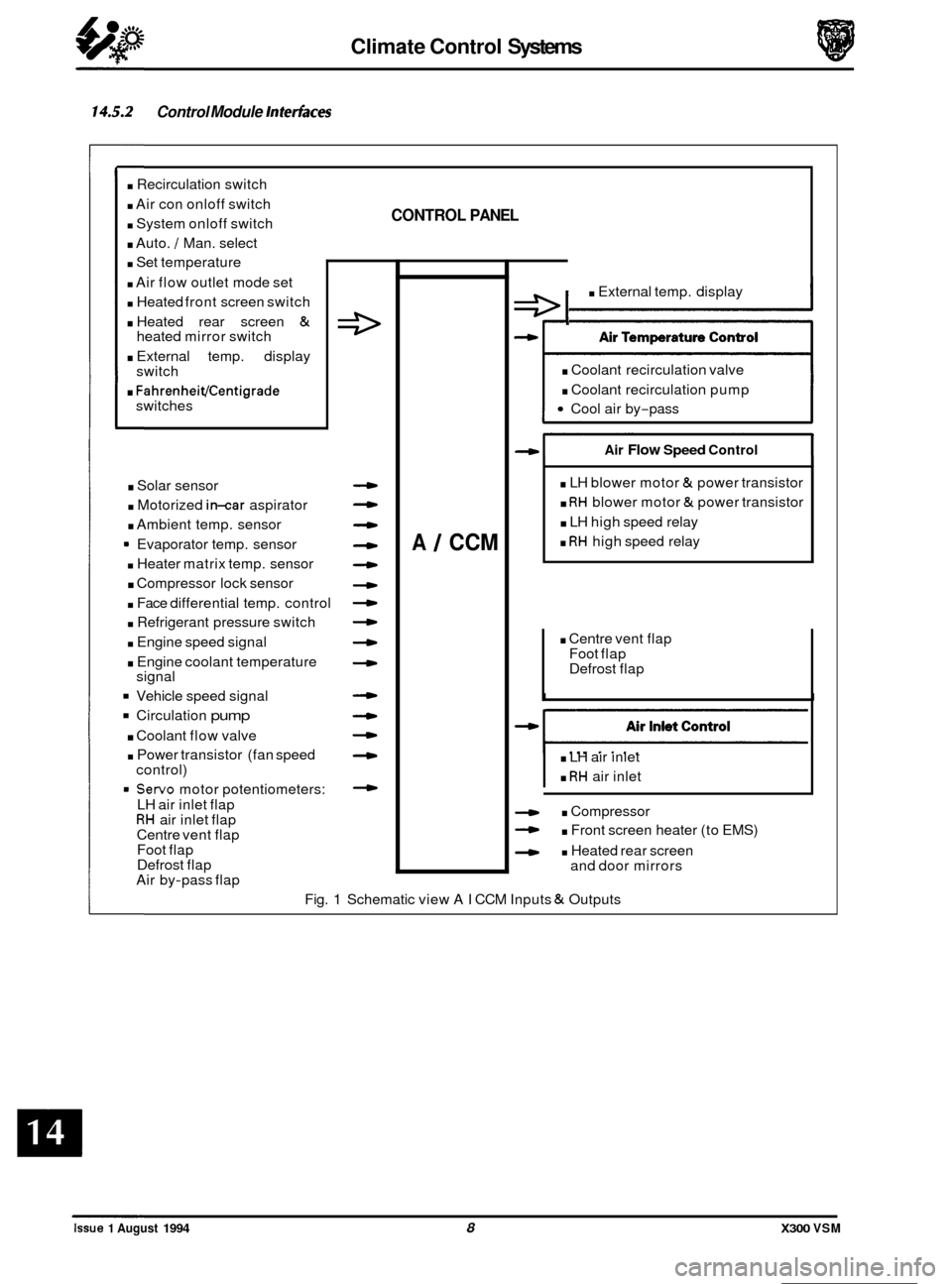
14.5.2 Control Module Interfaces
. Recirculation switch
. Air con onloff switch
. System onloff switch
. Auto. / Man. select
. Set temperature
. Air flow outlet mode set
. Heated front screen switch
. Heated rear screen &
. External temp. display
. FahrenheiVCentigrade
heated mirror switch
switch
switches
. Solar sensor
. Motorized in-car aspirator
. Ambient temp. sensor
9 Evaporator temp. sensor
. Heater matrix temp. sensor
. Compressor lock sensor
. Face differential temp. control
. Refrigerant pressure switch
. Engine speed signal
. Engine coolant temperature
Vehicle speed signal
Circulation pump
. Coolant flow valve
. Power transistor (fan speed
= Servo motor potentiometers:
signal
control)
LH air inlet flap
RH air inlet flap
Centre vent flap
Foot flap
Defrost flap
Air by
-pass flap
CONTROL PANEL
4
-
4
4
4
4
4
4
A 1 CCM
e I . External temp. display
. Coolant recirculation valve
. Coolant recirculation pump
Cool air by-pass
Air Flow Speed Control
. LH blower motor & power transistor
. RH blower motor & power transistor
. LH high speed relay
. RH high speed relay
. LH air inlet
. RH air inlet
. Compressor
- . Front screen heater (to EMS)
- . Heated rear screen
and door mirrors
Fig.
1 Schematic view AI CCM Inputs & Outputs
0
0
0
0
Issue 1 August 1994 8 X300 VSM
Page 328 of 521
Climate Control Systems
14.10 FAULT DIAGNOSIS
14.10.1 Introduction
It is very important to positively identifythe area of concern before starting a rectification procedure. A little time spent
with your customer to identify the conditions under which a problem occurs will be beneficial. Relevant criteria are:
Weather conditions, ambient temperature, intermittent or continuous fault, airflow fault, temperature control fault, dis
- tribution fault and air inlet problem.
14.10.2 Functional Check
This simple 'first line check' will allow you to ascertain whether the system is operating within its design parameters,
without recourse to (JDE). Please carry out the following, in order.
0 Start engine and attain normal running temperature.
0 Presss AUTO to display selected temperature and illuminate AUTO & AJC state lamps.
0 Rotate FAN to increase or decrease lower speed, verify bar graph representation.
0 Operate AJC to toggle on or off. Because the compressor can be inhibited by the engine management system,
ensure that the engine temperature is normal and that the ambient is above 5O C.
0 Operate RECIRC, state lamp should be lit and the flap behind the blower grille open.
0 Operate distribution buttons in turn, verify correct air distribution and relevant state lamp.
0 Operate DEFROST, check max fans and air to front screen.
0 Cycle TEMPERATURE to 'Hi' and 'Lo' to verify demanded variations and display operation. Note that extremes
will provide max heat or cold independent of in-car temperature.
0 Operate EX to toggle between ambient and control temperatures.
0 Operate HFS and HRW to note timer and mirror operation.
0 Initiate System Self Test to check for, and extract, stored faults should any of the above not perform as stated.
14.10.3 System symptoms
There are five basic symptoms associated with air conditioning fault diagnosis. The following conditions are not in order of priority.
No Cooling
0 Is the electrical circuit to the compressor clutch functional?
0 Is the electrical circuit to the blower motor(s) functional?
0 Slack or broken compressor drive belt.
0 Compressor partially or completely seized.
0 Compressor shaft seal leak.
0 Compressor valve or piston damage (may be indicated by small variation between HIGH &LOW side pressures
relative to engine speed).
0 Broken refrigerant pipe (causing total loss of refrigerant).
0 Leak in system (causing total loss of refrigerant) - possible code 23.
0 Blocked filter in the receiver drier.
0 Evaporator sensor disconnected - possible code 13.
0 Pressure switch faulty - possible code 23.
X300 VSM Issue 1 August 1994