seat memory JAGUAR XJ6 1994 2.G Workshop Manual
[x] Cancel search | Manufacturer: JAGUAR, Model Year: 1994, Model line: XJ6, Model: JAGUAR XJ6 1994 2.GPages: 521, PDF Size: 17.35 MB
Page 200 of 521
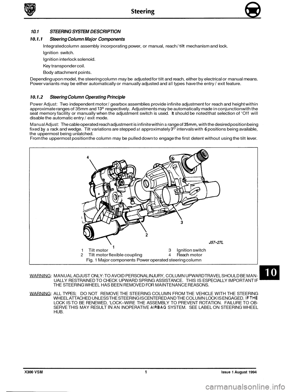
10.1 STEERING SYSTEM DESCRIPTION
10.1.1 Steering Column Major Components
Integrated column assembly incorporating power, or manual, reach /tilt mechanism and lock.
Ignition switch.
Ignition interlock solenoid.
Key transponder coil.
Body attachment points.
Depending upon model, the steering column may be adjusted for
tilt and reach, either by electrical or manual means.
Power variants may be either automatically or manually adjusted and all types have the entry / exit feature.
10.1.2 Steering Column Operating Principle
Power Adjust: Two independent motor / gearbox assemblies provide infinite adjustment for reach and height within
approximate ranges of 35mm and
13O respectively. Adjustments may be automatically made in conjunction with the
seat memory facility or manually when the adjustment switch is used. It should be noted that selection of 'Off will
disable the automatic entry / exit mode.
Manual Adjust: The cable operated reach adjustment is infinite within a range of 35mm, with the desired position being
fixed
by a rack and wedge. Tilt variations are stepped at approximately 3O intervals with 6 positions being available,
the uppermost being unlatched.
From the uppermost position the column may be pulled down to engage the first detent without using the
tilt lever.
WARNING: MANUAL ADJUST ONLY: TO AVOID PERSONAL INJURY, COLUMN UPWARD TRAVEL SHOULD BE MAN- UALLY RESTRAINED TO CHECK UPWARD SPRING ASSISTANCE. THIS IS ESPECIALLY IMPORTANT IF
THE STEERING WHEEL HAS BEEN REMOVED FOR MAINTENANCE REASONS.
WARNING: ALL TYPES; DO NOT REMOVE THE STEERING COLUMN FROM THE VEHICLE WITH THE STEERING
WHEEL ATTACHED UNLESS THE STEERING
IS CENTERED AND THE COLUMN LOCK IS ENGAGED. IFTHE
SERVE THIS MAY RESULT IN AN INOPERATIVE AIRBAG SYSTEM. SEE LABEL ON STEERING WHEEL
HUB. LOCK IS TO BE RENEWED, 'LOCK-WIRE THE ASSEMBLY TO PREVENT ROTATION. FAILURE TO OB-
0
X300 VSM 1 Issue 1 August 1994
J57-27L
3 Ignition switch 1 1 Tilt motor 2 Tilt motor flexible coupling 4 Reach motor
Fig.
1 Major components Power operated steering column
Page 303 of 521
Body Components & Trim a
13.8 SEATING AND SEAT BELTS
13.8.1 Seating, Description
The front seats are available in a range of materials consisting of sculptured fabric / leather, leather, sports cloth / leather, embossed leather / leather and autolux. Both seats are available as 'manual', ie manually adjustable with elec- tric rise and fall, manual height adjustment headrests, 'power', ie 12-way electric adjustment, 'power with memory', ie memory controlled, 12-way electric adjustment of seat, steering column and exterior rear view mirrors and 'heated',
ie with integral heating.
Front seats are based on a non
-handed, one-piece frame which includes cushion and squab frames and seat adjuster
mechanisms. The seat switchpacks (powerseats) are fitted to the outboard side of driver and passenger seats; on 'man- ual'seats, the seat height adjustment switch is similarly located. Seat control modules SCMs are contained within the
seat assemblies. The seats are secured through four mounting points to the vehicle floor.
Rear seats are of the bench type with
full width removable cushion and individual seat squabs.
Electrical components installed on the heel board below the rear passenger seat are protected
by two covers secured
by two locating brackets on the floor and by two latches on the cover. The latches are released by pushing down on
the two recesses in the top edge of the cover.
13.8.2 Front Manual Seat, Renew
. Disconnect vehicle battery ground lead.
. Disconnect electrical connections as required.
. Remove the seat forward fixings.
Move the seat fully forward.
. Remove the rear fixing / slide covers.
. Remove the seat rear fixings.
. Reposition seat for access and remove seat from vehicle.
. To refit seat, carry out reversal of above procedure.
13.8.3
. Disconnect vehicle battery ground lead.
. Move the seat fully forward to gain access to squab back
Remove squab side fixings, disconnect lamp harness and
. To refit, carry out reversal of the above procedure.
Front Seat (Power Operated) Squab Back
Cover, Renew
cover outer fixings.
remove squab back cover.
13.8.4
. Position seat as required for access.
. Disconnect vehicle battery ground lead.
. Release sound insulation retainers and displace insula-
. Remove SCM cover, move SCM aside and remove seat
. Remove the seat forward fixings and move the seat fully
. Remove the seat rearward fixing covers and remove the
. Disconnect multi-plugs, seat switch and motor harness to
. Release harness tie strap and remove seat assembly from
Front Seat (Power Operated), Renew
tion.
switch
multi-plug from its mounting bracket.
forward. seat rearward fixings.
SCM.
vehicle.
. To refit, carry out reversal of the above procedure, ensur- ing that fixings are tightened to the correct torque.
Issue 1 August 1994 48 X300 VSM
0
0
0
Page 345 of 521
rl Electrical
15.1.6 Fire Hazard Infonnath
Thermal decomposition or combustion may produce dense smoke and other dangerous fumes which in fire situations
form
a highly toxic explosive.
In the event of fire the surrounding area must be evacuated and
all personnel kept well upwind of the area.
Full fire fighting protective gear and
a self contained breathing apparatus operating in the positive pressure mode must
be worn for combating fire. Material near fires must be cooled with water spray to prevent ignition.
Fires should be allowed to burn themselves
out if not threatening to life or property. If fire is threatening to life or prop- erty use copious quantities of water to extinguish.
15.1.7 Ventilath
Local exhaust ventilation designed by a professional engineer should be provided if vapours, fumes, or dusts are gen- erated whilst working with airbag module.
The latest issue of the manual for recommended practices on 'Industrial Ventilation' is available from the
ACGIH Com- mittee on Industrial Ventilation, PO Box 16153, Lansing, MI 48910, USA.
The need for local exhaust ventilation should be evaluated by a professional industrial hygienist.
15.1.8 Respiratory Precauth
To prevent the inhalation of dangerous fumes and dusts, an approved mask should be worn.
15.1.9 Eye Protection
Chemical protective goggles are recommended where there is a possibility of eye contact with the propellant.
Safety glasses with side shields are recommended for
all other operations.
15.1. I0 Protective Clothing
Approved protective gloves, overalls and shoes / boots should be worn.
15.1.1 1 Handling and Storage Precautions
Do not store airbag module near live electrical equipment or circuitry. Store in a dry environment at ambient tempera-
tures.
Good housekeeping and engineering practices should be employed to prevent the generation and accumulation of
dusts. Store in compliance with
all local state and federal regulations.
15.1.12 Driver And Passenger Airbag Modules Assembly / Removal / Service Instructions
Before starting work, ensure ignition switch is in 'IocK position, key is removed and negative terminal cable
is disconnected from the battery.
As the airbag is equipped with a back up power source and due to the risk of airbag being inadvertently
deployed, wait one minute or longer before starting work.
0 Disconnecting the battery cancels the memory for clock, radio, seats, mirrors, steering column and any other
components using battery power. Reset memory after work is completed.
0 Never use airbags from other vehicles, always use new parts.
0 After work is completed, reconnect battery and perform warning light check see diagnostic manual.
0 Never use electrical probes to check voltage or electrical resistance.
0 Disconnect the airbag before carrying out any work on, or in the vicinity of module, or when using electric weld- ing equipment.
0 Always ensure that battery negative has been disconnected for one minute or longer before commencing any
removal procedure.
EB
Issue 1 August 1994 4 X300 VSM
Page 380 of 521
86.52.01
86.91 -83
19.75.21
86.80.24
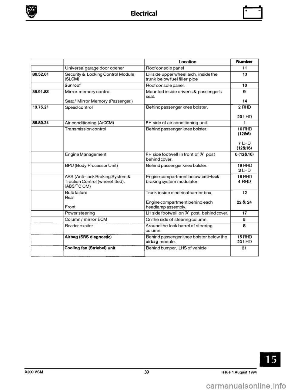
Universal garage door opener
Security
& Locking Control Module
(SLCM)
Sunroof
Mirror memory control
Seat
/ Mirror Memory (Passenger.)
Speed control
Air conditioning
(NCCM)
Transmission control
Engine Management
BPU (Body Processor Unit)
ABS (Anti
-lock Braking System &
Traction Control (where fitted).
(ABS/TC CM)
Bulb failure
Rear
Front
I Power steering
I Column / mirror ECM
Reader exciter
Location
Roof console panel
LH side upper wheel arch, inside the
trunk below fuel filler pipe
Roof console panel.
Mounted inside driver's
& passenger's
seat.
Behind passenger knee bolster.
RH side of air conditioning unit.
Behind passenger knee bolster.
RH side footwell in front of 'A' post
behind cover.
Behind passenger knee bolster.
Engine compartment below
anti-lock
braking system modulator.
Trunk inside electrical carrier box,
Engine compartment behind each
headlamp assembly.
LH side footwell on
'A' post, behind cover.
On the side of steering column.
Around the lock barrel of steering
column.
Behind passenger knee bolster below the
airbag module.
Behind bumper, LHS of vehicle
Numb
11
13
10
9
14
2
RHD
20 LHD
1
16
RHD
(1 2&6)
7 LHD
(12&16)
6 (12&16)
19 RHD
3 LHD
18 RHD
4 RHD
12
22
& 24
17 5
8
15 RHD
23 LHD
21
X300 VSM 39 issue 1 August 1994
Page 478 of 521
0
c
doors, windows, trunk, hood and sliding roof.
I Method I UK / EUROPE
of IXJ16I1SOVIIDAIM
Operation Sport XJ12 /DD6
Locking
Central locking Key X X X
Remote central locking Remote X X X
Deadlocking Remote/ X X X
Two stage unlock Remote/
- - - Key
Key
Drive away locks Auto X/DD X/DD X/DD
Switch
close
Interior trunk lid release Switch
Flush
sill buttons /
intrusion override
security
Security system (base)
Intrusion sensing (full)
Inclination sensing
Passive arming
Panic alarm
Audible tones (error
/
deadlock)
Engine immobilization
*
Auto
.,,,
Remote
Auto
1 XI X X
X D
D D
X/ DD
X
-~~
Security System - RESTRICTED ISSUE
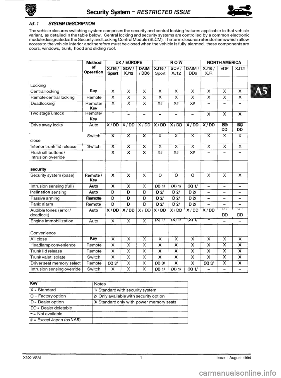
AS. 1 SYSTEM DESCRIPTION
The vehicle closures switching system comprises the security and central locking features applicable to that vehicle
variant, as detailed in the table below. Central locking and security systems are controlled by a common electronic
module designated as the Security and Locking Control Module (SLCM). The term closures refersto items which allow
access to the vehicle interior and therefore must be closed when the vehicle is fully alarmed. these components are
Convenience
All close Key X X X
Headlamp convenience Remote X X X
Trunk lid release Remote X X X
Trunk valet isolate Switch X X X
Driver seat memory select Remote
(X) 3/ X X
Intrusion sensing override Switch X X X
ROW NORTH AMERICA
XJ16/ SOV/ DAlM/ XJ16/ VDP XJ12
Sport XJ12 DD6 XJR
X X X X X X
I X X X X X X
X# X# X# - - -
$$$$$ DD DD
I I I I I X X X X X X
X X X X X X
X# X# X# - - -
I 0 0 0 X X X
X/DD X/DD X/DD X/DD
DD DD
(X) 1/ (XI 1/ (XI 1/ - - -
X X X X X X
Key Notes
X = Standard
0 = Factory option
D
= Dealer option
DD
= Dealer deletable
1/ Standard with security system
2/ Only available with security option
3/ Standard only with power memory seats
- = Not available
# = Except Japan (as NAS)
X300 VSM 1 Issue 1 August 1994
Page 482 of 521
Security System
Pin No. Signal Description
01 0 / P Deadlock (front right / rear left)
02
0 / P Unlock driver's door
03
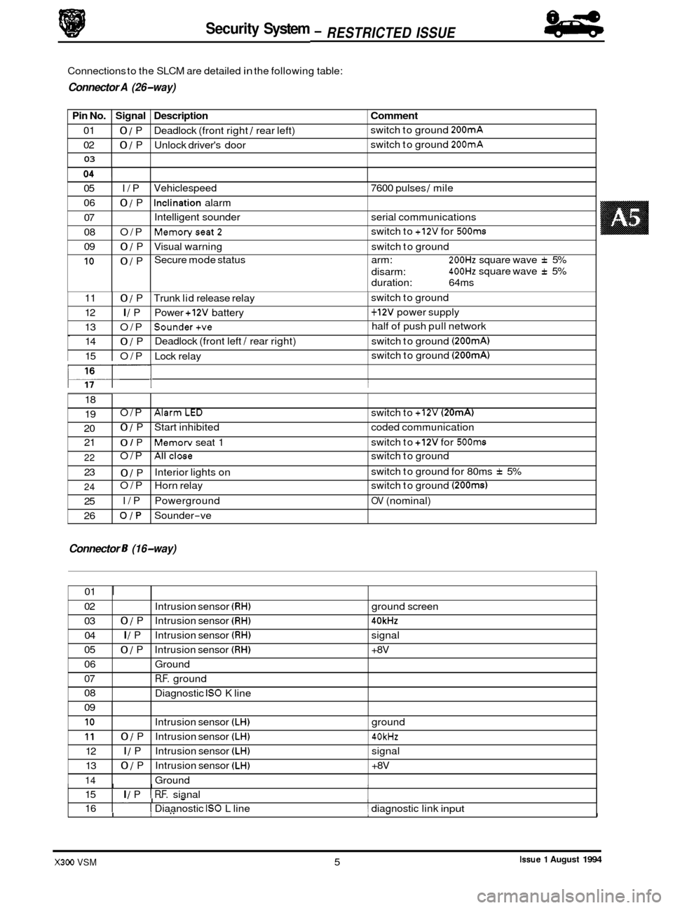
Connections to the SLCM are detailed in the following table:
9 Connector A (26-way)
Comment
switch to ground 200mA
switch to ground 200mA
05 I/P
06
0 / P
07
08 O/P
09
0 / P
10 0 / P Vehiclespeed
7600 pulses
/ mile
Inclination alarm
Intelligent sounder serial communications
Memoryseat2
Visual warning switch to ground
Secure mode status arm:
200Hz square wave f 5%
400Hz square wave f 5%
switch
to
+12V for 500ms
disarm:
duration: 64ms
0
117- I I
11 0 / P Trunk lid release relay 1 switch to ground
12
I / P Power +12V battery 1 + 12V power supply
13 O/P
Sounder+ve half of push pull network
14
0 / P Deadlock
(front left / rear right) switch to ground (200mA)
15 O/P Lock relay switch
to ground (200mA)
18
19
20 21 O/P
AlarmLED switch
to +12V (20mA)
0 / P Start inhibited coded communication
0 / P Memorv seat 1 switch
to +12V for 500ms
Connector 8 (16-way)
22
23
24
25
26 O/P
Allclose switch
to ground
0 / P
O/P Horn relay switch to ground
(200ms)
I/P Powerground OV (nominal)
OJP Sounder-ve
Interior lights
on switch
to ground for 80ms
f 5%
01
I
02
03 04
05
06
07
08
09
I I I I 15 I I / P I R.F. sianal
Intrusion
sensor
(RH) ground screen
0 / P Intrusion sensor (RH) 40kHz
I / P Intrusion sensor (RH) signal
0 / P Intrusion sensor (RH) +8V
Ground
R.F. ground
Diagnostic
IS0 K line
I. I - I 16 I I Diaanostic IS0 L line 1 diagnostic link input
10
11
12
13
14
.I
I I" 1- I
Intrusion sensor (LH) ground
0 / P Intrusion sensor (LH) 40kHz
I / P Intrusion sensor (LH) signal
0 / P Intrusion sensor (LH) +8V
Ground
Issue 1 August 1994 X300 VSM 5
84
- RESTRICTED ISSUE -
Page 485 of 521
Security System - RESTRICTED ISSUE 8-8
-
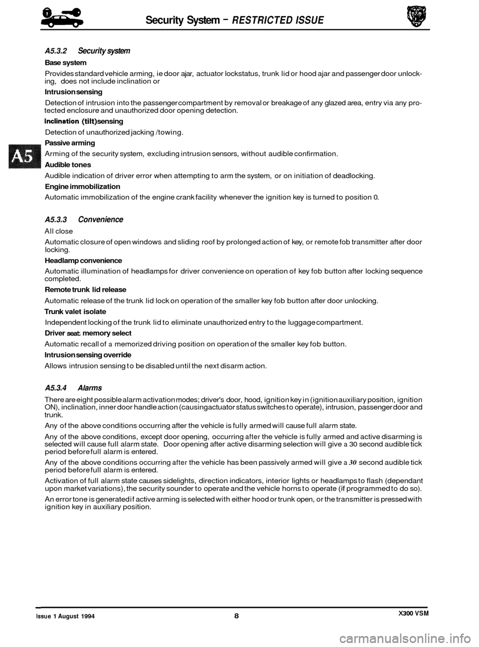
A5.3.2 Security system
Base system
Provides standard vehicle arming, ie door ajar, actuator lockstatus, trunk lid or hood ajar and passenger door unlock- ing, does not include inclination or
Intrusion sensing
Detection of intrusion into the passenger compartment by removal or breakage of any glazed area, entry via any pro- tected enclosure and unauthorized door opening detection.
Inclination (tilt) sensing
Detection of unauthorized jacking /towing.
Passive arming
Arming of the security system, excluding intrusion sensors, without audible confirmation.
Audible tones
Audible indication of driver error when attempting to arm the system, or on initiation of deadlocking.
Engine immobilization
Automatic immobilization of the engine crank facility whenever the ignition key is turned to position 0.
A5.3.3 Convenience
All close
Automatic closure of open windows and sliding roof by prolonged action of key, or remote fob transmitter after door
locking.
Headlamp convenience
Automatic illumination of headlamps for driver convenience on operation of key fob button after locking sequence
completed.
Remote trunk lid release
Automatic release of the trunk lid lock on operation of the smaller key fob button after door unlocking.
Trunk valet isolate
Independent locking of the trunk lid to eliminate unauthorized entry to the luggage compartment.
Driver seat memory select
Automatic recall of a memorized driving position on operation of the smaller key fob button.
Intrusion sensing override
Allows intrusion sensing to be disabled until the next disarm action.
A5.3.4 Alarms
There are eight possible alarm activation modes; driver's door, hood, ignition key in (ignition auxiliary position, ignition ON), inclination, inner door handle action (causing actuator status switches to operate), intrusion, passenger door and
trunk.
Any of the above conditions occurring after the vehicle is fully armed will cause full alarm state.
Any of the above conditions, except door opening, occurring
after the vehicle is fully armed and active disarming is
selected will cause full alarm state. Door opening after active disarming selection will give a 30 second audible tick
period before full alarm is entered.
Any of the above conditions occurring
after the vehicle has been passively armed will give a 30 second audible tick
period before full alarm is entered.
Activation of full alarm state causes sidelights, direction indicators, interior lights or headlamps to flash (dependant
upon market variations), the security sounder to operate and the vehicle horns to operate
(if programmed to do so).
An error tone is generated if active arming is selected with either hood or trunk open, or the transmitter is pressed with
ignition key in auxiliary position.
0
X300 VSM Issue 1 August 1994 8
Page 491 of 521
Security System - RESTRlCTED /SUE 84
-
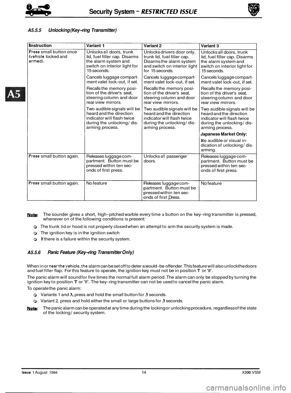
A5.5.5 Unlocking (Key-ring Transmitter)
Instruction
'ress small button once
Ivehicle locked and armed).
'ress small button again.
>ress small button again.
Variant 1
Unlocks all doors, trunk
lid, fuel filler cap. Disarms
the alarm system and
switch on interior light for
15 seconds.
Cancels luggage compart
-
ment valet lock-out, if set.
Recalls the memory posi
- tion of the driver's seat,
steering column and door
rear view mirrors.
Two audible signals will be
heard and the direction
indicator will flash twice
during the unlocking
/ dis- arming process.
Releases luggage com
- partment. Button must be
pressed within ten sec
- onds of first press.
No feature
Variant 2
Unlocks drivers door only,
trunk lid, fuel filler cap.
Disarms the alarm system
and switch on interior light
for 15 seconds.
Cancels luggage compart
-
ment valet lock-out, if set.
Recalls the memory posi
- tion of the driver's seat,
steering column and door
rear view mirrors.
Two audible signals will be
heard and the direction
indicator will flash twice
during the unlocking
/ dis-
arming process.
Unlocks
all passenger
doors.
Releases luggage com
-
partment. Button must be
pressed within ten sec
- onds of first Dress.
Variant 3
Unlocks all doors, trunk
lid, fuel filler cap. Disarms
the alarm system and
switch on interior light for
15 seconds.
Cancels luggage compart
-
ment valet lock-out, if set.
Recalls the memory posi
- tion of the driver's seat,
steering column and door
rear view mirrors.
Two audible signals will be
heard and the direction
indicator will flash twice
during the unlocking
/ dis-
arming process.
Japanese Market Only:
No audible or visual in-
dication of unlocking / dis- arming.
Releases luggage com
-
partment. Button must be
pressed within ten sec-
onds of first press.
No feature
M&:
o The trunk lid or hood is not properly closed when an attempt to arm the security system is made.
0 The ignition key is in the ignition switch
0 If there is a failure within the security system.
The
sounder gives
a short, high-pitched warble every time a button on the key-ring transmitter is pressed,
whenever on of the following conditions is present:
A5.5.6 Panic Feature (Key-ring Transmitter Only)
When in or nearthe vehicle,the alarm can be set off to deter a would-be offender. This feature will also unlockthe doors
and fuel filler flap. For this feature to operate, the ignition key must not be in position 'I' or '11'.
The panic alarm will sound for five times the normal full alarm period. The alarm can only be stopped by turning the
ignition key to position 'I' or '11'. The key-ring transmitter can not be used to cancel the panic alarm.
To operate the panic alarm:
0 Variants 1 and 3, press and hold the small button for 3 seconds.
o Variant 2, press and hold either the small or large buttons for 3 seconds.
MzW The panic alarm can be operated at any time during the locking or unlocking procedure, regardless of the state
of the locking / security system.
Issue 1 August 1994 14 X300 VSM
Page 496 of 521

A5.7.5 Unlocking (Key-ring Transmitter)
G
nstruction
'ress small button once
vehicle locked and
armed).
Press small button again
Press small button again
Variant 1 I Variant 2 I Variant 3
Check all doors, trunk lid and fuel filler cap unlock Check that the alarm system dis- arms and the interior light illuminates for 15 seconds.
Check luggage compartment valet
lock-out is cancelled, if set.
Ensure the memory position of the driver's seat, steering column and door rear view
mirrors is restored.
Check that two audible signals are heard and the direction indicator flashes twice
during the unlocking
/ disarmina process.
Check luggage compart
- ment released when but-
ton pressed within ten sec- onds of first press.
No feature
-.
Japanese Market Only:
No
audible or visual in-
dication of unlocking / dis-
arming.
Check
all passenger doors Check luggage compart- unlocked. ment released when but-
ton pressed within 10 sec- onds of first press.
Check luggage compart
- No feature.
ment released when but
- ton pressed within 10 sec-
onds of second press.