coolant level JAGUAR XJ6 1994 2.G Workshop Manual
[x] Cancel search | Manufacturer: JAGUAR, Model Year: 1994, Model line: XJ6, Model: JAGUAR XJ6 1994 2.GPages: 521, PDF Size: 17.35 MB
Page 12 of 521
Introduction
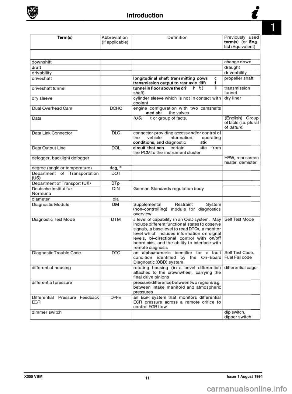
Term(s) Abbreviation Definition
(if applicable) Previously
used term(s) (or Eng-
lish Equivalent)
downshift
draft _.
drivability
driveshaft
driveshaft tunnel
dry sleeve
Dual Overhead Cam
Data
Data Link Connector
Data Output Line
defogger, backlight defogger
degree (angle or temperature)
Department of Transportation
(US)
Department of Transport (UK)
Deutsche lnstitut fur
Normuna
diameter
Diagnostic Module
Diagnostic Test Mode
Diagnostic Trouble Code
differential housing
differentia
I pressure
Differential Pressure Feedback
EGR
dimmer switch DOHC
DLC
DOL
deg, O
DOT
DTP DIN dia
DM
DTM
DTC
DPFE longitudinal
shaft transmitting power from
transmission output to rear axle differential
tunnel
in floor above the driveshaft (propeller
shaft)
cylinder sleeve which is not in contact with
coolant
engine configuration with two camshafts
positioned above the valves
(US) Fact or group of facts.
connector providing access
andlor control of
the vehicle information, operating
conditions, and diagnostic information
circuit that sends certain information from
the PCM to the instrument cluster
German Standards regulation body
Supplemental Restraint System
(non-controlling) module for diagnostics
overview
a level of capability in an OBD system. May
include different functional states
to observe
signals, a base level to read
DTCs, a monitor
level which includes information on signal
levels,
bi-directional control with onloff board aids, and the ability to interface with
remote diagnosis
an
alphahumeric identifier for a fault
condition identified by the On
-Board
Diagnostic
(OBD) system
rotating housing
(in a bevel differential)
attached to the crownwheel, carrying the
final drive pinions
pressure difference between two regions e.g.
between intake manifold and atmospheric
pressures
an EGR system that monitors differential
EGR pressure across a remote orifice
to control EGR flow change
down
draught
driveability
propeller shaft
transmission
tunnel
dry liner
(English) Group
of facts (i.e. plural
of
datum)
HRW, rear screen
heater, demister
Self Test Mode
Self Test Code.
Fuel Fail code
differential cage
dip switch,
dipper switch
Issue 1 August 1994 11 X300 VSM
Page 14 of 521
Introduction c
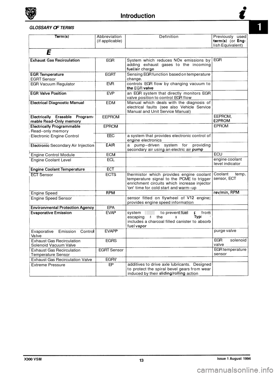
GLOSSARY OF TERMS
Term(s) Abbreviation Definition Previously used (if applicable) term(s) (or Eng- lish Equivalent)
0
EGRT Sensor
EGR Vacuum Regulator
1 Read-only memory
I Electronic Engine Control
kronic Secondary Air Injection
Engine Control Module
Engine Coolant Level
ECT Sensor
Engine Speed
Engine Speed Sensor
1 Evaporative Emission Control
Va Ive
Exhaust Gas Recirculation
Solenoid Vacuum Valve
Exhaust Gas Recirculation
Temperature Sensor
Exhaust Gas Recirculation Valve
Extreme Pressure EGR
EGRT EVR
EVP
EDM
EEPROM EPROM EEC
EAlR
ECM ECL
ECT
ECTS
RPM
EPA
EVAP
EVAPP EGRS
EGRT Sensor
EGRV EP System
which reduces
NOx emissions by
adding exhaust gases to the incoming
fuel/air charae
Sensing EGR function based on temperature
change.
controls EGR flow by changing vacuum to
the EGR valve
an EGR system that directly monitors EGR
valve position to control EGR flow
Manual which deals with the diagnosis of
electrical faults (see also Vehicle Service
Manual and Unit Service Manual)
a system that provides electronic control of
enaine electronics
a pump
-driven system for providing
secondarv air usina an electric air Dump
thermistor which provides engine coolant
temperature signal to the PCME to trigger
enrichment circuits which increase injector
'on' time for cold start and warm-up
sensor fitted on flywheel of
VI2 engine;
provides engine speed information
system designed to prevent fuel vapor from
escaping into the atmosphere. Typically
includes a charcoal filled canister to absorb
fuel
vaoor
additives to drive axle lubricants. Designed
to protect the spiral bevel gears from wear
induced by their
slidingholling action EGR
EEPROM,
EPPROM
EPROM ECU
engine coolant level indicator
Coolant temp.
sensor, ECT
revlmin. RPM
purge valve
EGR solenoid
valve
EGR temperature
sensor
X300 VSM issue 1 August 1994 13
Page 56 of 521
Cooling System (AJl6) m
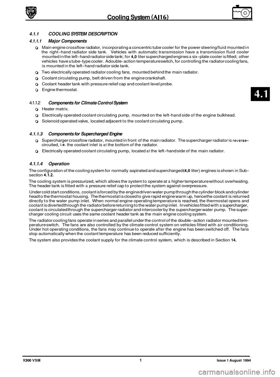
4.1.1 COOLING SYSTEM DESCRIPTION
4.1.1.1 Major Components
o Main engine crossflow radiator, incorporating a concentric tube cooler for the power steering fluid mounted in
the right
-hand radiator side tank. Vehicles with automatic transmission have a transmission fluid cooler
mounted in the left
-hand radiator side tank; for 4,O liter supercharged engines a six-plate cooler is fitted; other
vehicles have
a tube-type cooler. Adouble-action temperature switch, for controlling the radiator cooling fans,
is mounted in the left
-hand radiator side tank.
0 Two electrically operated radiator cooling fans, mounted behind the main radiator.
0 Coolant circulating pump, belt driven from the engine crankshaft.
0 Coolant header tank with pressure relief cap and coolant level probe.
o Engine thermostat.
4.1.1.2
0 Heater matrix.
o Electrically operated coolant circulating pump, mounted on the left-hand side of the engine bulkhead.
o Solenoid operated valve, located adjacent to the coolant circulating pump.
Components for Climate Control System
4.1.1.3 Components for Supercharged Engine
0 0 Supercharger crossflow radiator, mounted in front of the main radiator. The supercharger radiator is reverse- circuited, i.e. the coolant inlet is at the bottom of the radiator.
0 Electrically operated coolant circulating pump, located at the left-hand side of the main radiator.
4.1.1.4 Operation
The configuration of the cooling system for normally aspirated and supercharged (4,O liter) engines is shown in Sub- section 4.1.2.
The cooling system is pressurized, which allows the system to operate at a higher temperature without overheating.
The header tank is fitted with a pressure relief cap to protect the system against overpressure.
Under cold start conditions, coolant is forced by the engine driven water pump through the cylinder block and cylinder
head to the thermostat housing. The thermostat is closed to give rapid engine warm up, hence the coolant is returned
directly to the water pump inlet. When normal engine operating temperature is reached, the thermostat opens and
coolant is diverted through the radiator before returning to the water pump inlet. In vehicles fitted with
a supercharger,
coolant is circulated through the supercharger radiator and intercooler by the supercharger water pump. The super- charger cooling circuit uses the same coolant header tank as the main engine cooling system.
The radiator cooling fans operate in series and parallel under the control of the double
-action radiator mounted tem- perature switch. The fans are also controlled by the climate control system on vehicles fitted with air conditioning.
Under hot operating conditions, the fans may continue to operate after the engine has been switched off. The fans
stop automatically when the coolant temperature has been reduced sufficiently.
The system also provides the coolant supply for the climate control system, which is described in Section
14.
X300 VSM 1 Issue 1 August 1994
Page 58 of 521
area washed to remove all traces of coolant.
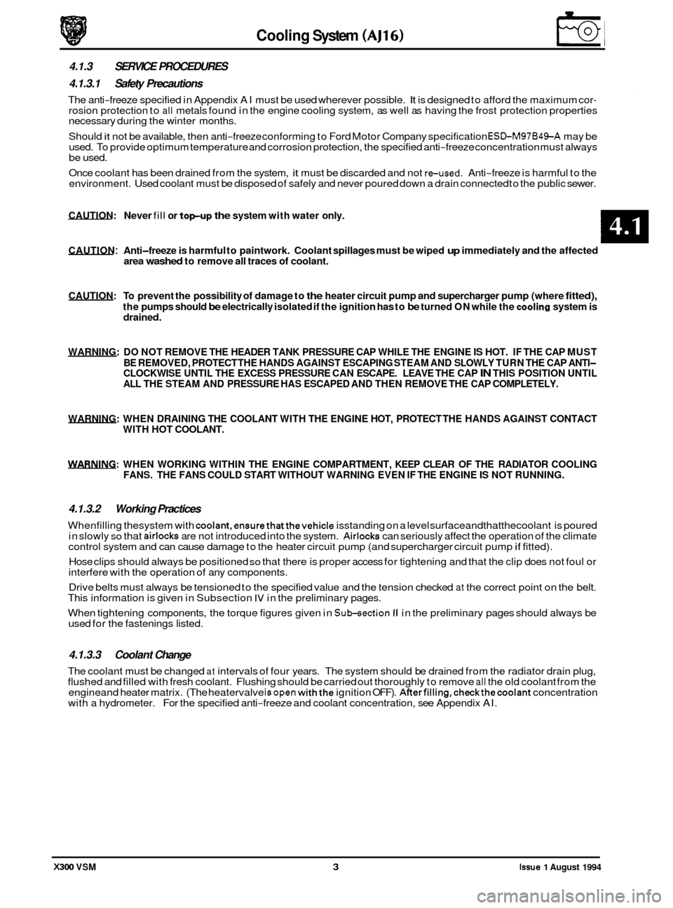
CAUTION: To prevent the possibility of damage to the heater circuit pump and supercharger pump (where fitted),
the pumps should be electrically isolated if the ignition has to be turned ON while the cooling system is
drained.
WARNING: DO NOT REMOVE THE HEADER TANK PRESSURE CAP WHILE THE ENGINE IS HOT. IF THE CAP MUST
BE REMOVED, PROTECT THE HANDS AGAINST ESCAPING STEAM AND SLOWLY TURN THE CAP ANTI
- CLOCKWISE UNTIL THE EXCESS PRESSURE CAN ESCAPE. LEAVE THE CAP IN THIS POSITION UNTIL
ALL THE STEAM AND PRESSURE HAS ESCAPED AND THEN REMOVE THE CAP COMPLETELY.
WARNING: WHEN DRAINING THE COOLANT WITH THE ENGINE HOT, PROTECT THE HANDS AGAINST CONTACT
WITH HOT COOLANT.
WARNING: WHEN WORKING WITHIN THE ENGINE COMPARTMENT, KEEP CLEAR OF THE RADIATOR COOLING
FANS. THE FANS COULD START WITHOUT WARNING EVEN IF THE ENGINE IS NOT RUNNING.
4.1.3.2 Working Practices
Whenfilling thesystem with coolant,ensurethatthevehicle isstanding on a level surfaceandthatthecoolant is poured
in slowly so that airlocks are not introduced into the system. Airlocks can seriously affect the operation of the climate
control system and can cause damage to the heater circuit pump (and supercharger circuit pump if fitted).
Cooling System (AJ16)
4.1.3 SERVICE PROCEDURES
4.1.3.1 Safety Precautions
The anti-freeze specified in Appendix AI must be used wherever possible. It is designed to afford the maximum cor- rosion protection to all metals found in the engine cooling system, as well as having the frost protection properties
necessary during the winter months.
Should
it not be available, then anti-freeze conforming to Ford Motor Company specification ESLbM97B49-A may be
used. To provide optimum temperature and corrosion protection, the specified anti-freeze concentration must always
be used.
Once coolant has been drained from the system,
it must be discarded and not reused. Anti-freeze is harmful to the
environment. Used coolant must be disposed of safely and never poured down a drain connected to the public sewer.
CAUTION: Never fill or topup the system with water only.
CAUTION : Anti-freeze is harmful to paintwork. Coolant spillages must be wiped up immediately and the affected
Hose clips should always be positioned so that there is proper access for tightening and that the clip does not foul or
interfere with the operation of any components.
Drive belts must always be tensioned to the specified value and the tension checked
at the correct point on the belt.
This information is given in Subsection IV in the preliminary pages.
0
When tightening components, the torque figures given in Sukection II in the preliminary pages should always be
used for the fastenings listed.
4.1.3.3 Coolant Change
The coolant must be changed at intervals of four years. The system should be drained from the radiator drain plug,
flushed and filled with fresh coolant. Flushing should be carried out thoroughly to remove all the old coolant from the
engineand heater matrix. (The heatervalve isopen withthe ignition OFF). AfterfiIling,checkthecoolant concentration
with a hydrometer. For the specified anti-freeze and coolant concentration, see Appendix AI.
X300 VSM 3 Issue 1 August 1994
Page 59 of 521
€3 Cooling System (AJ16)
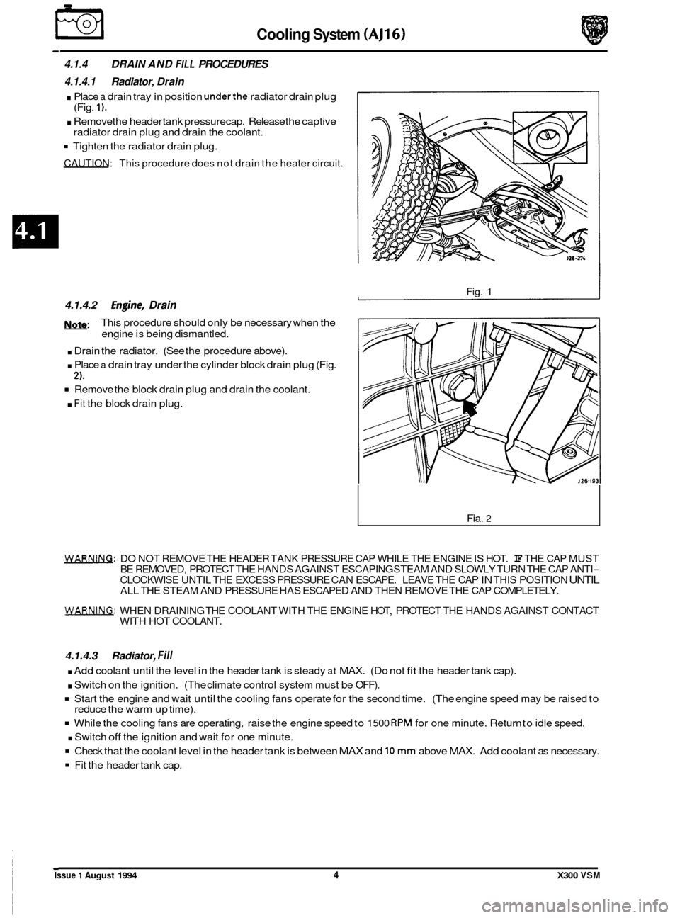
4.1.4 DRAIN AND FILL PROCEDURES
4.1.4.1 Radiator, Drain
. Place a drain tray in position underthe radiator drain plug
. Remove the header tank pressure cap. Release the captive
Tighten the radiator drain plug.
CAUTION: This procedure does not drain the heater circuit.
(Fig. 1).
radiator drain plug and drain the coolant.
4.1.4.2 Engh-, Drain
m:
. Drain the radiator. (See the procedure above).
. Place a drain tray under the cylinder block drain plug (Fig.
Remove the block drain plug and drain the coolant.
. Fit the block drain plug.
This procedure
should only be necessary when the
engine is being dismantled.
2).
Fig. 1
Fia. 2
WAm. DO NOT REMOVE THE HEADER TANK PRESSURE CAP WHILE THE ENGINE IS HOT. IF THE CAP MUST
BE REMOVED, PROTECT THE HANDS AGAINST ESCAPING STEAM AND SLOWLY TURN THE CAP ANTI- CLOCKWISE UNTIL THE EXCESS PRESSURE CAN ESCAPE. LEAVE THE CAP IN THIS POSITION UNTIL ALL THE STEAM AND PRESSURE HAS ESCAPED AND THEN REMOVE THE CAP COMPLETELY.
WARNING: WHEN DRAINING THE COOLANT WITH THE ENGINE HOT, PROTECT THE HANDS AGAINST CONTACT
WITH HOT COOLANT.
4.1.4.3 Radiator, Fill
. Add coolant until the level in the header tank is steady at MAX. (Do not fit the header tank cap).
. Switch on the ignition. (The climate control system must be OFF).
Start the engine and wait until the cooling fans operate for the second time. (The engine speed may be raised to
While the cooling fans are operating, raise the engine speed to 1500 RPM for one minute. Return to idle speed.
. Switch off the ignition and wait for one minute.
Check that the coolant level in the header tank is between MAX and 10 mm above MAX. Add coolant as necessary.
Fit the header tank cap.
reduce
the warm up time).
Issue 1 August 1994 4 X300 VSM
Page 60 of 521
.
0
0
Cooling System (AJ1
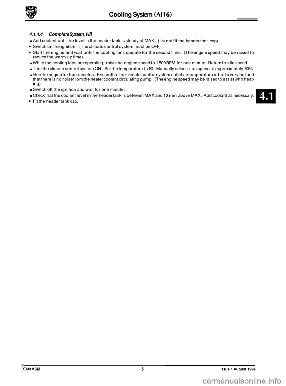
4.1.4.4 Complete System, Fill
. Add coolant until the level in the header tank is steady at MAX. (Do not fit the header tank cap).
m Switch on the ignition. (The climate control system must be OFF).
Start the engine and wait until the cooling fans operate for the second time. (The engine speed may be raised to
. While the cooling fans are operating, raise the engine speed to 1500 RPM for one minute. Return to idle speed.
. Turn the climate control system ON. Set the temperature to HI. Manually select a fan speed of approximately 50%.
. Run the engine for four minutes. Ensure that the climate control system outlet airtemperature is hot to very hot and
that there is no noise from the heater coolant circulating pump. (The engine speed may be raised to assist with heat- ing).
reduce the warm up time).
. Switch off the ignition and wait for one minute.
. Check that the coolant level in the header tank is between MAX and 10 mm above MAX. Add coolant as necessary.
Fit the header tank cap.
X300 VSM 5 Issue 1 August 1994
Page 61 of 521
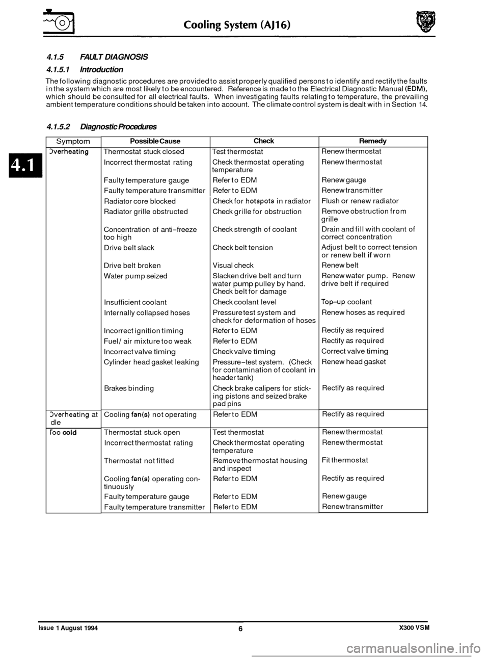
4.1.5 FAULT DIAGNOSIS
4.1.5.1 Introduction
The following diagnostic procedures are provided to assist properly qualified persons to identify and rectify the faults
in the system which are most likely to be encountered. Reference is made to the Electrical Diagnostic Manual (EDM),
which should be consulted for all electrical faults. When investigating faults relating to temperature, the prevailing
ambient temperature conditions should be taken into account. The climate control system is dealt with in Section 14.
Possible Cause
Thermostat stuck closed
Incorrect thermostat rating
Faulty temperature gauge
Faulty temperature transmitter
4.1.5.2 Diagnostic Procedures
Check
Test thermostat
Check thermostat operating
temperature
Refer to EDM
Refer to EDM
Symptom
herheating
Cooling fan(s) not operating 3verheating at
dle
roo cold
Refer to EDM
Incorrect thermostat rating
Thermostat not fitted
Cooling
fan(s) operating con-
tinuously Faulty temperature gauge
Faulty temperature transmitter
Radiator
core blocked
Radiator grille obstructed
Check thermostat operating
temperature
Remove thermostat housing
and inspect
Refer to EDM
Refer to EDM
Refer to EDM
Concentration of
anti
-freeze too high
Drive belt slack
Drive belt broken
Water pump seized
Insufficient coolant
Internally collapsed hoses
Incorrect ignition timing
Fuel
/ air mixture too weak
Incorrect valve
timing
Cylinder head gasket leaking
Brakes binding Check
for
hotspots in radiator
Check grille for obstruction
Check strength of coolant
Check belt tension
Visual check
Slacken drive belt and turn
water
pump pulley by hand.
Check belt for damage
Check coolant level
Pressure test system and
check for deformation of hoses
Refer to EDM
Refer to EDM
Check valve
timing
Pressure-test system. (Check
for contamination of coolant
in header tank)
Check brake calipers for stick
-
ing pistons and seized brake
pad pins
Thermostat stuck open
I Test thermostat
Remedy
Renew thermostat
Renew thermostat
Renew gauge
Renew transmitter
Flush
or renew radiator
Remove obstruction from
grille
Drain and fill
with coolant of
correct concentration
Adjust belt to correct tension
or renew belt
if worn
Renew belt
Renew water pump. Renew
drive belt
if required
Top-up coolant
Renew hoses as required
Rectify
as required
Rectify
as required
Correct valve
timing
Renew head gasket
Rectify
as required
Rectify
as required
Renew thermostat
Renew thermostat
Fit thermostat
Rectify
as required
Renew gauge
Renew transmitter
0
e
0
0
Issue 1 August 1994 X300 VSM
Page 66 of 521
Cooling System (V12
4.2.1 COOLING SYSTEM DESCRIPTION I
4.2.1.1 Major Components
o Engine crossflow radiator, incorporating a concentric tube cooler for the power steering fluid mounted in the
left
-hand radiator side tank. Vehicles with automatic transmission have a six-plate transmission fluid cooler
mounted in the right
-hand radiator side tank. A double-action temperature switch, for controlling the electric
radiator cooling fans, is mounted in the left
-hand radiator side tank.
0 Engine driven, viscous-coupled, radiator cooling fan
0 Two electrically operated radiator cooling fans, mounted in front of the radiator.
o Coolant circulating pump, belt driven from the engine crankshaft.
0 Coolant header tank with pressure relief cap and coolant level probe.
0 Two engine thermostats, one in each cylinder bank.
4.2.1.2
0 Heater matrix.
0 Electrically operated coolant circulating pump, mounted on the left-hand side of the engine bulkhead.
o Solenoid operated valve, located adjacent to the coolant circulating pump.
Components for Climate Control System
1
4.2.1.3 Operation
The configuration of the cooling system is shown in Sub-section 4.2.2.
The cooling system is pressurized, which allows the system to operate at a higher temperature without overheating.
The header tank is fitted with a pressure relief cap to protect the system against overpressure.
Under cold start conditions, coolant is forced by the engine driven water pump through each cylinder block and cylin
- der head to the thermostat housings. The thermostats are closed to give rapid engine warm up, hence the coolant is
returned via the engine cross pipe to the water pump inlet. When normal engine operating temperature is reached,
the thermostats open and coolant is diverted through the radiator before returning to the water pump inlet.
If the engine driven fan is unable to provide sufficient cooling, the electrically operated fans operate in series and paral
-
lel underthe control of the radiator mounted temperature switch. Under hot operating conditions, the electric fans may
continue to operate after the engine has been switched off. The fans stop automatically when the coolant temperature
has been reduced sufficiently.
The system also provides the coolant supply for the climate control system, which is described in Section 14.
I
I X300 VSM 1 Issue 1 August 1994
Page 68 of 521
WARNING: DO NOT REMOVE THE HEADER TANK PRESSURE CAP WHILE THE ENGINE IS HOT. IF THE CAP MUST
BE REMOVED, PROTECT THE HANDS AGAINST ESCAPING STEAM AND SLOWLY TURN THE CAP ANTI- CLOCKWISE UNTIL THE EXCESS PRESSURE CAN ESCAPE. LEAVE THE CAP IN THIS POSITION UNTIL
ALL THE STEAM AND PRESSURE HAS ESCAPED AND THEN REMOVE THE CAP COMPLETELY.
WARNING: WHEN DRAINING THE COOLANT WITH THE ENGINE HOT, PROTECT THE HANDS AGAINST CONTACT
WITH HOT COOLANT.
WARNING
: WHEN WORKING WITHIN THE ENGINE COMPARTMENT, KEEP CLEAR OF THE ENGINE DRIVEN RADI- ATOR COOLING FAN WHEN THE ENGINE IS RUNNING.
4.2.3.2 Working Practices
Whenfilling thesystem with coolant,ensurethatthevehicle isstanding on a level surfaceand thatthecoolant is poured
in slowly so that airlocks are not introduced into the system. Airlocks can seriously affect the operation of the climate
control system and can cause damage to the heater circuit pump.
Hose clips should always be positioned
so that there is proper access for tightening and that the clip does not foul or
interfere with the operation of any components.
4.2.3 SERVICE PROCEDURES
4.2.3.1 Safety Precautions
The anti-freeze specified in Appendix A1 must be used wherever possible. It is designed to afford the maximum cor- rosion protection to all metals found in the engine cooling system, as well as having the frost protection properties
necessary during the winter months. Should it not be available, then anti-freeze conforming to Ford Motor Company
specification
ESBM97B49-A may be used. To provide optimum temperature and corrosion protection, the specified
anti-freeze concentration must always be used. Once coolant has been drained from the system, it must be discarded
and not reused. Anti-freeze is harmful to the environment. Always dispose of used coolant safely and never pour it down a drain connected to the public sewer.
CAUTION: Never fill or topup the system with water only.
CAUTION
: Anti-freeze is harmful to paintwork. Coolant spillages must be wiped up immediately and the affected
area washed to remove all traces of coolant.
CAUTION: To prevent the possibility of damage to the heater circuit
pump, the pump should be electrically isolated if the ignition has to be turned ON while the cooling system is drained.
The drive belt must always be tensioned to the specified value and the tension checked at the correct point on the belt.
This information is given in Sub-section IV in the preliminary pages.
When tightening components, the torque figures given in Sub
-section II in the preliminary pages should always be
used for the fastenings listed.
When fitting a replacement thermostat, ensure that the jiggle-pin is to the top of the thermostat housing.
4.2.3.3 Coolant Change
The coolant must be changed at intervals of four years. The system should be drained from the radiator drain plug,
flushed and filled with fresh coolant. Flushing should be carried out thoroughly to remove all the old coolant from the
engine and heater matrix. (The heatervalve isopen with the ignition OFF). AfterfilIing,checkthecoolant concentration
with a hydrometer. For specified anti-freeze and coolant concentration, see in Appendix Al.
X300 VSM 3 Issue 1 August 1994
Page 69 of 521
€3 Cooling System (V12)
4.2.4 DRAIN AND FILL PROCEDURES
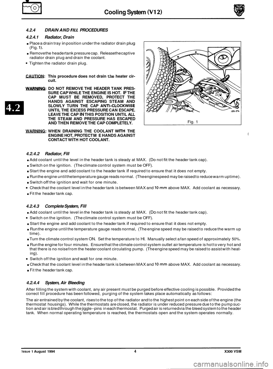
4.2.4.1 Radiator, Drain
. Place a drain tray in position under the radiator drain plug
. Remove the headertank pressure cap. Release thecaptive
Tighten the radiator drain plug.
(Fig.
1).
radiator drain
plug and drain the coolant.
CAUTION: This procedure does not drain the heater cir- cuit.
m: DO NOT REMOVE THE HEADER TANK PRES- SURE CAP WHILE THE ENGINE IS HOT. IF THE
CAP MUST BE REMOVED, PROTECT THE
HANDS AGAINST ESCAPING STEAM AND
SLOWLY TURN THE CAP
ANTI-CLOCKWISE UNTIL THE EXCESS PRESSURE CAN ESCAPE.
LEAVE THE CAP IN THIS POSITION UNTIL ALL
THE STEAM AND PRESSURE HAS ESCAPED
AND THEN REMOVE THE CAP COMPLETELY.
WARNING: WHEN DRAINING THE COOLANT
WITH THE
ENGINE HOT, PROTECT ME HANDS AGAINST
CONTACT WITH HOT COOLANT.
Fig. 1
4.2.4.2 Radiator, Fill
. Add coolant until the level in the header tank is steady at MAX. (Do not fit the header tank cap).
. Switch on the ignition. (The climate control system must be OFF).
. Start the engine and add coolant to the header tank if required to ensure that it does not empty.
. Run the engine until thetemperature gauge reads normal. (The enginespeed may be raised to reduce warm uptime).
. Switch off the ignition and wait for one minute.
Check that the coolant level in the header tank is between MAX and
10 mm above MAX. Add coolant as necessary.
. Fit the header tank cap.
4.2.4.3 Complete System, Fill
. Add coolant until the level in the header tank is steady at MAX. (Do not fit the header tank cap).
= Switch on the ignition. (The climate control system must be OFF).
. Start the engine and add coolant to the header tank if required to ensure that it does not empty.
. Run the engine until the temperature gauge reads normal, (The engine speed may be raised to reduce the warm up
. Turn the climate control system ON. Set the temperature to HI. Manually select a fan speed of approximately 50%.
. Run the engine for four minutes. Ensure that the climate control system outlet air temperature is hot to very hot and
that there is no noise from the heater coolant circulating pump. (The engine speed may be raised to assist with heat- ing).
time).
8 Switch
off the ignition and wait for one minute.
. Check that the coolant level in the header tank is between MAX and 10 mm above MAX. Add coolant as necessary.
. Fit the header tank cap.
4.2.4.4 System, Air Bleeding
After filling the system with coolant, any air present must be purged before effective cooling is possible. Provided the
correct fill procedure has been followed, purging of the system takes place automatically as follows:
The air entrained by the coolant, rises to the top of the radiator and to the highest point on each side of the engine (the
thermostat housings). While the thermostats are closed, the radiator is under reduced pressure due to the pump suc
- tion and air is bled through the jiggle-pins in each thermostat. Purged air is returnedvia the bleed system to the header
tank. When normal operating temperature is reached, the thermostats open and the system operates normally. ~~
Issue 1 August 1994 4 X300 VSM