timing belt JAGUAR XJ6 1994 2.G Workshop Manual
[x] Cancel search | Manufacturer: JAGUAR, Model Year: 1994, Model line: XJ6, Model: JAGUAR XJ6 1994 2.GPages: 521, PDF Size: 17.35 MB
Page 39 of 521

Engine (AJ16)
Description
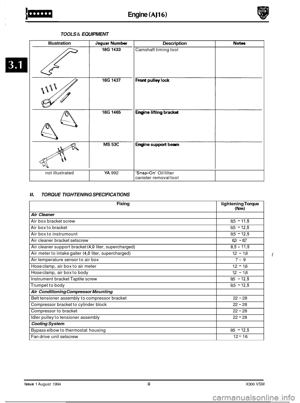
Camshaft timing tool
TOOLS & EQUIPMENT
Not- Illustration I JaguarNumber
L L
11. TORQUE TIGHTENING SPECIFICATIONS
not illustrated YA 992
Fixing
Air Cleaner
Air box bracket screw
Air box to bracket
Air box to instrumount
Air cleaner bracket setscrew
Air cleaner support bracket
(4,O liter, supercharged)
Air meter to intake gaiter
(4,O liter, supercharged)
Air temperature sensor to air box
Hose clamp, air box to air meter
Hose clamp, air box to body
Instrument bracket Taptite screw
Trumpet to body
Air Conditioning Compressor Mounting
Belt tensioner assembly to compressor bracket
Compressor bracket to cylinder block
Compressor to bracket
Idler pulley to tensioner assembly
Cooling System
Bypass elbow to thermostat housing
Fan drive unit setscrew
lightening Torque
(Nm)
8,5 - 11,5
9,5 - 12,5
9,5 - 12,5
6,3 - 8,7
8,5- 11,5
1,2 - 1,6
7
-9
1.2
- 1,6
1,2
- 1,6
9,5
- 12,5
9,5 - 12,5
22 - 28
22
- 28
22
- 28
22
- 28
9.5
- 12,5
12 - 16
Front pulley lock
fi
Engine lifting bracket
fi
Engine support beam
fl
'Snap-On' Oil filter
canister removal tool
Issue 1 August 1994 ii X300 VSM
Page 61 of 521

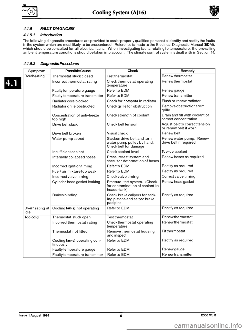
4.1.5 FAULT DIAGNOSIS
4.1.5.1 Introduction
The following diagnostic procedures are provided to assist properly qualified persons to identify and rectify the faults
in the system which are most likely to be encountered. Reference is made to the Electrical Diagnostic Manual (EDM),
which should be consulted for all electrical faults. When investigating faults relating to temperature, the prevailing
ambient temperature conditions should be taken into account. The climate control system is dealt with in Section 14.
Possible Cause
Thermostat stuck closed
Incorrect thermostat rating
Faulty temperature gauge
Faulty temperature transmitter
4.1.5.2 Diagnostic Procedures
Check
Test thermostat
Check thermostat operating
temperature
Refer to EDM
Refer to EDM
Symptom
herheating
Cooling fan(s) not operating 3verheating at
dle
roo cold
Refer to EDM
Incorrect thermostat rating
Thermostat not fitted
Cooling
fan(s) operating con-
tinuously Faulty temperature gauge
Faulty temperature transmitter
Radiator
core blocked
Radiator grille obstructed
Check thermostat operating
temperature
Remove thermostat housing
and inspect
Refer to EDM
Refer to EDM
Refer to EDM
Concentration of
anti
-freeze too high
Drive belt slack
Drive belt broken
Water pump seized
Insufficient coolant
Internally collapsed hoses
Incorrect ignition timing
Fuel
/ air mixture too weak
Incorrect valve
timing
Cylinder head gasket leaking
Brakes binding Check
for
hotspots in radiator
Check grille for obstruction
Check strength of coolant
Check belt tension
Visual check
Slacken drive belt and turn
water
pump pulley by hand.
Check belt for damage
Check coolant level
Pressure test system and
check for deformation of hoses
Refer to EDM
Refer to EDM
Check valve
timing
Pressure-test system. (Check
for contamination of coolant
in header tank)
Check brake calipers for stick
-
ing pistons and seized brake
pad pins
Thermostat stuck open
I Test thermostat
Remedy
Renew thermostat
Renew thermostat
Renew gauge
Renew transmitter
Flush
or renew radiator
Remove obstruction from
grille
Drain and fill
with coolant of
correct concentration
Adjust belt to correct tension
or renew belt
if worn
Renew belt
Renew water pump. Renew
drive belt
if required
Top-up coolant
Renew hoses as required
Rectify
as required
Rectify
as required
Correct valve
timing
Renew head gasket
Rectify
as required
Rectify
as required
Renew thermostat
Renew thermostat
Fit thermostat
Rectify
as required
Renew gauge
Renew transmitter
0
e
0
0
Issue 1 August 1994 X300 VSM
Page 70 of 521

4.2.5.2 Diagnostic Procedures
1
I Symptom ..
Overheating
herheating at
dle
roo cold ~~~
Possible Cause
Thermostat(s) stuck
closed
Incorrect thermostat rating
Faulty temperature gauge
Faulty temperature transmitter
Radiator core blocked
Radiator grille obstructed
Concentration of anti
-freeze
too high
Drive belt slack
Drive belt broken
Water pump seized
lnsuff icient coolant
Internally collapsed hoses
Incorrect ignition timing
Fuel
/ air mixture too weak
Incorrect valve timing
Cylinder head
gasket(s) leak-
ing
Brakes binding
Electric cooling
fan(s) not op- erating
Thermostat(s) stuck open
Incorrect thermostat rating
Thermostatb) not fitted
Electric cooling
fan(s) operat-
ing continuously
Faulty temperature gauge
Faulty temperature transmitter
Check
Cooling System (V12)
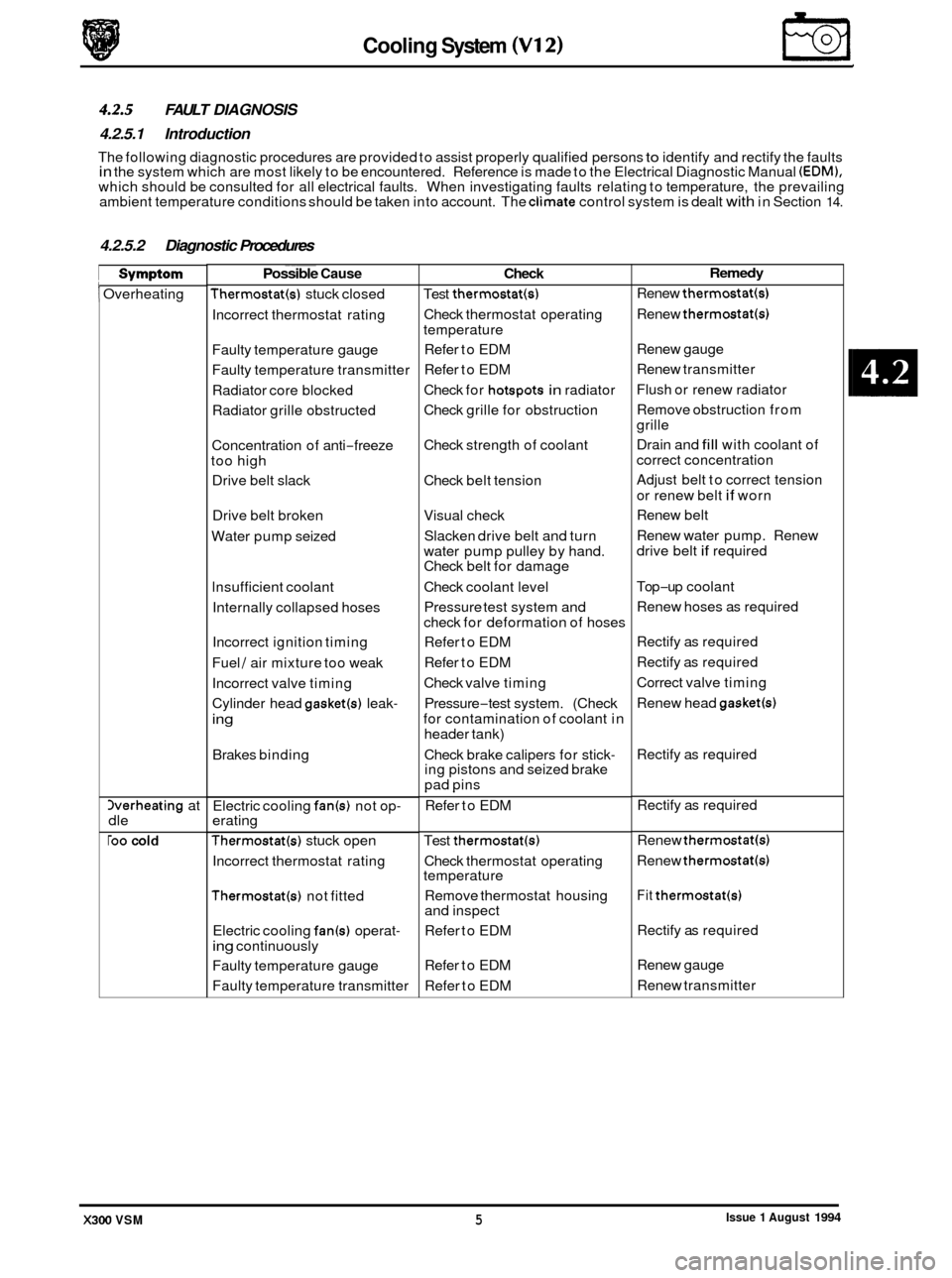
4.2.5 FAULT DIAGNOSIS
4.2.5.1 Introduction
The following diagnostic procedures are provided to assist properly qualified persons to identify and rectify the faults in the system which are most likely to be encountered. Reference is made to the Electrical Diagnostic Manual (EDM), which should be consulted for all electrical faults. When investigating faults relating to temperature, the prevailing
ambient temperature conditions should be taken into account. The climate control system is dealt with in Section 14.
Test thermostat(s)
Check thermostat operating
temperature
Refer to EDM
Refer to EDM
Check for
hotspots in radiator
Check grille for obstruction
Check strength of coolant
Check belt tension
Visual check Slacken drive belt and turn
water pump pulley by hand.
Check belt for damage
Check coolant level
Pressure test system and
check for deformation of hoses
Refer to EDM
Refer to EDM
Check valve timing
Pressure
-test system. (Check
for contamination of coolant in
header tank)
Check brake calipers for stick
- ing pistons and seized brake
pad pins
..
Refer to EDM
Test
thermostat(4
Check thermostat operating
temperature
Remove thermostat housing
and inspect
Refer to EDM
Refer to EDM
Refer to EDM
Remedy
Renew thermostat(s)
Renew thermostat(s1
Renew gauge
Renew transmitter
Flush or renew radiator
Remove obstruction from
grille
Drain and
fill with coolant of
correct concentration
Adjust belt to correct tension
or renew belt
if worn
Renew belt
Renew water pump. Renew
drive belt
if required
Top
-up coolant
Renew hoses as required
Rectify as required
Rectify as required
Correct valve timing
Renew head
gasket(s)
Rectify as required
Rectify as required
Renew
thermostat(s1
Renew thermostatb)
Fit thermostat(s)
Rectify as required
Renew gauge
Renew transmitter
Issue 1 August 1994 X300 VSM 5
Page 201 of 521

@ Steering
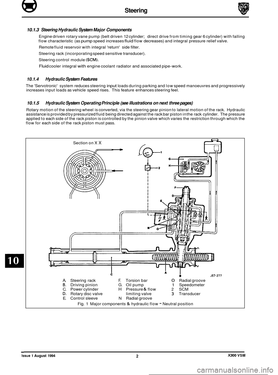
10.1.3 Steering Hydraulic System Major Components
Engine driven rotary vane pump (belt driven 12 cylinder; direct drive from timing gear 6 cylinder) with falling
flow characteristic (as
pump speed increases fluid flow decreases) and integral pressure relief valve.
Remote fluid reservoir with integral 'return' side filter.
Steering rack (incorporating speed sensitive transducer).
Steering control module
(SCM).
Fluid cooler integral with engine coolant radiator and associated pipe-work.
10.1.4 Hydraulic System Features
The 'Servotronic' system reduces steering input loads during parking and low speed manoeuvres and progressively
increases input loads as vehicle speed rises. This feature enhances steering feel.
10.1.5
Rotary motion of the steering wheel is converted, via the steering gear pinion to lateral motion of the rack. Hydraulic
assistance is provided by pressurized fluid being directed against the rack bar piston in the rack cylinder. The pressure
applied to each side of the rack piston is controlled by the pinion valve which varies the restriction through which the
flow for each side of the rack piston must pass.
Hydraulic System Operating Principle (see illustrations on next three pages)
Section on X X
J57-277
A. Steering rack F. Torsion bar 0 Radial groove B. Driving pinion G. Oil pump 1 Speedometer
C. Power cylinder H Pressure & flow 2 SCM D. Rotary disc valve limiting valve 3 Transducer
E. Control sleeve N Radial groove
Fig.
1 Major components & hydraulic flow - Neutral position ~
Issue 1 August 1994 X300 VSM 2