load capacity JAGUAR XJ6 1994 2.G Workshop Manual
[x] Cancel search | Manufacturer: JAGUAR, Model Year: 1994, Model line: XJ6, Model: JAGUAR XJ6 1994 2.GPages: 521, PDF Size: 17.35 MB
Page 32 of 521

0 2.1 JACKING AND LIFTING
2.1.1. Safety Precautions
The following safety precautions must be observed when
raising the vehicle to perform service operations:
0 Whenever possible use a ramp or a pit in preference
to a jack, when working beneath a vehicle.
0 Never rely on a jack to support a vehicle; use axle
stands or blocks under the vehicle jacking points to
provide rigid support.
0 When working beneath a vehicle, chock the wheels in
addition to applying the handbrake.
0 Ensure that the vehicle is standing on firm, level
ground before using the jack
0 Check that any lifting equipment used has adequate
capacity for the load being lifted and is in full working
order.
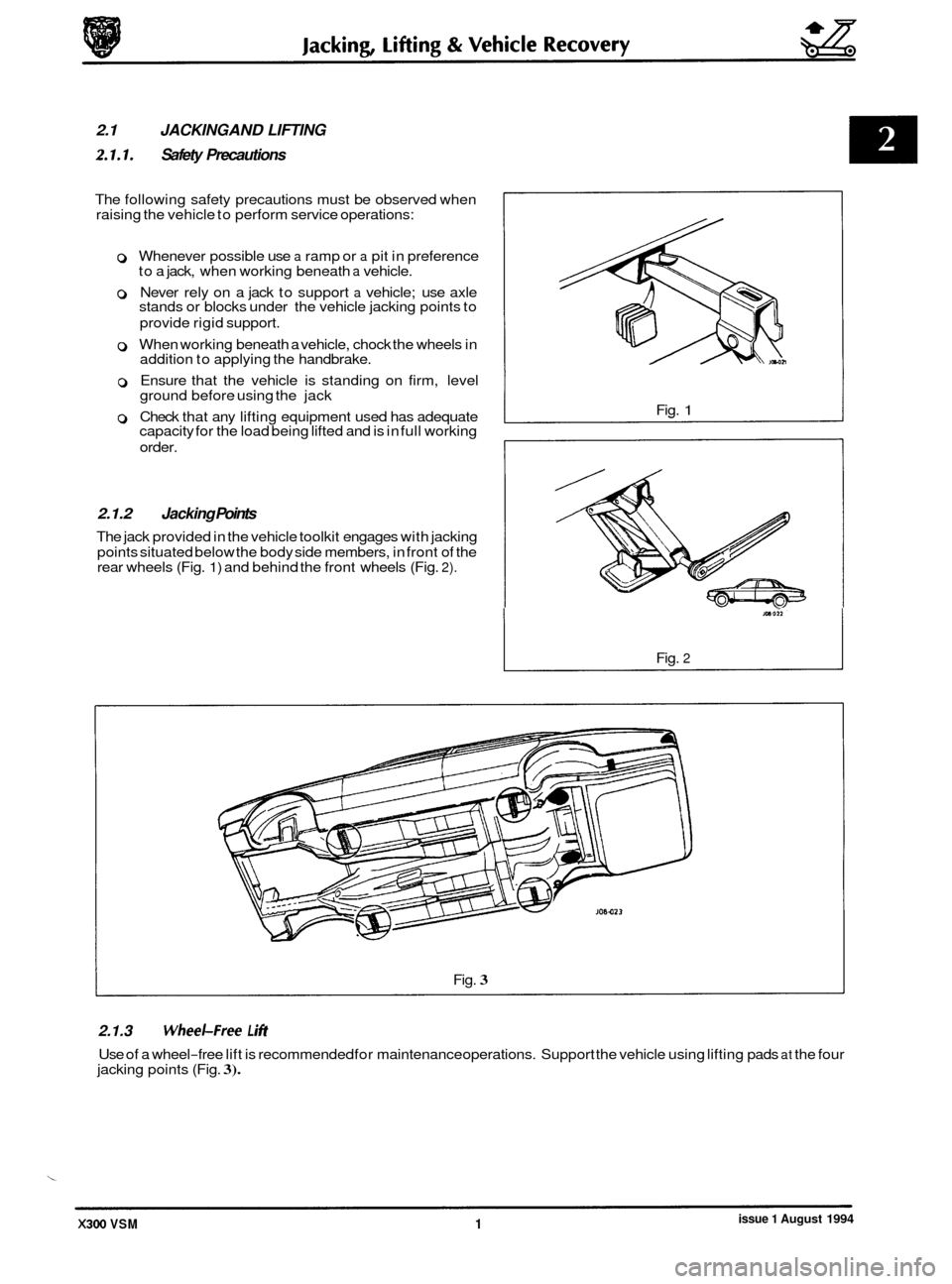
2.1.2 Jacking Points
The jack provided in the vehicle toolkit engages with jacking
points situated below the body side members, in front of the
rear wheels (Fig.
1) and behind the front wheels (Fig. 2).
Fig. 1
Fig. 2
Fig. 3
2.1.3 WheeLFree L i#t
Use of a wheel-free lift is recommended for maintenance operations. Support the vehicle using lifting pads at the four
jacking points (Fig. 3).
issue 1 August 1994 X300 VSM 1
Page 156 of 521

Automatic Transmission (V12 & AJl6 Supercharged) Pomrtrain
8.2.1 GENERAL DESCRIPTION
This section provides information relating to the Powertrain 4L80-E transmissions fitted to the 4,O liter supercharged
engine (4,OL SC) and to the 6,O liter engine (6,OL).
The Powertrain 4L80-E is a four-speed, high torque capacity, electronically controlled automatic transmission, which
comprises a torque converter with lock-up direct drive clutch and three planetary gear sets. Five multiple diskclutches,
one intermediate sprag clutch assembly, two roller clutch assemblies and two band assemblies provide the drive el- ements necessary for correct sequential gear engagement and operation.
The torque converter containing
a pump, a turbine (rotor), a stator assembly, and a clutch pressure disksplined to the
turbine, acts as a fluid coupling for smooth torque transmission from the engine. The converter also supplies addi- tional torque multiplication when necessary, and the torque converter clutch (TCC) pressure disk provides a mechan- ical direct drive or 'lock-up' above a certain speed in top gear for greater fuel economy.
Gearshift operations are controlled from the Transmission Control Module (TCM), which governs the electronically
controlled valve body situated within the transmission.
Three planetary gear sets provide reverse and the four forward ratios, the changing of which is fully automatic in rela
- tion to load, vehicle speed and throttle opening. The Transmission Control Module receives and integrates various ve- hicle sensor input signals, and transmits operating signals to the solenoids located in the control valve assembly.
These solenoids govern the transmission operating pressures, up-shift and down-shift gear selection patterns and
also the torque converter clutch operation by pulse width modulated control.
8.2.1.1 Gear Ranges
Selectable gear positions are: P - Park, R - Reverse, N - Neutral, D - Drive, 3, 2.
P - Park position of the shift lever provides a mechanical locking of the output shaft of the transmission, and as such,
must only be engaged when the the vehicle is stationary. In addition, and for
extra safety, the handbrake should also
be applied. It is necessary to have the ignition ON and the footbrake applied to move the shift lever from the Park
position. For ignition key removal the shift lever must be in the Park position. The engine can be started in the Park
position.
R - Reverse enables the vehicle to be operated in a rearwards direction. The engine cannot be started in the Reverse
position.
N
-Neutral position enables the engine to be started and operated without driving the vehicle. It also allows the vehicle
to be moved manually for access, ie for removal of the propeller shaft.
D
-Drive position allows the automatic selection of all four forward gear ratios during normal driving conditions for
maximum efficiency and fuel economy. On acceleration, down-shifts are obtained by depressing the accelerator pedal
or by manual selection. The engine cannot be started in this position.
3
- Manual third position allows automatic operation of the three lower gear ratios but inhibits selection of the fourth
ratio. This position is used for towing a trailer or negotiating hilly terrain when greater engine braking control is re- quired. The engine cannot be started in this position.
2 - Manual second position allows automatic operation of the two lower gear ratios but inhibits selection of the third
and fourth ratios. This position is used for heavy traffic congestion or negotiating hilly terrain when even greater en
- gine braking control is required than is provided by manual third. This ratio may be selected at any vehicle speed - even if the transmission is in third or fourth ratio, the transmission will immediately down-shift to second gear pro- vided the vehicle speed is below 137 km / h (85 mile / h). The engine cannot be started in this position.
N.g!b: With the Performance Mode switch in the NORMAL position, the vehicle will pull away in second gear. How- ever, if more than 75 per cent of throttle is applied when the vehicle speed is between zero and 13 km/ h (8 mile / h), then first gear will be selected. From 13 to 61 km/ h (8 to 38 mile/ h) first gear is obtainable by 'kick-down'.
In 'sport' mode thevehicle pulls away in first gear and the transmission operatesfully in all four forward gears.
X300 VSM 1 Issue 1 August 1994
Page 354 of 521

UK Market
Battery Capacity 7214 120hr
Rapid discharge voltage
Reserve capacity duration
Rapid
discharge current
590A at -18OC
7.5V at -18OC
25A at 135 minutes
Reat of World
92A 120hr
7.5V at -18OC
25A at 170 minutes
700A at -18OC
Open circuit voltage 12.70V 12.37V 12.11V 11.74V
Specific gravity voltage (temperature 1.280 1.225 1.180 1.120
compensated hydrometer)
% Charged 100 75 50 25
11.30V
1.050
0
Battmy Condition
Specific gravity State of charge
(temp. compensated
hydrometer)
1.180 to 1.225
1.120
to 1.180
1.050
to 1.120 50%
to 75%
25%
to 50%
0 to 20% Charge
Rates
Maximum Slow
charge rate
1 times charge
rate 1 times
20A 1120 min.
30A1120 min.
40A 1120 min.
5A 1 240 min.
10A 1 240 min.
15A 1 240 min.
Test Load Electrolyte lemper8ture (OC)
Load to half battery cold cranking
Load to half battery cold cranking
amps
(ROW): 295A 21.11
amps (UK): 295A
15.55
10.00
4.44
-1.11
-6.66
-12.22
-17.77
Min. Voltage Under 1Ssec. Load
9.6V
9.5v
9.4v
9.3v
9.1v
8.9V
8.7V
8.5V