trunk release JAGUAR XJ6 1994 2.G Workshop Manual
[x] Cancel search | Manufacturer: JAGUAR, Model Year: 1994, Model line: XJ6, Model: JAGUAR XJ6 1994 2.GPages: 521, PDF Size: 17.35 MB
Page 27 of 521
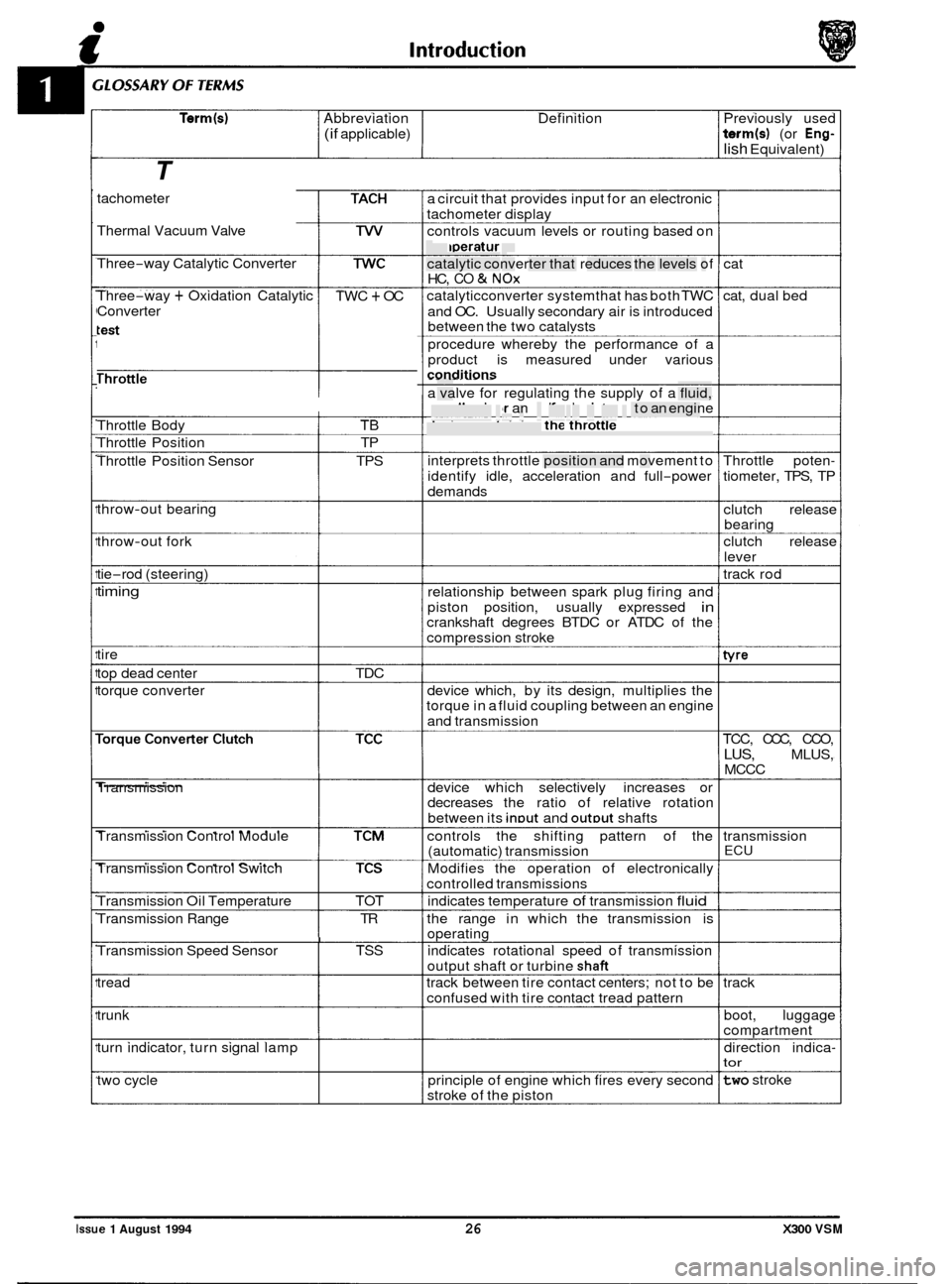
Term(s) Abbreviation Definition Previously used
(if applicable) term(s) (or Eng-
lish Equivalent)
T
tachometer
Thermal Vacuum Valve
Three
-way Catalytic Converter
Three
-way + Oxidation Catalytic
Converter TWC + OC
Throttle
------I
Throttle Body TB
Throttle Position TP
Throttle Position Sensor TPS
throw
-out bearing
throw
-out fork
tie
-rod (steering)
timing
tire
top dead center TDC
torque converter
Transmission
Transmission Control Module
Transmission Control Switch
Transmission Oil Temperature TOT
Transmission Range TR
I Transmission Speed Sensor TSS
tread
trunk
turn indicator, turn signal lamp
two cycle a
circuit that provides input for an electronic
tachometer display
controls vacuum levels or routing based on
temperature
catalytic converter that reduces the levels of
HC,
CO & NOx
catalyticconverter systemthat has both TWC
and OC. Usually secondary air is introduced
between the two catalvsts
procedure whereby the performance of a
product is measured under various
conditions - - . -. . . - . . -
a valve for regulating the supply of a fluid,
usually air or an aidfuel mixture, to an engine
device containing the throttle
interprets throttle position and movement to
identify idle, acceleration and full
-power
demands
relationship between spark plug firing and
piston position, usually expressed
in crankshaft degrees BTDC or ATDC of the
compression stroke
device which, by its design, multiplies the
torque in a fluid coupling between an engine
and transmission
device which selectively increases or
decreases the ratio of relative rotation
between its
inDut and outDut shafts
controls the shifting pattern of the
(automatic) transmission
Modifies the operation of electronically
controlled transmissions
indicates temperature
of transmission fluid
the range in which the transmission is
operating
indicates rotational speed of transmission
output shaft or turbine
shaft
track between tire contact centers; not to be
confused with tire contact tread pattern
principle of engine which fires every second
stroke of the piston cat
cat, dual bed
Throttle poten
-
tiometer, TPS, TP
clutch release
bearing
clutch release
lever
track rod
tvre
TCC, CCC, CCO,
LUS, MLUS,
MCCC
transmission
ECU
track boot, luggage
compartment
direction indica
- tor
two stroke
Issue 1 August 1994 26 X300 VSM
Page 144 of 521

Automatic Transmission (AJI 6)
8.1.3 TRANSMISSION CONTROL MODULE, RENEW
0 (4, OL)
SRO 44.15.32
. Raise the trunk lid and disconnect the battery.
. Remove the passenger side dash liner for access.
Displace and remove the air conditioning footwell outlet
duct.
. Release and remove the footwell carpet securing fastener:
displace and reposition the carpet for access.
Release the Transmission Control Module
(TCM) bracket
to body bracket securing nut
(1 Fig. 1).
. DisplacetheTCM mounting brackettang (2 Fig. 1)fromthe
body bracket and mounting stud.
= Reposition the TCM, release the TCM multi-pin plug lever
lock and disconnect the multi
-pin plug (3 Fig. 1).
. Release and remove the TCM mounting bracket securing
bolts and remove the TCM.
= Fit and align the new TCM to the mounting bracket.
. Fit and tighten the TCM securing bolts.
. Connect the TCM harness multi-pin plug and secure the
Position the TCM to body mounting bracket, ensuring that
Fit and tighten the TCM securing nut.
. Position the footwell carpet and fit the carpet fastener.
. Fit and align the footwell outlet duct to air conditioning
. Position and fit the duct fastener to the blower motor slot.
. Refit the dash liner.
. Reconnect the battery.
multi-pin plug lever lock.
the tang locates
in the bracket slot and stud.
unit.
1
i
J44-703 U
Fig. 1
Issue 1 August 1994 X300 VSM 7
Page 294 of 521
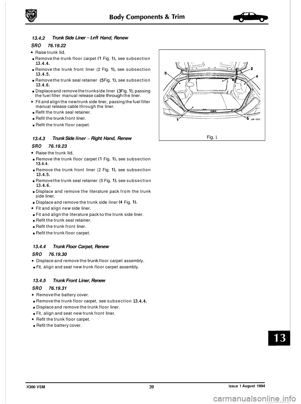
13.4.2
SRO 76.19.22
Raise trunk lid.
. Remove the trunk floor carpet (1 Fig. I), see subsection
13.4.4.
. Remove the trunk front liner (2 Fig. I), see subsection 13.4.5.
. Remove the trunk seal retainer (5 Fig. I), see subsection 13.4.6.
. Displace and remove the trunkside liner (3 Fig. I), passing
the fuel filler manual release cable through the liner.
9 Fit and align the new trunk side liner, passing the fuel filler
manual release cable through the liner.
. Refit the trunk seal retainer.
. Refit the trunk front liner.
. Refit the trunk floor carpet.
Trunk Side Liner - Left Hand, Renew
13.4.3 Trunk
Side liner
- Right Hand, Renew
SRO 76.19.23
Raise the trunk lid.
. Remove the trunk floor carpet (1 Fig. I), see subsection
. Remove the trunk front liner (2 Fig. I), see subsection
. Remove the trunk seal retainer (5 Fig. I), see subsection
. Displace and remove the literature pack from the trunk
. Displace and remove the trunk side liner (4 Fig. 1).
' Fit and align new side liner.
. Fit and align the literature pack to the trunk side liner.
. Refit the trunk seal retainer.
. Refit the trunk front liner.
. Refit the trunk floor carpet.
13.4.4.
13.4.5.
13.4.6.
side liner.
13.4.4 Trunk Floor Carpet, Renew
SRO 76.19.30
Displace and remove the trunk floor carpet assembly. 0
. Fit, align and seat new trunk floor carpet assembly.
13.4.5 Trunk Front Liner, Renew
SRO 76.19.31
Remove the battery cover.
. Remove the trunk floor carpet, see subsection 13.4.4.
. Displace and remove the trunk floor liner.
. Fit, align and seat new trunk front liner.
* Refit the trunk floor carpet.
. Refit the battery cover.
Fig. 1
Issue 1 August 1994 X300 VSM 39
Page 378 of 521
Electrical IT
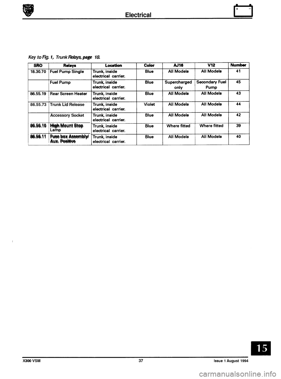
Key to Fig. 1, Trunk Relays, page 18.
, 86.55.73 Trunk Lid Release
Accessory
Socket
86.56.10 High Mount Stop
86.56.11 Fuse box Assembly/
! Aux. Positive
X300 VSM 37 Issue 1 August 1994
Page 477 of 521
page e
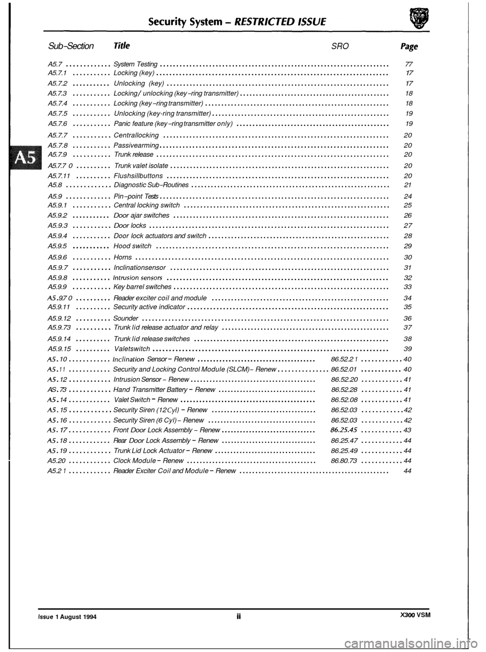
Sub-Section Title SRO
A5.7 ............. System Testing ...................................................................... 77
A5.7.1
........... Locking (key) ....................................................................... \
17
A5.7.2 ........... Unlocking (key) .................................................................... 17
A5.7.3 ........... Locking / unlocking (key-ring transmitter) ............................................... 18
A5.7.4
........... Locking (key-ring transmitter) ......................................................... 18
A5.7.5
........... Unlocking (key-ring transmitter) ....................................................... 19
A5.7.6
........... Panic feature (key-ring transmitter only) ................................................ 19
A5.7.7
........... Centrallocking ..................................................................... 20
A5.7.8
........... Passivearming ...................................................................... 20
A5.7.9
........... Trunk release ....................................................................... \
20
A5.7.7
0 .......... Trunk valet isolate ................................................................... 20
A5.7.11
.......... Flushsillbuttons .................................................................... 20
A5.9
............. Pin-point Tests ...................................................................... 24
A5.8
............. Diagnostic
Sub-Routines ............................................................. 21
A5.9.1
........... Central locking switch ............................................................... 25
A5.9.2
........... Door ajar switches .................................................................. 26
A5.9.3
........... Door locks ........................................................................\
. 27
A5.9.4
........... Door lock actuators and switch ........................................................ 28
A5.9.5
........... Hood switch ....................................................................... \
29 e
A5.9.6 ........... Horns ........................................................................\
..... 30
A5.9.7
........... Inclinationsensor ................................................................... 31
A5.9.8
........... Intrusionsensors .................................................................... 32
A5 . 9.7 0 .......... Reader exciter coil and module ....................................................... 34
A5.9.12
.......... Sounder ........................................................................\
... 36
A5.9.14
.......... Trunk lid release switches ............................................................ 38
A5.9.15
.......... Valetswitch ........................................................................\
39
A5 . 10 ............ Inclination Sensor - Renew ...................................... 86.52.2 1 ............ 40
A5 . 12 ............ Intrusion Sensor - Renew ........................................ 86.52.20 ............ 41
A5 . 14 ............ Valet Switch - Renew ........................................... 86.52.08 ............ 41
A5.9.9
........... Key
barrel switches .................................................................. 33
A5.9.11
.......... Security active indicator .............................................................. 35
A5.9.73
.......... Trunk lid release actuator and relay .................................................... 37
A5 . 11 ............ Security and Locking Control Module (SLCM) - Renew ............... 86.52.01 ............ 40
AS
. 73 ............ Hand Transmitter Battery - Renew ................................ 86.52.28 ............ 41
A5 . 15 ............ Security Siren (12 Cyl) - Renew .................................. 86.52.03 ............ 42
A5 . 16 ............ Security Siren (6 Cyl) - Renew ................................... 86.52.03 ............ 42
A5 . 17 ............ Front Door Lock Assembly - Renew ............................... 86.25.45 ............ 43
A5 . 18 ............ Rear Door Lock Assembly - Renew ............................... 86.25.47 ............ 44
Trunk Lid Lock Actuator - Renew ................................. 86.25.49 ............ 44
Clock Module - Renew ......................................... 86.80.73 ............ 44
Reader Exciter Coil and Module - Renew ............................................... 44
e
A5 . 19 ............
A5.20 ............
A5.2 1 ............
e
X300 VSM Issue 1 August 1994 ii
Page 478 of 521
0
c
doors, windows, trunk, hood and sliding roof.
I Method I UK / EUROPE
of IXJ16I1SOVIIDAIM
Operation Sport XJ12 /DD6
Locking
Central locking Key X X X
Remote central locking Remote X X X
Deadlocking Remote/ X X X
Two stage unlock Remote/
- - - Key
Key
Drive away locks Auto X/DD X/DD X/DD
Switch
close
Interior trunk lid release Switch
Flush
sill buttons /
intrusion override
security
Security system (base)
Intrusion sensing (full)
Inclination sensing
Passive arming
Panic alarm
Audible tones (error
/
deadlock)
Engine immobilization
*
Auto
.,,,
Remote
Auto
1 XI X X
X D
D D
X/ DD
X
-~~
Security System - RESTRICTED ISSUE
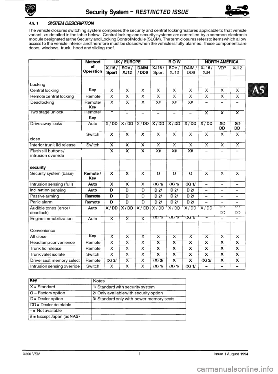
AS. 1 SYSTEM DESCRIPTION
The vehicle closures switching system comprises the security and central locking features applicable to that vehicle
variant, as detailed in the table below. Central locking and security systems are controlled by a common electronic
module designated as the Security and Locking Control Module (SLCM). The term closures refersto items which allow
access to the vehicle interior and therefore must be closed when the vehicle is fully alarmed. these components are
Convenience
All close Key X X X
Headlamp convenience Remote X X X
Trunk lid release Remote X X X
Trunk valet isolate Switch X X X
Driver seat memory select Remote
(X) 3/ X X
Intrusion sensing override Switch X X X
ROW NORTH AMERICA
XJ16/ SOV/ DAlM/ XJ16/ VDP XJ12
Sport XJ12 DD6 XJR
X X X X X X
I X X X X X X
X# X# X# - - -
$$$$$ DD DD
I I I I I X X X X X X
X X X X X X
X# X# X# - - -
I 0 0 0 X X X
X/DD X/DD X/DD X/DD
DD DD
(X) 1/ (XI 1/ (XI 1/ - - -
X X X X X X
Key Notes
X = Standard
0 = Factory option
D
= Dealer option
DD
= Dealer deletable
1/ Standard with security system
2/ Only available with security option
3/ Standard only with power memory seats
- = Not available
# = Except Japan (as NAS)
X300 VSM 1 Issue 1 August 1994
Page 480 of 521
I 03 I Door lock actuators (4 off) 1 part of door assemblv I I
Issue 1 August 1994 X300 VSM 3 I
1 04 I Door lock switches (2 off) I part of door latch assembly I I
1 05 IHoodswitch 1 located above siren I I
1 06 IHorn 1 located on front RH side of en(
1 07 I Inclination sensor I behind luggage compartment LH liner I I
I 08 I Intrusion sensor (LH) I located above LH door behind roof lining I
I 09 I intrusion sensor (RH) 1 located above LH door behind roof lining I
I
1 1 part of door latch assembly I 10 I Key barrel switches (2 off)
1 11 I Key fob transmitter 1 part of key fob I I
I 12 I Key transponder 1 part of key I I
I 13 I Reader exciter coil 1 part of ignition switch I I
I 14 I Reader exciter module 1 part of steering column assembly I I
1 15 I Relays (deadlock) I I I
1 18 I Security active indicator part of central locking switch I I
I 19 I Securitv and lockina control module (SLCM) located in luaaaae compartment behind LH liner I I
1 20 ISounder , located on front RH side of engine bay I I
1 25 IValet switch 1 in centre console compartment I I
A5.2 COMPONENT DESCR/PT/O NS I
stem - RESTRICTED ISSUE
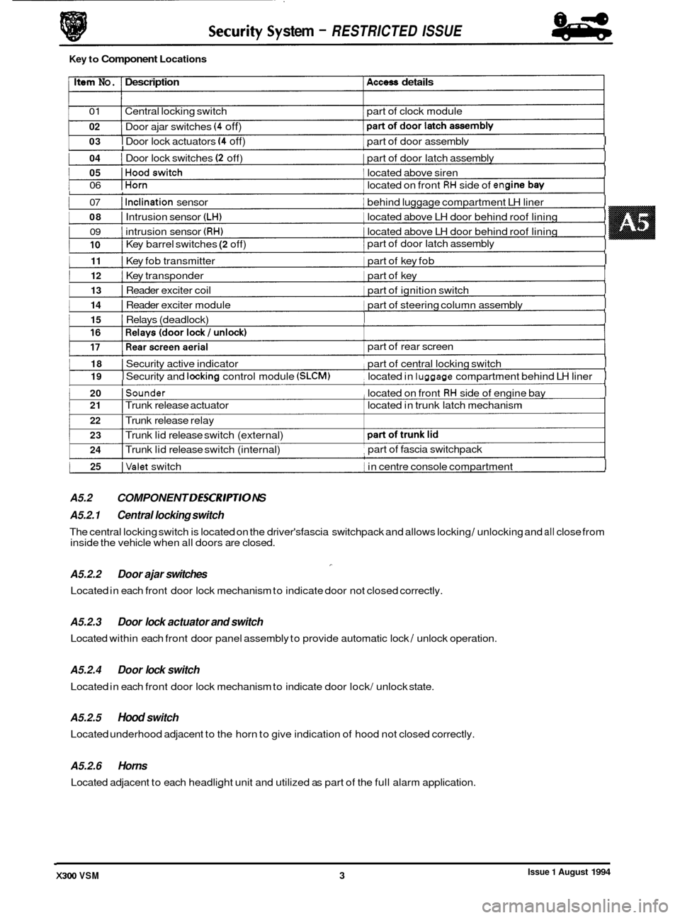
Key to Component Locations
Item No. Description Access details
01 Central locking switch part of clock module
02
1 I
Door ajar switches (4 off)
I I
part of rear screen
I 21 I Trunk release actuator located in trunk latch mechanism
22 I Trunk release relay
23
24 I Trunk lid release switch (external)
I Trunk lid release switch (internal) part of
fascia switchpack ,
A5.2.1 Central locking switch
A5.2.2 Door ajar switches
Located in each front door lock mechanism to indicate door not closed correctly.
-
The central locking switch is located on the driver'sfascia switchpack and allows locking / unlocking and all close from
inside the vehicle when all doors are closed.
A5.2.3
Located within each front door panel assembly to provide automatic lock / unlock operation.
Door lock actuator and switch
A5.2.4 Door lock switch
Located in each front door lock mechanism to indicate door lock/ unlock state.
A5.2.5 Hood switch
Located underhood adjacent to the horn to give indication of hood not closed correctly.
A5.2.6 Horns
Located adjacent to each headlight unit and utilized as part of the full alarm application.
Page 482 of 521
Security System
Pin No. Signal Description
01 0 / P Deadlock (front right / rear left)
02
0 / P Unlock driver's door
03
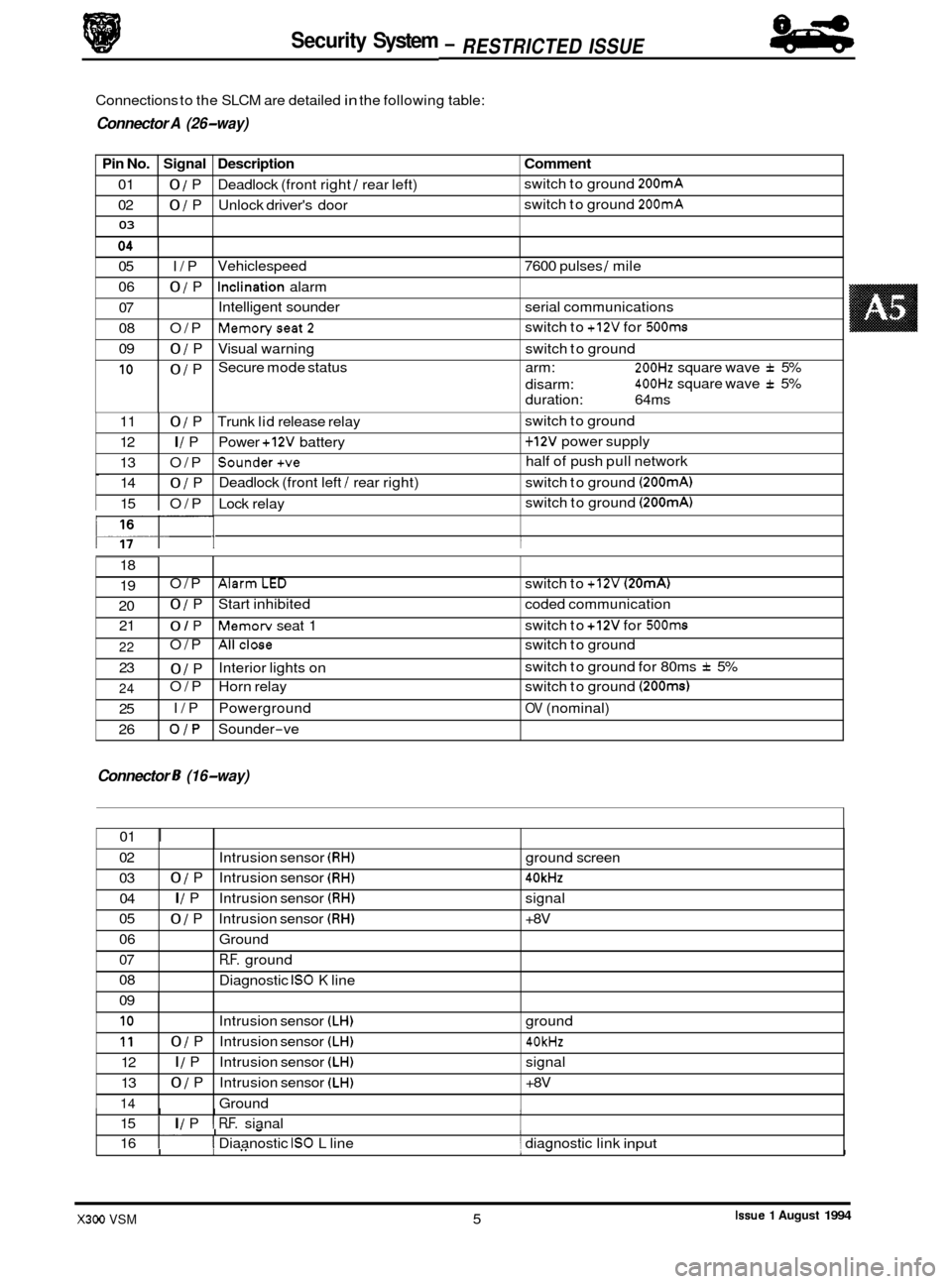
Connections to the SLCM are detailed in the following table:
9 Connector A (26-way)
Comment
switch to ground 200mA
switch to ground 200mA
05 I/P
06
0 / P
07
08 O/P
09
0 / P
10 0 / P Vehiclespeed
7600 pulses
/ mile
Inclination alarm
Intelligent sounder serial communications
Memoryseat2
Visual warning switch to ground
Secure mode status arm:
200Hz square wave f 5%
400Hz square wave f 5%
switch
to
+12V for 500ms
disarm:
duration: 64ms
0
117- I I
11 0 / P Trunk lid release relay 1 switch to ground
12
I / P Power +12V battery 1 + 12V power supply
13 O/P
Sounder+ve half of push pull network
14
0 / P Deadlock
(front left / rear right) switch to ground (200mA)
15 O/P Lock relay switch
to ground (200mA)
18
19
20 21 O/P
AlarmLED switch
to +12V (20mA)
0 / P Start inhibited coded communication
0 / P Memorv seat 1 switch
to +12V for 500ms
Connector 8 (16-way)
22
23
24
25
26 O/P
Allclose switch
to ground
0 / P
O/P Horn relay switch to ground
(200ms)
I/P Powerground OV (nominal)
OJP Sounder-ve
Interior lights
on switch
to ground for 80ms
f 5%
01
I
02
03 04
05
06
07
08
09
I I I I 15 I I / P I R.F. sianal
Intrusion
sensor
(RH) ground screen
0 / P Intrusion sensor (RH) 40kHz
I / P Intrusion sensor (RH) signal
0 / P Intrusion sensor (RH) +8V
Ground
R.F. ground
Diagnostic
IS0 K line
I. I - I 16 I I Diaanostic IS0 L line 1 diagnostic link input
10
11
12
13
14
.I
I I" 1- I
Intrusion sensor (LH) ground
0 / P Intrusion sensor (LH) 40kHz
I / P Intrusion sensor (LH) signal
0 / P Intrusion sensor (LH) +8V
Ground
Issue 1 August 1994 X300 VSM 5
84
- RESTRICTED ISSUE -
Page 484 of 521
lities.
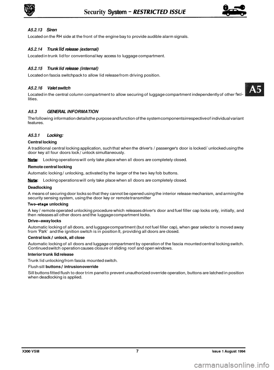
A5.3 GENERAL INFORMATION
The following information detailsthe purpose and function of the system components irrespective of individual variant
features.
A5.3.1 Locking:
Central locking
A traditional central locking application, such that when the driver's / passenger's door is locked / unlocked using the
door key all four doors lock / unlock simultaneously.
1ynfe: Locking operations will only take place when all doors are completely closed.
Remote central locking
Automatic locking / unlocking, activated by the larger of the two key fob buttons.
1ynfe: Locking operations will only take place when all doors are completely closed.
Deadlocking
A means of securing door locks so that they cannot be opened using the interior release mechanism, and arming the
security sensing system, using the door key or remote transmitter
Two-otage unlocking
A key / remote operated unlocking procedure which releases driver's door and fuel filler cap locks only, initially, and
then releases all other doors and the luggage compartment locks.
Drive-away locks
Automatic locking of all doors, and luggage compartment (but not fuel filler cap), when gear selector is moved away
from 'Park' and the ignition switch is in position II, providing all doors are closed.
Central lock / unlock, all close
Automatic locking of all doors and luggage compartment by operation of the fascia mounted central locking switch.
Continued switch operation causes closure of sliding roof and open windows.
Interior trunk lid release
Trunk lid unlocking from fascia mounted switch.
Flush sill buttons / intrusion override
Sill buttons fitted flush to door trim panel to prevent unauthorized override operation, buttons are latched in position
when deadlocking is applied.
Security System - RESTRKTED lSSUE
A5.2.13 Siren
Located on the RH side at the front of the engine bay to provide audible alarm signals.
A5.2.14 Trunk lid release (external)
Located in trunk lid for conventional key access to luggage compartment.
A5.2.15 Trunk lid release (internal)
Located on fascia switchpack to allow lid release from driving position.
A5.2.16 Valet switch
Located in the central column compartment to allow securing of luggage compartment independently of other faci-
X300 VSM 7 Issue 1 August 1994
Page 485 of 521
Security System - RESTRICTED ISSUE 8-8
-
A5.3.2 Security system
Base system
Provides standard vehicle arming, ie door ajar, actuator lockstatus, trunk lid or hood ajar and passenger door unlock- ing, does not include inclination or
Intrusion sensing
Detection of intrusion into the passenger compartment by removal or breakage of any glazed area, entry via any pro- tected enclosure and unauthorized door opening detection.
Inclination (tilt) sensing
Detection of unauthorized jacking /towing.
Passive arming
Arming of the security system, excluding intrusion sensors, without audible confirmation.
Audible tones
Audible indication of driver error when attempting to arm the system, or on initiation of deadlocking.
Engine immobilization
Automatic immobilization of the engine crank facility whenever the ignition key is turned to position 0.
A5.3.3 Convenience
All close
Automatic closure of open windows and sliding roof by prolonged action of key, or remote fob transmitter after door
locking.
Headlamp convenience
Automatic illumination of headlamps for driver convenience on operation of key fob button after locking sequence
completed.
Remote trunk lid release
Automatic release of the trunk lid lock on operation of the smaller key fob button after door unlocking.
Trunk valet isolate
Independent locking of the trunk lid to eliminate unauthorized entry to the luggage compartment.
Driver seat memory select
Automatic recall of a memorized driving position on operation of the smaller key fob button.
Intrusion sensing override
Allows intrusion sensing to be disabled until the next disarm action.
A5.3.4 Alarms
There are eight possible alarm activation modes; driver's door, hood, ignition key in (ignition auxiliary position, ignition ON), inclination, inner door handle action (causing actuator status switches to operate), intrusion, passenger door and
trunk.
Any of the above conditions occurring after the vehicle is fully armed will cause full alarm state.
Any of the above conditions, except door opening, occurring
after the vehicle is fully armed and active disarming is
selected will cause full alarm state. Door opening after active disarming selection will give a 30 second audible tick
period before full alarm is entered.
Any of the above conditions occurring
after the vehicle has been passively armed will give a 30 second audible tick
period before full alarm is entered.
Activation of full alarm state causes sidelights, direction indicators, interior lights or headlamps to flash (dependant
upon market variations), the security sounder to operate and the vehicle horns to operate
(if programmed to do so).
An error tone is generated if active arming is selected with either hood or trunk open, or the transmitter is pressed with
ignition key in auxiliary position.
0
X300 VSM Issue 1 August 1994 8